When you click on links to various merchants on this site and make a purchase, this can result in this site earning a commission. Affiliate programs and affiliations include, but are not limited to, the eBay Partner Network.
Does anyone know if the 20B OMP wiring is the same as Early FD?
The connectors looked the same and I wired it to my Haltech Elite 2500 the same way but it's giving me errors and not able to effectively move the position.
Originally I was trying to control the low side (2 middle B/W wires removed) but the OMP stayed closed and wouldn't move. When I switched the setting to control it both ways the OMP moved full open but now wont close and I'm wondering if I have the wiring incorrect to control the stepper, or I simply have a problem with the OMP.
Wiring diagrams/pinout are there, at least from the ECU perspective. You want page 2 of the wiring diagram for the position sensor. Look at ECU pins 3A for signal voltage, 3I for 5 volt reference of position sensor, and then a ground wire. For the OMP stepper look at page 6, and it's pin 4I, 4K, 4J, 4L for stepper poles with 2 ground wires.
See if that helps your troubleshooting. I think the short answer to your question is, it's functionally the same as other OMP's from that era. As to why your Haltech can't control it, I'm not sure. Maybe you have some wires crossed. But if it's possible to recreate the OEM control of the stock ECU, do it that way.
I followed the FD3S Diagram the best I could. I only had the wire colors on the OMP side to go from as I didn't have the original engine harness. Upon startup the position was reading accurately but it wouldn't move the motor. I changed the stepper settings in the Haltech and it moved the valve full open (96%) but still threw errors and wouldn't move it again. In the end I swapped 2 stepper wires and tried... no change. I swapped those wires back and swapped another 2 wires.... boom full function.
Either I made a mistake wiring up the OMP or the diagram wasn't the same, but it only took 2 attempts with the stepper outputs and after that it's working perfectly and moving very well. It was much easier in my build to swap the wires right at the ECU then to reach to the OMP as I have the connectors under the intake plenum and with Accufab clamps it's a little tight to remove!
could you please post your a wiring diagram of the working setup? I'm about to wiring my OMP and cant find my original harness so only have the OMP wire colors to work with.
My diagram is very complicated as it was a full harness build, based around my Haltech Elite 2500. I also had issues getting the OMP to function properly and I re-pinned it and can't remember if I updated my diagram after I got it sorted. Essentially the pump would go full open but not closed and it was as simple as re-pinning the ECU connector to switch Stepper 1 and 2 around or possibly 3 and 4.
On the 20B there was 2 connectors on the OMP and a short harness that also had 2 connectors. I modified the OEM Mazda stepper motor harness and put a 7 pin connector on it.
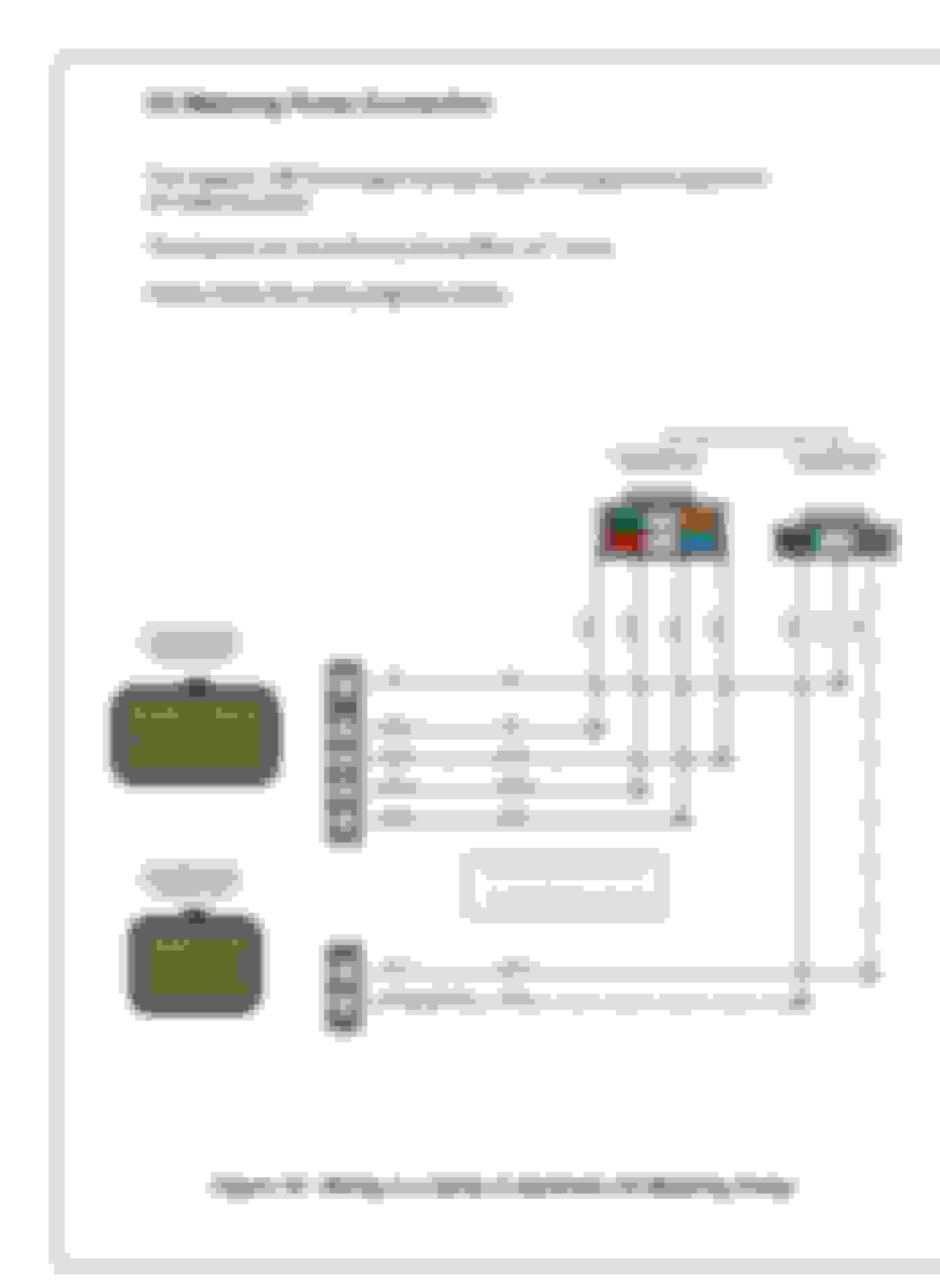
So you can better understand my drawing:
Pin 7 5V Supply Voltage
Pin 6 Stepper 1 Output
Pin 5 Stepper 2 Output
Pin 4 Stepper 3 Output
Pin 3 Stepper 4 Ouptut
Pin 2 OMP Feedback (pump position)
Pin 1 Sensor Ground
Thanks for the feedback and how you solved your problem. I just followed your steps of testing movement and switching wires - and happy to say I found the right combination! My OMP is working and NO DTC codes! finally...