Transistor trick for 2GCDFIS.

Burning Oil-Grinding 3rd
Joined: Apr 2002
Posts: 4,094
Likes: 1
From: Union Mills NC
http://www.electronicsworkbench.com/
We used this back when I was in school. It was not as good as spic at the time but cost much less.
We used this back when I was in school. It was not as good as spic at the time but cost much less.

Rotary Enthusiast
Joined: Oct 2001
Posts: 1,022
Likes: 4
From: Ontario, Canada
Originally Posted by gsl-se addict
Roger: Good point on the pulse width. I will see if we could control/limit it. The imporant thing is that the 2nd gen igniter uses the falling edge of the pulse to trigger (right?).Kent
Falling edge it is. I grabbed a couple pics during some testing tonight. Here's one.
Roger.
Thread Starter
Joined: Aug 2001
Posts: 15,725
Likes: 91
From: Near Seattle
Lots of good ideas are coming in. Thanks everyone.
Here is a MegaSquit circuit diagram that works fine to trigger the 2nd gen ignitor (it shows two out of the LED circuits, but we'd just need one of them).

Maybe we could build something like this and even have an LED monitor? Again, when the LED is on, the coil is not charging. It would be a conversation starter at least. "Hey, why is that blinking?" Actually it would only visibly blink at cranking and low idle speeds.
Thinking about it some more, if what Bill said is correct about the J-109, We could feed the C terminal 5 volts from a voltage reg (7805) and when its output grounds, it would trigger the transistor the same as the CPU in the MegaSquirt.
Or if that would short the voltage reg (sorry, it's late and I'm probably totally worng) maybe a 1k pull-up resistor between the C and B terminals would be better because it would still be ok to trigger the transistor with an appropriate resistor is series between the C terminal and transistor base. I could build one of these circuits with what I have laying around. A question remains about dwell and ignitor heating since I don't have access to a 2nd gen RX-7 to cop a feel when it's running. Luckily renns is on top of this issue. Thanks for taking the time to contribute to this discussion!
Here is a MegaSquit circuit diagram that works fine to trigger the 2nd gen ignitor (it shows two out of the LED circuits, but we'd just need one of them).
Maybe we could build something like this and even have an LED monitor? Again, when the LED is on, the coil is not charging. It would be a conversation starter at least. "Hey, why is that blinking?" Actually it would only visibly blink at cranking and low idle speeds.
Thinking about it some more, if what Bill said is correct about the J-109, We could feed the C terminal 5 volts from a voltage reg (7805) and when its output grounds, it would trigger the transistor the same as the CPU in the MegaSquirt.
Or if that would short the voltage reg (sorry, it's late and I'm probably totally worng) maybe a 1k pull-up resistor between the C and B terminals would be better because it would still be ok to trigger the transistor with an appropriate resistor is series between the C terminal and transistor base. I could build one of these circuits with what I have laying around. A question remains about dwell and ignitor heating since I don't have access to a 2nd gen RX-7 to cop a feel when it's running. Luckily renns is on top of this issue. Thanks for taking the time to contribute to this discussion!
Last edited by Jeff20B; Apr 7, 2005 at 05:48 AM.
Rotary Enthusiast
Joined: Oct 2001
Posts: 1,022
Likes: 4
From: Ontario, Canada
Here's a labelled pic of that trace posted earlier.
A: Coil -ve terminal floating at 12V, coil not charging
B: Coil -ve terminal pulled down to 0V, coil charging
C: Current limiting kicks in, holding coil charge until firing, but likely not adding any further coil energy.
D: Coil fires at the falling edge of trigger signal. The high spike is the flyback voltage, which when multiplied by the turn ratio of the coil determines the voltage needed to intially jump the plug gap.
Note that the coil starts charging _prior_ to receiving rising edge of trigger. This varies with trigger pulse width. Follow my earlier link for more details.
Roger.
Jeff: We could use a circuit like the one that I posted, but simplified. Since the J-109 acts as an open collector, it basically would take the place of the transition in the circuit. So, all we would need is two resistors (R2 and R3) and the zener. We could also use a 7805 regulator in place of the zener. The only thing is that our trigger signal would look different from what Roger posted. For us, the trigger signal would remain high (5v) until an ignition event was triggered. When the J-109 goes to fire, it pulls down the trigger voltage to ground thereby triggering the 2nd gen igniter. Basically the trigger trace would look like the inverse of what Roger posted.
There is a couple things that I worry about here. First: Would having the trigger level high for the majority of the time effect the operation of the 2nd gen igniter? Second: The J-109 is designed to see Vbatt on its output. With this design, it would see 5v. Without knowing what the internal circuity looks like in the J-109, I wonder if there might be some reverse flow of current, since the B terminal would still be at Vbatt. I think the use of a transistor (or two if needed) should be used t isolate the J-109 from the 2nd gen igniter. That way, the J-109 can use Vbatt and the 2nd gen could use 5v.
It would be really easy to add a LED. It would also be useful to make sure that the leading is working (although you could feel it from lack of power). I think that I would try to make a digital tach or something to measure ignition duty cycle or something just for fun.
Roger: Thanks for the posting traces. I think that will help in trying to figure out the requirements needed to make this work.
Kent
Thread Starter
Joined: Aug 2001
Posts: 15,725
Likes: 91
From: Near Seattle
Interesting. What if we hooked the J-109 to a PNP transistor to isolate it and then to the circuit diagram above? Use a 5 volt reg for VCC. The MS didn't send the ignitor into current limit mode because whenever the LED was off, it would charge the coil for a second or two and then automatically spark, relieving itself. A pretty smart design.
I made a short diagram of J-109 dwell duty % and RPM.
900-1000 RPM, 22% dwell
2000 RPM, 43% dwell
3000 RPM, 54% dwell
4000 RPM, 58% dwell
Any RPM above 4000 showed a decrease in dwell with a similar slope to the rising side observed at lower RPM.
I made a short diagram of J-109 dwell duty % and RPM.
900-1000 RPM, 22% dwell
2000 RPM, 43% dwell
3000 RPM, 54% dwell
4000 RPM, 58% dwell
Any RPM above 4000 showed a decrease in dwell with a similar slope to the rising side observed at lower RPM.
Okay, here is version 2 of the circuit:


This is at 8,000 engine rpms (266 Hz) with 60% duty. Is this what you meant, Jeff? I didn't know if you were talking engine rpm or dizzy rpm. I can easily run the simulation again if you want something different. You will see that the circuit is now non-inverting. I didn't add an LED yet as my PSPICE library does not seem to have any. I will probably have to put together a model for the LED, if we want one.
The output of the J-109 should be a resistor between the B and C terminals and then the C terminal connects to the resistor, R1. The B terminal would supply Vbatt and the C terminal would then pull it down. Probably a 1k or so resistor would work well for that.
This circuit would probably work. The currents all look reasonable. I reduced R2 to 330 ohms to make sure we have enough current available to trigger the igniter. The max current would be (Vbatt-Vzener)/R2 = (13.5-4.7 (or 5.1))/330 = about 26 mA. The zener sees about 20 mA, but spikes to as high as 40 mA when the circuit switches (the zener is rated for 400 mA, so this is no problem).
Let me know what you guys think. If we get together what we think is a good circuit, maybe Jeff and I (and anyone else) could be test subjects. I don't have direct fire yet, but I could pick-up a 2nd gen coil and see how it works.
Kent
Thread Starter
Joined: Aug 2001
Posts: 15,725
Likes: 91
From: Near Seattle
8k and 60%? Good enough. I was talking about engine RPM (so we want two ignition events per revolution). Either way is fine as long as nobody gets confused.
Yep, adding a resistor between B and C is standard practice when an ignitor is used wothuout a coil. The MegaSquirt people recommend 1k. I've had minimal heating using a 1/4 watt, but a 1/2 watt is fine if you have the room.
Here is an example that I've had good results with bench testing and then tonight in a succesful first time cranking effort on my engine; a steady 100 RPM was seen in the tuning software with resistors placed appropriately in the circuit according to this diagram.

Regarding your circuit, I believe the 2nd gen ignitor has circuit protection on the trigger wire. It's best to be safe, but I haven't burned mine out yet (knock on wood). I've tried triggering it from a 1st gen dizzy and also a 2nd gen CAS. The VR sensors in those go from 0V to fairly high voltage at high RPM. I don't know quite how high the voltage actually gets, but being an inductor, it will have some degree of self-cancelation as the RPM increases (which doesn't really help us here). Anyway, if I remember right, it was able to condition the 12-1 signal from my modded CAS when it was in my drill press at mid to high RPM, but couldn't do its job at lower RPM because the incoming voltage was below its trigger threshold, or something. Now that I think about it, I wish I would have measured the voltage from the VR sensor at the point the ignitor stopped conditioning. I bet it was below 5 volts.
So to answer your concern, the spike you mentioned may not be a problem.
I need to say that I still don't understand discreet electronics, such as these, very well. I'd like to build a test circuit to try the transistor trick out, and will very likely use the MegaSquirt LED circuit diagram because I have some experience with it, and it worked for me. I wish I could something useful to your PSPICE schematic, but even the Megasquirt schematic makes me feel dumb sometimes.
I started another diagram with a 7805 regulator, but it wasn't flowing (mentaly speaking) so I set it aside. I'll get back to it tonight or tomorrow morning.
I was talking about engine RPM (so we want two ignition events per revolution). Either way is fine as long as nobody gets confused.Yep, adding a resistor between B and C is standard practice when an ignitor is used wothuout a coil. The MegaSquirt people recommend 1k. I've had minimal heating using a 1/4 watt, but a 1/2 watt is fine if you have the room.
Here is an example that I've had good results with bench testing and then tonight in a succesful first time cranking effort on my engine; a steady 100 RPM was seen in the tuning software with resistors placed appropriately in the circuit according to this diagram.
Regarding your circuit, I believe the 2nd gen ignitor has circuit protection on the trigger wire. It's best to be safe, but I haven't burned mine out yet (knock on wood). I've tried triggering it from a 1st gen dizzy and also a 2nd gen CAS. The VR sensors in those go from 0V to fairly high voltage at high RPM. I don't know quite how high the voltage actually gets, but being an inductor, it will have some degree of self-cancelation as the RPM increases (which doesn't really help us here). Anyway, if I remember right, it was able to condition the 12-1 signal from my modded CAS when it was in my drill press at mid to high RPM, but couldn't do its job at lower RPM because the incoming voltage was below its trigger threshold, or something. Now that I think about it, I wish I would have measured the voltage from the VR sensor at the point the ignitor stopped conditioning. I bet it was below 5 volts.
So to answer your concern, the spike you mentioned may not be a problem.
I need to say that I still don't understand discreet electronics, such as these, very well. I'd like to build a test circuit to try the transistor trick out, and will very likely use the MegaSquirt LED circuit diagram because I have some experience with it, and it worked for me. I wish I could something useful to your PSPICE schematic, but even the Megasquirt schematic makes me feel dumb sometimes.
I started another diagram with a 7805 regulator, but it wasn't flowing (mentaly speaking) so I set it aside. I'll get back to it tonight or tomorrow morning.
Jeff: Yes, that is 8000 engine rpm that I ran (8000/60)*2 events per rotation = 266.66 Hz. This should be a limiting case as the actual circuit probably would never see that combination, but I will go ahead and run 4000 engine rpm too.
We have a couple options: First we could use a circuit like the second one I posted. It is non-inverting and only uses one transistor. The only limitation is that it could only provide a maximum of 26 mA to the igniter. So if the igniter requires more (I don't think it would), this circuit may not be the best bet. The other option is to do something similar to what you posted in your last diagram. We could use two inverting stages to get a non-inverting output. That way it would be easy to incorporate the LED and the circuit could handle up to whatever the 7805 can provide (1 amp, I think), but would require a pair of transistors. I will go ahead and model both circuits up and see how they behave. I don't think I have a model for the 7805, so I will just assume it to be a 5v voltage source.
We have a couple options: First we could use a circuit like the second one I posted. It is non-inverting and only uses one transistor. The only limitation is that it could only provide a maximum of 26 mA to the igniter. So if the igniter requires more (I don't think it would), this circuit may not be the best bet. The other option is to do something similar to what you posted in your last diagram. We could use two inverting stages to get a non-inverting output. That way it would be easy to incorporate the LED and the circuit could handle up to whatever the 7805 can provide (1 amp, I think), but would require a pair of transistors. I will go ahead and model both circuits up and see how they behave. I don't think I have a model for the 7805, so I will just assume it to be a 5v voltage source.
Thread Starter
Joined: Aug 2001
Posts: 15,725
Likes: 91
From: Near Seattle
Yeah, the 7805 boasts up to 1.0 amps on the back of the package. The 7805 doesn't really need any special treatment in your circuit model. It's just a 5v source. It's nice to add it for completeness though.
I called it the 'mystery box' above because I wasn't sure what type of circuit would go inside. Here's one that I think will work.
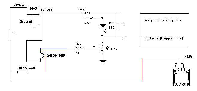
I think a 390 ohm will be enough to bring 12v down to 5v for the transistor, but I'm not sure. Again I'm not good with discreet electronics, but I think it will work. Just to be sure, let me see if I understand what's supposed to be hapening here. When the J-109 is NOT recieving a signal from the VR sensors in the dizzy, it is not triggering the coil, or in our case, the transistor. The PNP in the isolation circuit should be on, as well as the PNP and the LED in the trigger circuit. As soon as the J-109 recievs a trigger signal and goes low, it will ground the PNP and cut the isolation circuit. This will in turn cut the trigger ciruit turning off the LED and sending 5v to the 2nd gen ignitor.
Let me know if I screwed up anywhere.
I called it the 'mystery box' above because I wasn't sure what type of circuit would go inside. Here's one that I think will work.
I think a 390 ohm will be enough to bring 12v down to 5v for the transistor, but I'm not sure. Again I'm not good with discreet electronics, but I think it will work. Just to be sure, let me see if I understand what's supposed to be hapening here. When the J-109 is NOT recieving a signal from the VR sensors in the dizzy, it is not triggering the coil, or in our case, the transistor. The PNP in the isolation circuit should be on, as well as the PNP and the LED in the trigger circuit. As soon as the J-109 recievs a trigger signal and goes low, it will ground the PNP and cut the isolation circuit. This will in turn cut the trigger ciruit turning off the LED and sending 5v to the 2nd gen ignitor.
Let me know if I screwed up anywhere.
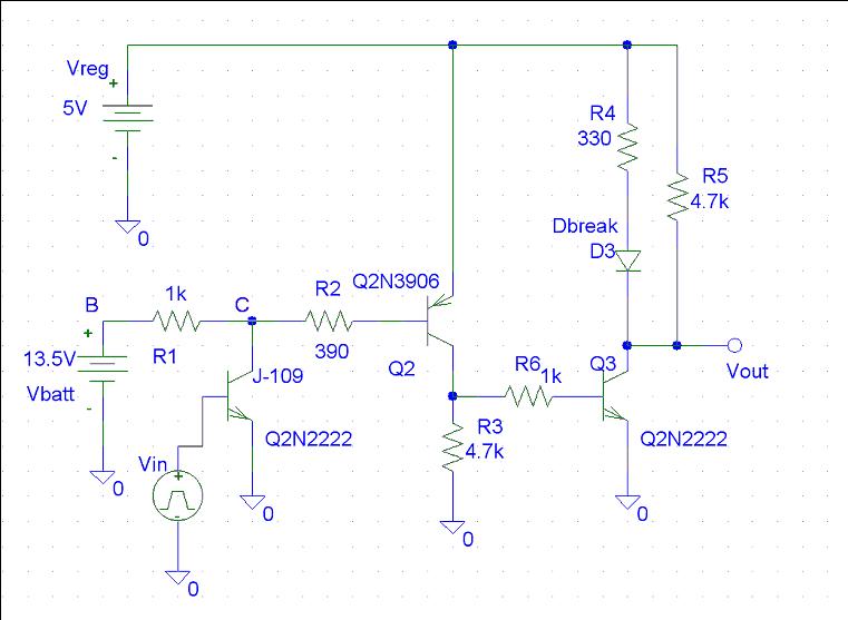
Jeff, here is a model of the updated circuit:

The simulation is at 4000 engine rpm with 60% duty (J-109 firing 60% of the time). The Dbreak in the circuit is the LED (modeled a typical red LED).

The simulation is at 4000 engine rpm with 60% duty (J-109 firing 60% of the time). The Dbreak in the circuit is the LED (modeled a typical red LED).
Thread Starter
Joined: Aug 2001
Posts: 15,725
Likes: 91
From: Near Seattle
Those both look great! I see you added an NPN transistor to the isolation circuit. I think I understand everything about the rest of the schematic, but I'm a little confused with the isolation circuit. The B and C connections are there... What is Vin? Is that part of the circuit PSPICE's representation of a J-109?
Next question. Is a 390 ohm resistor the correct choice here to resist up to 13.8 or 14 volts? I chose it because that's what's on the RPM input circuit of the MegaSquirt. It's a half watt that is soldered above the circuit board for better heat disipation. During running, it won't heat up, but when sitting in an 'on' state, it will be fed continuous battery voltage with enough current to keep a couple transistors on. I guess what I'm asking is this: Is PSPICE happy with the our latest circuit? Or better yet, what type of current are we talking about?
Next question. Is a 390 ohm resistor the correct choice here to resist up to 13.8 or 14 volts? I chose it because that's what's on the RPM input circuit of the MegaSquirt. It's a half watt that is soldered above the circuit board for better heat disipation. During running, it won't heat up, but when sitting in an 'on' state, it will be fed continuous battery voltage with enough current to keep a couple transistors on. I guess what I'm asking is this: Is PSPICE happy with the our latest circuit? Or better yet, what type of current are we talking about?
I just used that extra NPN to represent the J-109 igniter. The igniter acts as an open collector as Bill mentioned before. The B and C are the terminals of the J-109 (one sees Vbatt and the other acts as a collector (pulls down the (-) terminal on the coil normally). Vin is just a square wave for the simulation. Basically just like the signal from the VR cleaned up and put into a simple square wave. The Vin with the NPN were used to simulate VR sensor and the J-109 together. I think this will be fine for simulation purposes.
I will have to double check the currents, but from what I remember, this circuit used much less current than the previous designs. This is mainly because the previous designs had current flowing through the zener at all times (sometimes less than others). I think the 390 will be fine.
I will go check the currents and power dissipation. I will check it will check it in both the firing state an non-firing state. That should give us the full range of what we could expect the circuit to see. Actual operation will be somewhere in between.
Kent
Thread Starter
Joined: Aug 2001
Posts: 15,725
Likes: 91
From: Near Seattle
Ah, now your schematic makes sense to me. That'd be great if you could measure currents in both states.
I can mess with this circuit now that I've got some time. Is anyone else going to try to build it?
I can mess with this circuit now that I've got some time. Is anyone else going to try to build it?
Here are the operating conditions for the circuit.
Off state (not firing)

On state (firing)

Disregard the 400mA+ at Vin. This is because I forced the base to be at 5v. I reality the base should be at emitter voltage (ground in this case) + 0.6 or 0.7v. This is all internal to the igniter, so we don't need to worry about that part. The current draw in the off state is almost 0.
Ptotal (off) = 13.5v*19.98pA + 5v*67.22pA = 6.06E-10 W
Ptotal (on) = 13.5v*13.46mA + 5v*32.28mA = 3.43E-01 W
The 390 ohm resistor will dissipate about 41 mW max. It looks like 1/4 W resistor should be more than adequate everywhere in this circuit, but your are more than welcome to use 1/2 W to play it safe. I would be willing to test as well. I believe that I have all of the components except for the 7805. I will also need to track down a 2nd gen leading coil. If anyone else would like to test, but are unsure of their electorics abilities, I could put a circuit together for you and then you can install and test.
Kent
Off state (not firing)
On state (firing)
Disregard the 400mA+ at Vin. This is because I forced the base to be at 5v. I reality the base should be at emitter voltage (ground in this case) + 0.6 or 0.7v. This is all internal to the igniter, so we don't need to worry about that part. The current draw in the off state is almost 0.
Ptotal (off) = 13.5v*19.98pA + 5v*67.22pA = 6.06E-10 W
Ptotal (on) = 13.5v*13.46mA + 5v*32.28mA = 3.43E-01 W
The 390 ohm resistor will dissipate about 41 mW max. It looks like 1/4 W resistor should be more than adequate everywhere in this circuit, but your are more than welcome to use 1/2 W to play it safe. I would be willing to test as well. I believe that I have all of the components except for the 7805. I will also need to track down a 2nd gen leading coil. If anyone else would like to test, but are unsure of their electorics abilities, I could put a circuit together for you and then you can install and test.
Kent
Thread Starter
Joined: Aug 2001
Posts: 15,725
Likes: 91
From: Near Seattle
I have plenty of PN2222As, 1/4 watt 1k resistors and 1/2 watt 390 ohm resistors. I'll have to unsolder a 2N3906 from a circuit board here.
It looks like everything is within component limits. By the way, did you list the 10-15mA the LED will be using at 5v with a 330 ohm resistor? Or was it factored into the adjacent circuit?
It looks like everything is within component limits. By the way, did you list the 10-15mA the LED will be using at 5v with a 330 ohm resistor? Or was it factored into the adjacent circuit?
Rotary Enthusiast
Joined: Jun 2002
Posts: 1,058
Likes: 0
From: Yokosuka
Great work so far, guys. I had a question for you, though.
In your testing, Jeff, are you using stock 1st gen plugs? Do you think there would be any difference or benefit in using the 2nd gen's plugs as well in conjunction with these coils?
In your testing, Jeff, are you using stock 1st gen plugs? Do you think there would be any difference or benefit in using the 2nd gen's plugs as well in conjunction with these coils?
Thread Starter
Joined: Aug 2001
Posts: 15,725
Likes: 91
From: Near Seattle
Most definitely use 2nd gen BUR7EQ plugs with a 2nd gen coil. They're a 'surface discharge' type of plug and is best with a direct fire ignition system to fire them reliably as they require higher voltage than the 1st gen BR8EQ-14 do.
A simple rule of thumb to follow is to always match your plugs to your ignition system.
A simple rule of thumb to follow is to always match your plugs to your ignition system.
Originally Posted by Jeff20B
I have plenty of PN2222As, 1/4 watt 1k resistors and 1/2 watt 390 ohm resistors. I'll have to unsolder a 2N3906 from a circuit board here.
It looks like everything is within component limits. By the way, did you list the 10-15mA the LED will be using at 5v with a 330 ohm resistor? Or was it factored into the adjacent circuit?
It looks like everything is within component limits. By the way, did you list the 10-15mA the LED will be using at 5v with a 330 ohm resistor? Or was it factored into the adjacent circuit?
jayroc: I believe that Jeff believes in using plugs that match the ignition system. I think he uses 2nd gen plugs in the leading for his direct fire projects. I will likely get some 2nd gen plugs for the leading when I test the circuit.
I've been playing with this circuit a bit, and there seems to be some problem with the PNP transistor. The simulation shows that it should work fine, but I have tried multiple PNP transistors (2n3906 and others) and still have the same problem. With the way it is wired, if the point where the J-109 connects goes low or stays high, the LED comes on (output low). If I let the input float, then the LED will go out. From most of the circuits that I have seen that use PNP's, the emitter is usually connected to V+ and the current flows out through the collector. In this situation, the transition turns on when the signal goes low instead of when it goes high as in the case of the NPN transistor type. I will try tonight to use and NPN transistor in the place of the PNP and see what I can come up with.
Jeff: I was wondering if you had tried the circuit yet. If so, are you having the same problems?
Kent
Jeff: I was wondering if you had tried the circuit yet. If so, are you having the same problems?
Kent
This circuit may work better. The current draw is nearly the same as the last design, but maybe this will be a more reliable design. I will try to build the circuit a little later and will let you now how it works tomorrow. I changed R3 and R5 to 4.7k to reduce power consumption a bit. You can use 1k in their place, but the 4.7k cuts about 50 mW of power consumption (probably not enough to really matter). The 1k resistors would probably result in a bit better performance (faster switching).