
My Oil Cooler Swap

Ok, well instead of making a post saying, "oh look what I got today" and another saying "oh I got this", etc, I just decided to make one that I could add on to as I progress  .
.
So today I recieved the 2nd to last part I was waiting on. I got the oil PSI/temp block from Steve at www.rotaryautosports.com. It looks damn good. It comes with the block itself (anodized black, very cool), plugs for un-used outlets, pre assembled with teflon tape, 4 new O rings, two locking nuts, and the two lengthened studs for $38 plus shipping on his website. Anyway, the only complaint I have about it, is that the new studs that it came with are bigger around than what my oil filter neck uses, so I have to drill out the neck and tap it for the larger studs. Anyway, other than that, its a great product and I would recomend anyone to order from him. After all, its $10 cheaper than RB .
.
Now, for a question. I think I have this worked out, but Im not sure. On the oil filter neck where the two O rings go, there are two "indents" to seat the O rings in. There are two "indents" on the oil block also, but only on one side. First thought was that the O rings should be placed in the "indent" on the oi filter neck and then lined up with the "indents" on the block. Now, in a way that makes sense, but it seems to me that with both "indents" around the same O ring, there would be too much room and the O ring wouldnt seal well. Now my second thought was that I put the O rings in the "indents" on the filter neck, and then use the other side of the block without indents which would make a good seal, and also leaves "indents" on the bottom of the block to seat the O rings in against the engine. So, which way is this intended to be set up? Which way would you do?
Anyway, thats all for now. I will post later when I make some "real" progress with the swap. Hopefully this weekend.
~T.J.
.So today I recieved the 2nd to last part I was waiting on. I got the oil PSI/temp block from Steve at www.rotaryautosports.com. It looks damn good. It comes with the block itself (anodized black, very cool), plugs for un-used outlets, pre assembled with teflon tape, 4 new O rings, two locking nuts, and the two lengthened studs for $38 plus shipping on his website. Anyway, the only complaint I have about it, is that the new studs that it came with are bigger around than what my oil filter neck uses, so I have to drill out the neck and tap it for the larger studs. Anyway, other than that, its a great product and I would recomend anyone to order from him. After all, its $10 cheaper than RB
.Now, for a question. I think I have this worked out, but Im not sure. On the oil filter neck where the two O rings go, there are two "indents" to seat the O rings in. There are two "indents" on the oil block also, but only on one side. First thought was that the O rings should be placed in the "indent" on the oi filter neck and then lined up with the "indents" on the block. Now, in a way that makes sense, but it seems to me that with both "indents" around the same O ring, there would be too much room and the O ring wouldnt seal well. Now my second thought was that I put the O rings in the "indents" on the filter neck, and then use the other side of the block without indents which would make a good seal, and also leaves "indents" on the bottom of the block to seat the O rings in against the engine. So, which way is this intended to be set up? Which way would you do?
Anyway, thats all for now. I will post later when I make some "real" progress with the swap. Hopefully this weekend
.~T.J.
Ok, here are some pictures too, I almost forgot them, lol.
Oil block in all its greatness (showing "indents"):

The oil blocks other side (no "indents"):

The oil filter neck (showing "indents"):

The longer studs with nuts and O rings:

Sitting together...Kinda (does this look right?):

The stud problem (the reason I have to drill and tap):

The -AN fittings, adapters, and new crush washers:

So there you have it, all my oil cooler stuff in all its greatness.
~T.J.
Oil block in all its greatness (showing "indents"):
The oil blocks other side (no "indents"):
The oil filter neck (showing "indents"):
The longer studs with nuts and O rings:
Sitting together...Kinda (does this look right?):
The stud problem (the reason I have to drill and tap):
The -AN fittings, adapters, and new crush washers:
So there you have it, all my oil cooler stuff in all its greatness
.~T.J.
Ok, I think I have mine sitting right in the picture because I remembered DirectFreaks in his picture. I went back and looked, and sure enough, theyre sitting the same way. I realize that theyre two differnt oi filter necks, but I was looking at the oil block under the neck...
DirectFreaks setup:

The way I think mine goes:
If you notice, both blocks would be facing the same direction if mine was bolted to the car. I think I have it figured out now .
~T.J.
EDIT: I assembled it both ways I was talking about earlier. With the two "indents" aligned, I blew through the setup, and had a small leak around the O ring like I suspected. I thought maybe this was because I wasnt holding the neck and the block together tight enough, but then I flipped it over and tried it the way in the picture, and there were NO leaks and I didnt even have to hold the pieces together as tight. Anyway, just letting ya know I think I figured it out.
DirectFreaks setup:
The way I think mine goes:
If you notice, both blocks would be facing the same direction if mine was bolted to the car
. I think I have it figured out now .~T.J.
EDIT: I assembled it both ways I was talking about earlier. With the two "indents" aligned, I blew through the setup, and had a small leak around the O ring like I suspected. I thought maybe this was because I wasnt holding the neck and the block together tight enough, but then I flipped it over and tried it the way in the picture, and there were NO leaks and I didnt even have to hold the pieces together as tight. Anyway, just letting ya know I think I figured it out
.
Last edited by RotorMotorDriver; Jan 18, 2003 at 04:02 AM.
I read your email
Joined: Jan 2002
Posts: 2,624
Likes: 1
From: NW New Jersey
I wouldn't drill and tap if I were you. To me it doesn't look like there's enough "meat" on that pedistal for that larger stud plus you run the risk of destroying the part. I'd try get a longer stud in the same thread pitch as your original. When it's all bolted together it won't go anywhere. Looks good!
Airflow is my life
Joined: Aug 2002
Posts: 6,736
Likes: 2
From: Orlando, Fl
Your second steup is right. Think about the stock setup. Flat (no indents) on the egnine block. Grooves in the pedestal. So your just replicating it twice. Flat on the engine block, grooved side down on the adapter with the orings in them, flat side of the adapter up, pedestal with grooves and orings in it pressing down on the adapters flat surface.
Call Steve and see if he can send you the correct studs. I dont think those studs will go thruough the holes in the engine. They look way too big. Hell you got time to get it right.
Call Steve and see if he can send you the correct studs. I dont think those studs will go thruough the holes in the engine. They look way too big. Hell you got time to get it right.
I wouldn't drill and tap if I were you. To me it doesn't look like there's enough "meat" on that pedistal for that larger stud plus you run the risk of destroying the part.
~T.J.
EDIT: Here are some pictures I took to try and show scale and how much "meat" is actually there. Any comments?


Last edited by RotorMotorDriver; Jan 18, 2003 at 07:51 AM.
Trending Topics
Rotary Freak
Joined: Feb 2001
Posts: 2,524
Likes: 0
From: MN
I think you will find that your rear plate on the engine is already tapped for those M8 screws that he sent along with your sandwich plate. If this is the case you have to find longer studs in the smaller size. The kit that you bought looks to be for a different style filter head (maybe for a different year or something). But you can make it work by just simply getting new studs the same length as the M8's but in the smaller size (M6?).
Last edited by setzep; Jan 18, 2003 at 10:08 AM.
#!/sup_mod/�b3rg33k
Joined: Sep 2001
Posts: 96
Likes: 0
From: Kansas City
Originally posted by 82streetracer
on those AN fittings. how does the SS hose attach to the fitting?
how do you clamp it down.
on those AN fittings. how does the SS hose attach to the fitting?
how do you clamp it down.
-Error
The red part screws off, you slide the hose over the blue nipple, then screw the red part back on and it tightens around the hose. If that makes any sense.
-Error
-Error
.The red and blue pieces seperate:
Then, you slide the red piece over the hose:
Not Shown
Next, you put the nipple of the blue piece into the hose:
Last, you screw the red piece onto the blue piece while the blue nipple is in the hose. There is a "ridge" inside the red piece so that when the two pieces screw together it "crushes" the hose tight up against the blue nipple on the inside, and seals it:
Thats not EXACTLY how it works, but thats the way it seals anyway. There are a few things you have to watch when you put them together (read the assembly manual), but its a fairly simple process.
~T.J.
Originally posted by Rx7carl
So thats how earls does it. Different from aeroquip. Aero, you screw the red part onto the hose (it has threads inside), then the blue piece screws into the red part.
So thats how earls does it. Different from aeroquip. Aero, you screw the red part onto the hose (it has threads inside), then the blue piece screws into the red part.
. The only threads inside the red piece are for screwing the red and blue ones together. They didnt send my any instructions on how to do it, so this is just what I came up with combined from what Ive read in the Aeroquip manual.~T.J.
EDIT: I dont know how well you can see these pictures (I made them smaller to dl faster like the rest), but here you can see that the end of the red piece that slides over the hose is actually tapered to help you get the hose in, and when looking down the other end, there are only some barbs in the middle to grab the hose, and then the only threads in there are the ones that join the red piece to the blue piece.
Tapered end:
Threaded end:
Last edited by RotorMotorDriver; Jan 18, 2003 at 11:21 AM.
Airflow is my life
Joined: Aug 2002
Posts: 6,736
Likes: 2
From: Orlando, Fl
TJ, is swivel seal the style you have?
Look here for instructions.
http://www.holley.com/HiOctn/ProdLin...TS/Swivel.html
Or the general tech
http://www.holley.com/HiOctn/ProdLin...PTS/EPPTS.html
Look here for instructions.
http://www.holley.com/HiOctn/ProdLin...TS/Swivel.html
Or the general tech
http://www.holley.com/HiOctn/ProdLin...PTS/EPPTS.html
Haha, thanks Carl. I just found that site as well . Yes I have the swivel seal hose ends and the perform-o-flex hose. Good guess .
~T.J.
EDIT: Anyone catch this in step 6...

. Yes I have the swivel seal hose ends and the perform-o-flex hose. Good guess .~T.J.
EDIT: Anyone catch this in step 6...
If the hose has backed more than about 1/16" out of the socket as you assembled it, curse and return to Step 3.
Ok...Raise your hand if you want to throw your oil cooler across the street into your damn neighbors yard!?!?!?
I knew that with the fittings where they are was going to be a tight fit to get lines on them. I even cut the radiator side shroud to give more room. I tried all kinds of things. All futile attempts. I dont see this happening. The lines arent as flexable as I had hoped, so my plan was blown all to hell and back. I came up with another idea stading there, but it doesnt seem to work either...I dont know how Im gonna mount the damn cooler and still use the fittings that I already bought...**** . On a good note I have the adapters in the cooler with the new crush washers .
~T.J.
PS - Carl, I got your package today, thanks.
I knew that with the fittings where they are was going to be a tight fit to get lines on them. I even cut the radiator side shroud to give more room. I tried all kinds of things. All futile attempts. I dont see this happening. The lines arent as flexable as I had hoped, so my plan was blown all to hell and back. I came up with another idea stading there, but it doesnt seem to work either...I dont know how Im gonna mount the damn cooler and still use the fittings that I already bought...****
. On a good note I have the adapters in the cooler with the new crush washers .~T.J.
PS - Carl, I got your package today, thanks
.
Last edited by RotorMotorDriver; Jan 18, 2003 at 05:39 PM.
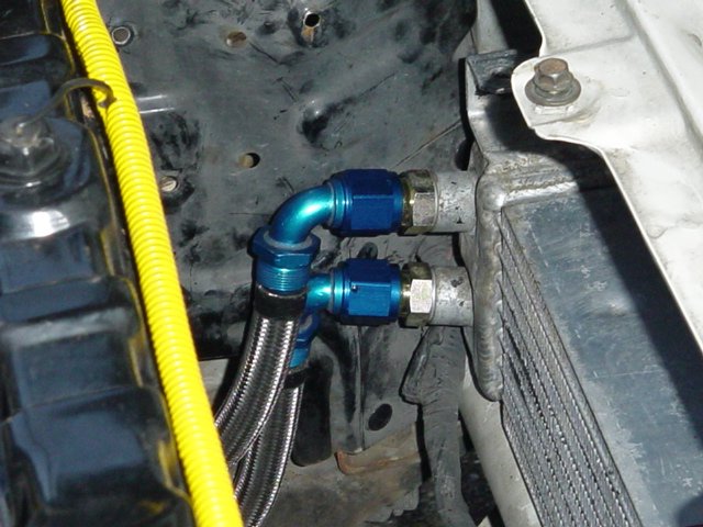
Ok, so maybe all hope isnt lost. After some creative thinking and careful moving of parts, I think I have a solution .
~T.J.
.~T.J.
Last edited by RotorMotorDriver; Jan 18, 2003 at 06:44 PM.
Airflow is my life
Joined: Aug 2002
Posts: 6,736
Likes: 2
From: Orlando, Fl
Cool, you got it???? ALRIGHT!!!! WTG USPS!!! No problem TJ, glad to help.
OIC, you were too close to the rad? Looks good from here so far. I think youll get it. Press on!!!!! Almost looks like my 2nd gen cooler installation. I tried to send u pics but your crappy email said my zip file was too big.
OIC, you were too close to the rad? Looks good from here so far. I think youll get it.
Press on!!!!! Almost looks like my 2nd gen cooler installation. I tried to send u pics but your crappy email said my zip file was too big.
Cool, you got it???? ALRIGHT!!!! WTG USPS!!! No problem TJ, glad to help.
. They look like theyre gonna work great though, so I should be all set. When I put the thermostat back in the bottom of the cooler I put some teflon tape around the threads just to add a little extra insurace. I hope this sucker doesnt leak.
OIC, you were too close to the rad? Looks good from here so far. I think youll get it. Press on!!!!! Almost looks like my 2nd gen cooler installation. I tried to send u pics but your crappy email said my zip file was too big.
Press on!!!!! Almost looks like my 2nd gen cooler installation. I tried to send u pics but your crappy email said my zip file was too big.
. I still havent figured out what to do about shock mounting the cooler itself. I was trying to think of something cheap and rubber that I could use to put between the chasis mounts and the cooler itself...So far I came up with stacking some hose washers on eachother (Thanks Mark ), haha...Anyone else have any ideas?~T.J.

Super Newbie
Joined: Feb 2001
Posts: 4,398
Likes: 1
From: Birmingham, AL
Originally posted by Directfreak
Are you going to do any kind of shrouding to move the Air through the Oil Cooler instead of going around it?
Are you going to do any kind of shrouding to move the Air through the Oil Cooler instead of going around it?
Are you going to do any kind of shrouding to move the Air through the Oil Cooler instead of going around it?
~T.J.