
Dlidfis simplified instructions even a Caveman can do it.

Dlidfis simplified instructions even a Caveman can do it.
I found out today I am not as smart as my internet diploma says I am, lol.
Read just about every post and thread I came accross on the DLIDFIS hoop up and hit a wall in the process.
Talked to Jeff20B and his advise was to start a thread and get info from whomever has done this before on a 1st Gen. I know that there is a lot of people using the 2gDlidfis and I have one of them laying in a box somewhere, but I want to go with the DLIDFIS. Mainly because I like this set up and the way it looks, in addition to the challenge of doing something different.
I followed the write up that Jeff did and after communicating with him found out I have to get rid of the gutted trailing ignitor.
I have the two leading ignitors on an aluminum plate grounded and with power to C & B, and C to +, and B to -, on the coils. Custom harness to avoid using the stock wiring and a relay with power being drawn from a switched, (ignition), wired.
With a test ligth I can see that I have power where it needs to be, except coming out of the back of the ignitors, (leading) on the aluminum plate while grounded.
If I disconnect the grounding strap, I have power coming out the back of the ignitors, but I also get a hot plate, (in other words, I have juice coming off the plate where the ignitors are mounted). Either way I do not get any spark to the plugs.
I know my way around the electrical system and have done several electrical upgrades on my car, as well as others, and this is blowing my mind.
I am asking for any and all help in order to, not only get my car set up with this system, but to also start a sequentially structure thread with pictures and proper procedures. Your help will be greatly appreciated by many.
I'm glad you decided to ditch the trailing gutted ignitor. There's no point in relocating the stock trailing ignitor anyway. I also don't use a gutted ignitoor on leading; I simply file down two male quick disconnects until they fit snug and bend them up to join the harness.
Can anyone else add anything? I've never hooked up DLIDFIS on a 1st gen (it's all been old schools and rotary conversions for me). I'm sure it's similar but I don't know what to watch out for in wiring differences or where to mount the parts. Anyone?
Can anyone else add anything? I've never hooked up DLIDFIS on a 1st gen (it's all been old schools and rotary conversions for me). I'm sure it's similar but I don't know what to watch out for in wiring differences or where to mount the parts. Anyone?
folow-up
Wacky, I did basically what you have on the pictures, as well as, I follow Jeff's write up. I missed a step somewhere or cross a wire somewhere, because i am not getting fire to the plugs.
I will figure it out today one way or another because there is not much else left to do other than finding the constant. I should have an answer by the end of the day, or I will continue to research until I get this done. Thanks to both of you, (Jeff, Wacky)
I will figure it out today one way or another because there is not much else left to do other than finding the constant. I should have an answer by the end of the day, or I will continue to research until I get this done. Thanks to both of you, (Jeff, Wacky)
12v
I got 12V on all three coils. Got 12V going in the two leading ignitors as well, but 0 coming out through S &G to the distributor magnetic picups or the trailing ignitor. I just rewired everything else in a different fashion and will try after lunch. If this particular wiring does not work, next I'm trying to hoook up the leading coils with the stock connections and jump off the trailing and see. Will post later what I come up with.
re-wired
Spend some time earlier today re-thinking the whole wiring and the basic functunality of the distributor, as well as the individual function of the ignitors. I ended up re-wiring the ignitors and testing different voltage feeds and got the car started.; Nice and smooth idle by the way.
Have not driven the car since I jet have to adjust the the timing and feed the tach. Will take pictures later and do a write up. Basically is going to be alone the same lines as Jeff's and Wacky's write ups, but not with as many wiring colors; I basically stayed with the Mazda red and green.
Have not driven the car since I jet have to adjust the the timing and feed the tach. Will take pictures later and do a write up. Basically is going to be alone the same lines as Jeff's and Wacky's write ups, but not with as many wiring colors; I basically stayed with the Mazda red and green.
Trending Topics
DLIDFIS on FB
These are the parts I used:
80 dizzy
3 good ignitors
3 MSD blaster coils
red & green wire
30 amps relay, (Radio Shack)
1 tube Heat sink
1 set Taylor custom wires, and 2ea Taylor repair kits
Some old connectors, ignitors boots
Electrical repair kit, (plugs, connectors & insulators), wire stripers
1 piece of aluminum about 2.5 x 4 in
1 ground strap
custom brackets
I chose the 80 dizzy because the wires are long enough and it was laying around for another project with MSDs.
After looking at my crowded engine bay, I chose to place the trailing coil by the battery, since is the only place that I have enough room.
I placed both leading coils in the stock position and will make a bracket for the trailing.
I made two long (36") leading plug wires with the Taylor repair kit.
Ran the 30 AMPS relay hot wire from a 30 AMPS fuse on my added fuse block. Ran the switched wire from a plug I found by the brake booster.
Cut and polished the aluminum plate, traced and drilled the holes for the ignitors screws, as well as the holes for the wires going to the dizzy.
Covered the back of the ignitors with the heat sink and placed them on the aluminum plate.
Ran the red and green wires from the coils to the ignitors and then to the dizzy as described by Jeff's write up.
Conducted a voltage test. Voltage is only going to be present on the coils and the B & C of the ignitors, (were the plugs with boots go on).
I had to crank the car a couple of times and move the distributor around to get it gone. Once it fire up, I had to adjust the fuel/air misture a bit.
After adjusting the timing the car idles nice and easy. I accelerated it several times and it is obvious as to how much quicker it revs up. I have yet to take it on the road. I have to place the battery tray back in place, ( I took t out to clean it and coated with rubber undercoating), and secure the trailing coil.
I am getting a custom battery box with a mount for the coil made up this coming week.
Hope this is helpfull and not at all confusing.
Re-cap and update
First I like to say thanks to Jeff and Wacky for starting this up way back then and for the research they conducted. I basically followed their lead. I have re-write the post in order to cover the small details and I hope this is more helpfull.
These are the parts I used:
80 dizzy
3 good igniters
3 MSD blaster coils
red & green wire (18 ga)
30 amps relay, (Radio Shack), Prt Number 275-0226
1 tube Heat sink
1 set Taylor custom wires, and 2ea Taylor repair kits,
(part # 409 Repair Kit 90/180 Boots 45963)
Some old connectors, igniters boots
Electrical repair kit, (plugs, connectors & insulators), wire stripers
1 piece of aluminum about 2.5 x 4 in
1 ground strap
custom brackets
I chose the 80 dizzy because the wires are long enough and it was laying around for another project with MSDs.
After looking at my crowded engine bay, I chose to place the trailing coil by the battery, since is the only place that I have enough room.
I placed both leading coils in the stock position and will make a bracket for the trailing coil.
I made two long (36") leading plug wires with the Taylor repair kit.
Ran the 30 AMPS relay hot wire from a 30 AMPS fuse on my added fuse block. (See pic below)

Ran the switched wire from the blue wire on the plug I found by the brake booster. (Looked it up on the Mazda repair manual and could not come up with anything).
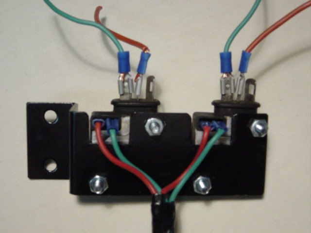
Cut and polished the aluminum plate, traced and drilled the holes for the igniters screws, as well as the holes for the wires going to the dizzy.
Covered the back of the igniters with the heat sink and placed them on the aluminum plate.
Ran the red wires from the negative side of the leading coils to the C blade, (-) of the leading igniters and the green wires from positive side of the coils to the B blade, (+) of the two leading igniters and then to the dizzy in the following manner.
Red wire (+) from G side on the back of the igniters to the red wire on the dizzy, I used a but connector from the electrical kit and some insulators to prevent the connection from getting wet.
I spliced the two G (+) connections, (red wires together on the back of the igniters plate, and connected them to the leading red wire coming from the dizzy�s magnetic pick up.
Did the same with the S (-) connetions. (green wires)
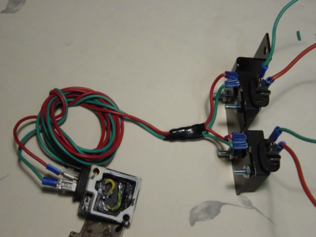
I used a jumper wire to power up all three coils. This wire runs from the back of the 30 amp relay.
The relay is connected in the following manner:
85 Switched 12 V from plug (red/blue)
12 V out to coils 30 87 12 V in from fuze box (red)
86 Ground (black)
For the trailing coil I ran two wires, red (-) & green (+), in the same manner as the leading as far as the color codes and the negative and positive are concern. Use the same blade connectors to plug into the trailing igniter, which sits on the right side of the plate as you look at it from the front.
After everything was connected I conducted a voltage test. Voltage is only going to be present on both sides, ( - & +) of all three coils and the B & C of the igniters, (were the plugs with boots go on).
I had to crank the car a couple of times and moved the distributor around to get it close to a timing reference. Once it fire up, I had to adjust the fuel/air mixture a bit. After adjusting the timing the car idles nice and easy. I accelerated it several times and it is obvious as to how much quicker it revs up. I will be placing a computer fan on the igniters plate to provide some cooling as they get extremely hot. The fan should provide for a longer life span of the igniters.


These are the parts I used:
80 dizzy
3 good igniters
3 MSD blaster coils
red & green wire (18 ga)
30 amps relay, (Radio Shack), Prt Number 275-0226
1 tube Heat sink
1 set Taylor custom wires, and 2ea Taylor repair kits,
(part # 409 Repair Kit 90/180 Boots 45963)
Some old connectors, igniters boots
Electrical repair kit, (plugs, connectors & insulators), wire stripers
1 piece of aluminum about 2.5 x 4 in
1 ground strap
custom brackets
I chose the 80 dizzy because the wires are long enough and it was laying around for another project with MSDs.
After looking at my crowded engine bay, I chose to place the trailing coil by the battery, since is the only place that I have enough room.
I placed both leading coils in the stock position and will make a bracket for the trailing coil.
I made two long (36") leading plug wires with the Taylor repair kit.
Ran the 30 AMPS relay hot wire from a 30 AMPS fuse on my added fuse block. (See pic below)
Ran the switched wire from the blue wire on the plug I found by the brake booster. (Looked it up on the Mazda repair manual and could not come up with anything).
Cut and polished the aluminum plate, traced and drilled the holes for the igniters screws, as well as the holes for the wires going to the dizzy.
Covered the back of the igniters with the heat sink and placed them on the aluminum plate.
Ran the red wires from the negative side of the leading coils to the C blade, (-) of the leading igniters and the green wires from positive side of the coils to the B blade, (+) of the two leading igniters and then to the dizzy in the following manner.
Red wire (+) from G side on the back of the igniters to the red wire on the dizzy, I used a but connector from the electrical kit and some insulators to prevent the connection from getting wet.
I spliced the two G (+) connections, (red wires together on the back of the igniters plate, and connected them to the leading red wire coming from the dizzy�s magnetic pick up.
Did the same with the S (-) connetions. (green wires)
I used a jumper wire to power up all three coils. This wire runs from the back of the 30 amp relay.
The relay is connected in the following manner:
85 Switched 12 V from plug (red/blue)
12 V out to coils 30 87 12 V in from fuze box (red)
86 Ground (black)
For the trailing coil I ran two wires, red (-) & green (+), in the same manner as the leading as far as the color codes and the negative and positive are concern. Use the same blade connectors to plug into the trailing igniter, which sits on the right side of the plate as you look at it from the front.
After everything was connected I conducted a voltage test. Voltage is only going to be present on both sides, ( - & +) of all three coils and the B & C of the igniters, (were the plugs with boots go on).
I had to crank the car a couple of times and moved the distributor around to get it close to a timing reference. Once it fire up, I had to adjust the fuel/air mixture a bit. After adjusting the timing the car idles nice and easy. I accelerated it several times and it is obvious as to how much quicker it revs up. I will be placing a computer fan on the igniters plate to provide some cooling as they get extremely hot. The fan should provide for a longer life span of the igniters.

Thanks!
Took it for a spin a while ago and it moves very good. I can step on it on four or fifth gear and with no hessitation it quickly picks up.
I did not like the fact that it take sa minute to start once is warm, but I think that once I put a fan on the igniters it will stop doing that.
I did not like the fact that it take sa minute to start once is warm, but I think that once I put a fan on the igniters it will stop doing that.
First of all I want to thank those for taking the time to share their knowledge with fellow members and for taking the time to post informative information such as this that will help members in the future.
I did this upgrade to my Gsl-Se and will share where I mounted it (have A/C) and the little differences that I did in wiring and such so to give to members options and ideas in performing this upgrade.
I left the leading coil in it's original home and did not do anything with the trailing ignitor as it is left in it's original spot also.
I mounted the 2nd leading coil as seen using a fence post clamp ($1.29 at the local hardware store.) I relocated my fuse assembly to the shock tower facing the engine. I also mounted my relay in the same hole as the bolt that secures the clamp holding the coil in place. It is the existing hole that held the fuse assembly in place.
As seen I mounted the ignitor's on a piece of aluminum and attached it to the strut tower bolts. Instead of using a dremel tool to make access to the ignitor wires I simply mounted them towards the top outside of the sluminum and used scissors to notch a opening for them.
I wanted to keep things as clean and simple as possible with the wiring so it did not look like I had wiring everywhere. So as seen I kept all the components as close as possible. Instead of gutting an ignitor I used the existing connections at the distributor from the magnetic pick up to the back of the ignitors. I also used the existing switched on power source (black with yellow stripe wire) that normally goes to the top of the leading ignitor. I ran that wire to the switched on terminal at the relay. I taped off the other side of the black with yellow stripe wire that originally went to the leading coil + side. It is not being used and you do not want a live wire just dangling around.
Ran my relay the same as leknaw69 using the fuse panel hot wire that comes from the battery as my 12V power source for the relay. Ran the ground wire from the # 86 spot on the relay to the existing bolt that holds the coils in place.
Again my switched power source is from the original black with yellow stripe wire that is at the stock leading ignitor location as seen in the picture. My 12V output wire from the relay goes to the + side of the leading coil and is jumpered to the 2nd leading coil.
I am also using the stock 2nd gen ignition wires. They are long enough to go from the coil locations to the spark splugs.
If anyone has anymore questions regarding this installation please post them up as this thread is going to be streamlined and archived for future reference.
Here are some pictures that show where and how I mounted and wired.
Last edited by Rx-7Doctor; May 27, 2009 at 05:20 PM.
leknaw69, you never said anything about an '80 dizzy in your PMs. They have a reversed reluctor. That's why your timing was off at first. Let me guess; something like 20 degrees? That also explains your trouble with the trailing ignitor (as there is no spot for them on the '80 dizzy).
Glad you figured it out and got it running. Have fun!
Glad you figured it out and got it running. Have fun!
80's dizzy
leknaw69, you never said anything about an '80 dizzy in your PMs. They have a reversed reluctor. That's why your timing was off at first. Let me guess; something like 20 degrees? That also explains your trouble with the trailing ignitor (as there is no spot for them on the '80 dizzy).
Glad you figured it out and got it running. Have fun!
Glad you figured it out and got it running. Have fun!
Nice work, clean install.
I just dont see the benefit of doing this when you can use one ignitor to fire a FC coil for the same setup. I am not bashing it though.
I just dont see the benefit of doing this when you can use one ignitor to fire a FC coil for the same setup. I am not bashing it though.
benefit
It sure is an improvement over the stock set-up. My main reason for choosing this set up is somewhat the uniqueness of it. I have one of the other setups and it is just to bulky for the room I have in my engine bay.
DLIDFIS will give you hotter spark than a direct fire using FC coil connected to the stock leading igniter. In fact, a DLIDFIS will run as good as using a MSD 6A or 6AL. I have no other electronic devices to prove this but you have to look at the flashes from a timing gun.
Yes, of course both leading plugs spark at the same time with DLIDFIS. The sparks can be hotter than an FC coil because each plug has a dedicated coil and is driven by a dedicated ignitor. The only thing really "shared" on a DLIDFIS setup is the pickup signal, but it has no bearing on spark strength as it mearly tells the ignitors when to fire. The actual voltage and duration are controlled by the ignitor (which can be upgraded to a GM HEI) and the spark plug gap and whether it's compressed and/or ionised in the combustion chamber, depending on conditions. Increase the gap or otherwise make it more difficult for the spark to jump, and it will become hotter as a rule. The same can be said for the FC coil, as both are a kettering system. I just like DLIDFIS more because the coils are two separate entities and have a higher performance potential if driven properly.
I don't know if that really answers your question. I haven't thought about this stuff in a long time.
I don't know if that really answers your question. I haven't thought about this stuff in a long time.
Joined: Jul 2002
Posts: 7,301
Likes: 3
From: District of Columbia
don't forget the awesomeness when driving the FC coil with an ignition box. mine is getting a crane to drive it soon. 520Vat the coil! Gas mileage here I come. I'm not going to get lean surge at 16:1 
Exactly. Way better than driving two coils from one box. CDI = 2nd gen coil. Kettering = DLIDFIS.
Adrian, do you think a new ignition and maybe a 2.5 to 4" collecter will get you to the magical 200 hp mark? It'd be cool if that's all it takes to get there.
Adrian, do you think a new ignition and maybe a 2.5 to 4" collecter will get you to the magical 200 hp mark? It'd be cool if that's all it takes to get there.
Lives on the Forum
Joined: Jun 2004
Posts: 11,359
Likes: 14
From: Grand Rapids Michigan
Okay, I'm not sure I understand your explanation but I'll buy it for now. 
I do know that my car performed unbelievably well when running the Transistor Trick. I really miss that, but it has a tendancy to eat up the 2nd gen ignitors/resistors. One of these days I'll figure out the workaround that Bad83 is using. But man, did that ever free up some horses...
I do know that my car performed unbelievably well when running the Transistor Trick. I really miss that, but it has a tendancy to eat up the 2nd gen ignitors/resistors. One of these days I'll figure out the workaround that Bad83 is using. But man, did that ever free up some horses...
Yes, of course both leading plugs spark at the same time with DLIDFIS. The sparks can be hotter than an FC coil because each plug has a dedicated coil and is driven by a dedicated ignitor. The only thing really "shared" on a DLIDFIS setup is the pickup signal, but it has no bearing on spark strength as it mearly tells the ignitors when to fire. The actual voltage and duration are controlled by the ignitor (which can be upgraded to a GM HEI) and the spark plug gap and whether it's compressed and/or ionised in the combustion chamber, depending on conditions. Increase the gap or otherwise make it more difficult for the spark to jump, and it will become hotter as a rule. The same can be said for the FC coil, as both are a kettering system. I just like DLIDFIS more because the coils are two separate entities and have a higher performance potential if driven properly.
I don't know if that really answers your question. I haven't thought about this stuff in a long time.
I don't know if that really answers your question. I haven't thought about this stuff in a long time.
Joined: Jul 2002
Posts: 7,301
Likes: 3
From: District of Columbia
Uh I don't think so. I think I'm running out of air flow from the 43mm chokes in the carb. Bigger chokes or just swapping to a 51IDA should do it. I think changing the collector would net more midrange tq at peak flow it might be a little different.