
85 GSL-SE tape deck pinout ponderance...*PICS*

Thread Starter
irritating nuisance
iTrader: (1)
Joined: Dec 2010
Posts: 252
Likes: 3
From: Central PA
Thanks guys, but I'm quite aware of FM modulators. And IMO they suck. Just not as bad as a tape adapter. 
RF modulators are a solution, but you're limited to the frequency response of your tuner, in our case 27 year old tuners... piggybacking the input signal on the tape channel is much cleaner. Another consideration if you're on a budget is that this mod is nearly free.
ioTus: You likely won't hear any audiophile anywhere debating rf modulators
Rotor Venom: You're a dumb ***. A 5 second search for a crappy RF modulator that they won't even post the specs on?
Do you realize how little sense that sentence makes? So it won't interfere with any noise huh... um hokay  . One crappy ground and it most certainly will induce noise into the system. The aux-in mod is clean, nearly free, and doesn't require any 12v or ground wires. Not to mention it completely bypasses the tuner section of the HU. And if you critically THINK and USE THE FSM diagrams there's no "tearing apart" of the system involved. The hard work of determining the color coding of the DIN cables has already been done. A screwdriver, wire strippers and electrical are about all you need. Your welcome.
RF modulators are a solution, but you're limited to the frequency response of your tuner, in our case 27 year old tuners... piggybacking the input signal on the tape channel is much cleaner. Another consideration if you're on a budget is that this mod is nearly free.
ioTus: You likely won't hear any audiophile anywhere debating rf modulators
Rotor Venom: You're a dumb ***. A 5 second search for a crappy RF modulator that they won't even post the specs on?
. One crappy ground and it most certainly will induce noise into the system. The aux-in mod is clean, nearly free, and doesn't require any 12v or ground wires. Not to mention it completely bypasses the tuner section of the HU. And if you critically THINK and USE THE FSM diagrams there's no "tearing apart" of the system involved. The hard work of determining the color coding of the DIN cables has already been done. A screwdriver, wire strippers and electrical are about all you need. Your welcome.
So I guess I thought this was sending a direct line-in over the antennae cable - not some shmancy RF modulation.
I think what I may do is a write-up on wiring in a USB charger / aux input panel so we wont need debate about it. I'm thinking of pulling the fader joystick and dropping the panel into that slot.
I'll have to investigate a little more how that whole wiring sitch looks - seems the joystick adds a little funky-ness to the whole thang.
First thing's first though - I need to get a factory radio! My hook up hasn't come through yet. My car looks seriously ghetto with a gaping hole where there once was a radio....
my buddys a wrecker driver and snatched one out of some drunk guys car. works awesome and cost me NOTHING. take that internet engineering. (shakes fists)
 lol
lol
Last edited by Rotor_Venom08; Jan 24, 2013 at 08:33 PM.
Thread Starter
irritating nuisance
iTrader: (1)
Joined: Dec 2010
Posts: 252
Likes: 3
From: Central PA
ive got the clarion 3 piece head unit that came out of my gsl. its all works EXCEPT THE TAPE DECK. mainly the reason why i didn't entertain the idea of hard wiring anything into a box of scrap. or buy the listed item, or comparable was because my tape deck was Blooey. never worked.
my buddys a wrecker driver and snatched one out of some drunk guys car. works awesome and cost me NOTHING. take that internet engineering. (shakes fists) lol
my buddys a wrecker driver and snatched one out of some drunk guys car. works awesome and cost me NOTHING. take that internet engineering. (shakes fists)
lolIf the deck still powers up u might be able to sell it to someone looking to restore. You should still be able to hijack the channel the tape puts out over. Btw the input will be heard regardless of source, if you use the tuner you'll hear your aux source mixed with the radio. Once you insert a tape ( just the shell of a tape) it'll mute the tuner. It sounds like your deck is shot but the channel should still be open. in your case you could skip the tape deck and inject into the tape output to the eq. Might be an issue w/ muting your tuner tho if the deck is totally dead/ without power. Btw sorry for the snippy response before, long day...

Thread Starter
irritating nuisance
iTrader: (1)
Joined: Dec 2010
Posts: 252
Likes: 3
From: Central PA
So I guess I thought this was sending a direct line-in over the antennae cable - not some shmancy RF modulation.
I think what I may do is a write-up on wiring in a USB charger / aux input panel so we wont need debate about it. I'm thinking of pulling the fader joystick and dropping the panel into that slot.
I'll have to investigate a little more how that whole wiring sitch looks - seems the joystick adds a little funky-ness to the whole thang.
First thing's first though - I need to get a factory radio! My hook up hasn't come through yet. My car looks seriously ghetto with a gaping hole where there once was a radio....
I think what I may do is a write-up on wiring in a USB charger / aux input panel so we wont need debate about it. I'm thinking of pulling the fader joystick and dropping the panel into that slot.
I'll have to investigate a little more how that whole wiring sitch looks - seems the joystick adds a little funky-ness to the whole thang.
First thing's first though - I need to get a factory radio! My hook up hasn't come through yet. My car looks seriously ghetto with a gaping hole where there once was a radio....
I hate that stipid joystick too. Aside from being easily bumped it's a completely redundant gimmick BAD MAZDA!
Good luck w the usb mod. Im likely gonna pull the Atari controller and replace it w a typical phono jack as the line in.
Maybe Venom can sell you his if the deck powers up?
I hate that stipid joystick too. Aside from being easily bumped it's a completely redundant gimmick BAD MAZDA!
Good luck w the usb mod. Im likely gonna pull the Atari controller and replace it w a typical phono jack as the line in.
Thread Starter
irritating nuisance
iTrader: (1)
Joined: Dec 2010
Posts: 252
Likes: 3
From: Central PA
OK so i'm trying to wrap my head around this - Factory head unit is NOT amplified - it sends its signal out to two Clarion amps which in turn power the speakers.
SO output from the headunit is going to be line-level (pre-amplified), correct? Not speaker-level (post amplified).
What are the signal wires like when they connect to the factory amps, RCA, straight cable, proprietary plug?
Just picked up a set of Focal ic130 (5.25") and ic165 (6.75") and will be ordering a JL XD700/5 amp to push them. I won't divulge my devious plans for subwoofers yet though
A great thing about the JL higher end amps is they will take both line- and speaker-level input, so I'm covered either way. However I do need to get a speaker cable to RCA plug adapter as the amp still takes RCA input on speaker-level.
Its cool man if I got upset with every internet ego that insulted me I'd have no time to save the world. Lol its a dirty job but someone has to do it.
As far as the radio goes it does work and powers up all the wiring is intact it will actually go.into "tape mode" and cut the radio but you can't hear anything.
I would entertain the idea of selling it but wanted it just in case I sold my car plus there's a tape of the Mormon tabernacle choir stuck in there that's a bonus... don't ask me how that happened...
Does the deck power up at all or is it completely dead?
If the deck still powers up u might be able to sell it to someone looking to restore. You should still be able to hijack the channel the tape puts out over. Btw the input will be heard regardless of source, if you use the tuner you'll hear your aux source mixed with the radio. Once you insert a tape ( just the shell of a tape) it'll mute the tuner. It sounds like your deck is shot but the channel should still be open. in your case you could skip the tape deck and inject into the tape output to the eq. Might be an issue w/ muting your tuner tho if the deck is totally dead/ without power. Btw sorry for the snippy response before, long day...
If the deck still powers up u might be able to sell it to someone looking to restore. You should still be able to hijack the channel the tape puts out over. Btw the input will be heard regardless of source, if you use the tuner you'll hear your aux source mixed with the radio. Once you insert a tape ( just the shell of a tape) it'll mute the tuner. It sounds like your deck is shot but the channel should still be open. in your case you could skip the tape deck and inject into the tape output to the eq. Might be an issue w/ muting your tuner tho if the deck is totally dead/ without power. Btw sorry for the snippy response before, long day...
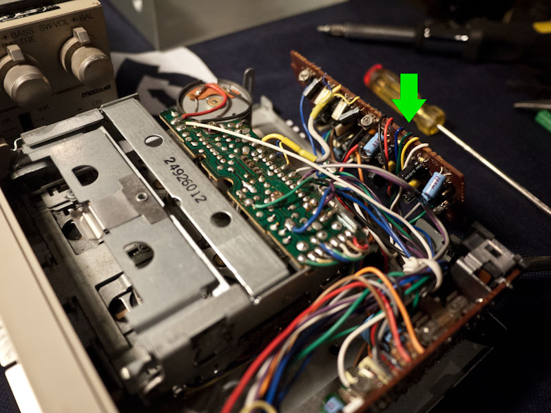
You can do that, or you can take the cover off the component that cable(the one you're tapping into)runs into. Then follow where those pins go on the other side of the back inside and tap into those at either end. I think...It's been a while.
Follow the wires you want to tap into to the end of that cable. See what pins they are in the cable end to determine what pins they go to on the tape deck connector when they are mated. Take the cover(top) off of the tape deck and see where the pins you've identified on the OUTside of tape deck go on the INside of the deck. Then attach at the end of those wires, or the back(inside) of the plug connector. Make any more sense? If not, I'll dig up some pics...
Thread Starter
irritating nuisance
iTrader: (1)
Joined: Dec 2010
Posts: 252
Likes: 3
From: Central PA
I just sliced the black encasing wire carefully to access the wires inside. Then I carefully slid some insulation away of the wires I needed to access them without damaging them. Even if you cut the wires you can always splice them back, but then you start having different lengths of wire and the bundle starts getting messy.
Follow the wires you want to tap into to the end of that cable. See what pins they are in the cable end to determine what pins they go to on the tape deck connector when they are mated. Take the cover(top) off of the tape deck and see where the pins you've identified on the OUTside of tape deck go on the INside of the deck. Then attach at the end of those wires, or the back(inside) of the plug connector. Make any more sense? If not, I'll dig up some pics...
Yes, I would wire to the inside of the tape deck. I have pics somewhere, but I never actually installed anything permanent. I want to incorporate an old mp3 player into the center console and then finalize all the wiring...A few years ago I messed around testing to figure out how to hard wire the aux in, but never went any further...I need another center console for sacrifice...
ive got the clarion 3 piece head unit that came out of my gsl. its all works EXCEPT THE TAPE DECK. mainly the reason why i didn't entertain the idea of hard wiring anything into a box of scrap. or buy the listed item, or comparable was because my tape deck was Blooey. never worked.
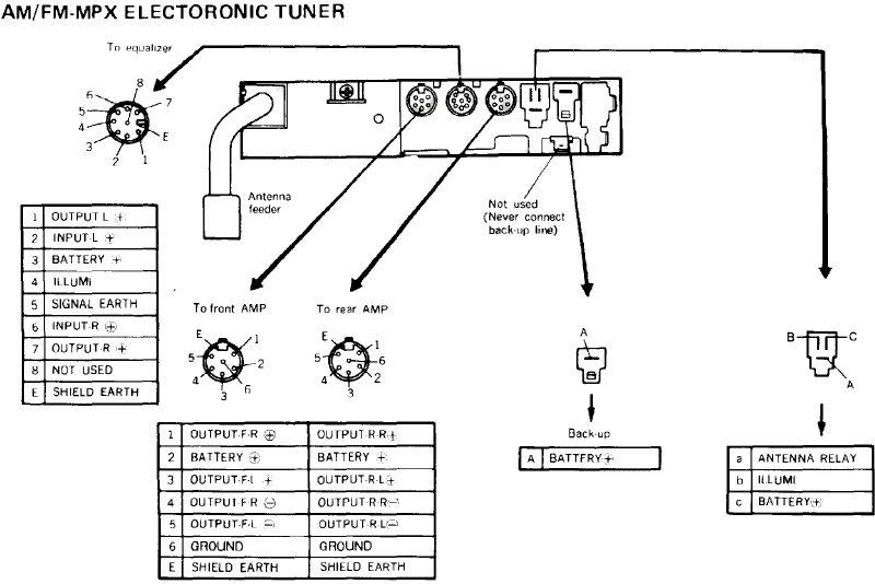
OK so for the past few days I've been poring over the FSM section on the factory stereo system (1985 - Body Electrical - pp 62-78). And, with the help of Mr. Johnny "Stale" Cracker, I think we've almost got it figured out.
So, as you're probably aware, the 3 units are daisy chained together. End-of-the-line is the Tape deck:
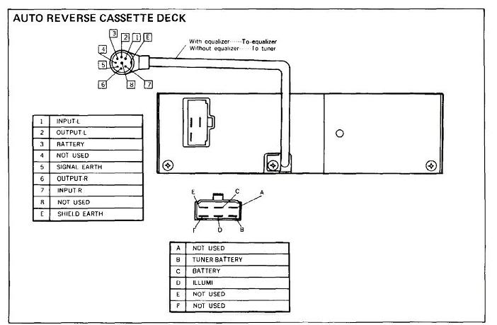
which then sends ONLY output to the EQ (as stated previously, Tape Deck "inputs" go to "not used" on the EQ, meaning that it's routed in through the tape deck PCB to the tape deck "outputs")
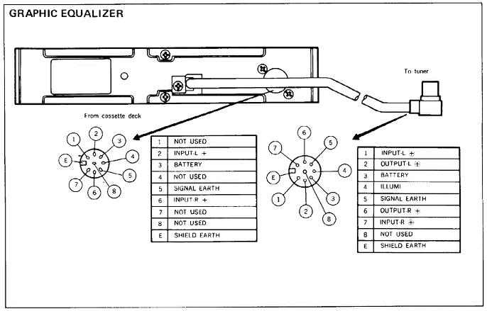
The EQ and the Receiver then talk back and forth (obviously - if you're going to EQ the radio output it has to route through the EQ). The EQ is always on, otherwise it wouldn't be able to pass through tape signal to receiver. "Defeat" simply bypasses the circuit array of EQ's. The tape deck still has to pass through the signal for the receiver to power down.
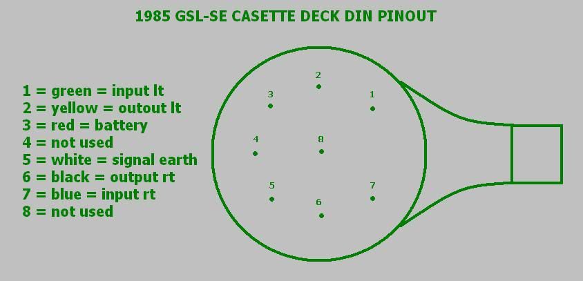
Now, after wrapping my braens around how the signal was being passed back and forth, I took another look at the pinouts. Well, we know what Input is, we know what output is, those are signal lines. Battery - obviously main power for the unit. Shield Earth - obviously the unit's ground circuit. Pin 5 - hmmmm Signal Earth. Wait a tick - that's the Little Blue line that you send to an amplifier to tell it to turn on .... OR off.
That's gotta be it - that must be what sends the signal to the receiver to tell it to shut off when a tape is inserted. There are no other pins for the tape deck to communicate with the receiver.
The tape deck mechanism is relatively simple - when a tape is inserted it drops down the cage which has a lever in the back that pushes a button, switching the PCB and all related componentry on. When you push "Stop" it pops the tape out, releases the button, and disconnects the PCB. Basically, when the tape is in, it sends "Signal Earth" THROUGH the EQ and up to the Receiver. Check Pin-5 on each of the cables - same the whole way through.
So what I'm thinking at this point, all we need is a relay switch between one of the Inputs and the Signal Earth. Relay switch senses Input signal - trips the Signal Earth and turns off the Receiver.
As we see below - Signal Earth is white and Inputs are blue and green. These points are easily identifiable on the PCB - the wires go straight out of the cable to contact points. I have a pic at home I will post later:
I will be bench testing this in the next week and verify what state the Signal Earth is when a tape is inserted. I will also be verifying tape deck Outputs to determine what sort of a signal the Inputs are expecting (assuming its a direct pass-through circuit, which it seems from what others have posted it is).
Please read through and see if you can find any flaws in the logic here. I think we're close to cracking this wide open, at which point the possibilities get exciting
~Geoff
Side note: has anyone noticed that the FSM diagrams show the units upside-down??
So, as you're probably aware, the 3 units are daisy chained together. End-of-the-line is the Tape deck:
which then sends ONLY output to the EQ (as stated previously, Tape Deck "inputs" go to "not used" on the EQ, meaning that it's routed in through the tape deck PCB to the tape deck "outputs")
The EQ and the Receiver then talk back and forth (obviously - if you're going to EQ the radio output it has to route through the EQ). The EQ is always on, otherwise it wouldn't be able to pass through tape signal to receiver. "Defeat" simply bypasses the circuit array of EQ's. The tape deck still has to pass through the signal for the receiver to power down.
Now, after wrapping my braens around how the signal was being passed back and forth, I took another look at the pinouts. Well, we know what Input is, we know what output is, those are signal lines. Battery - obviously main power for the unit. Shield Earth - obviously the unit's ground circuit. Pin 5 - hmmmm Signal Earth. Wait a tick - that's the Little Blue line that you send to an amplifier to tell it to turn on .... OR off.
That's gotta be it - that must be what sends the signal to the receiver to tell it to shut off when a tape is inserted. There are no other pins for the tape deck to communicate with the receiver.
The tape deck mechanism is relatively simple - when a tape is inserted it drops down the cage which has a lever in the back that pushes a button, switching the PCB and all related componentry on. When you push "Stop" it pops the tape out, releases the button, and disconnects the PCB. Basically, when the tape is in, it sends "Signal Earth" THROUGH the EQ and up to the Receiver. Check Pin-5 on each of the cables - same the whole way through.
So what I'm thinking at this point, all we need is a relay switch between one of the Inputs and the Signal Earth. Relay switch senses Input signal - trips the Signal Earth and turns off the Receiver.
As we see below - Signal Earth is white and Inputs are blue and green. These points are easily identifiable on the PCB - the wires go straight out of the cable to contact points. I have a pic at home I will post later:
I will be bench testing this in the next week and verify what state the Signal Earth is when a tape is inserted. I will also be verifying tape deck Outputs to determine what sort of a signal the Inputs are expecting (assuming its a direct pass-through circuit, which it seems from what others have posted it is).
Please read through and see if you can find any flaws in the logic here. I think we're close to cracking this wide open, at which point the possibilities get exciting
~Geoff
Side note: has anyone noticed that the FSM diagrams show the units upside-down??
OK so i'm giving up on the signal-sensing override of the radio headunit. I've decided I like the old-skool factor of having to push a tape into the deck.
I'm going to get some flouro-pink and baby-blue tape straight out of hte 80's, remove the wheels, and use it as a big "play" button.
Now I'm just trying to get the highest quality input / output.
Came across this today:
Pac-Audio.com Product Details | iPod Integration for your car and More by Pac-Audio - Connecting you to the future
Dual RCA-in, single-RCA output. Take the signal going from the head unit to the amp, take a signal from an Aux Input. This theorhetically will switch the inputs when it senses your Aux is live.
However - still the same issue I came up against with the idea of turning off the radio - what happens in between tracks or during silent parts of a song? Will the radio turn back on, then cut out when the epic trance drop finally comes back in???

While I am not an audio expert, I believe that ther.e will still be a signal from your AUX source even between tracks or quiet parts of a song
Update: I do believe i have found the correct power routing that switches the radio unit on and off. It is NOT through the DIN connectors as i previously thought.
( note pin-letter capitalization in reference to diagrams )
The main audio system stack's power is recieved through the tape deck harness connector - pin "C - battery"
When the tape deck is off (tape is ejected), power is routed through the tape deck, pin "B - tuner battery", to the radio tuner, pin "c - battery (+)"
- This allows the radio to turn on and function by pressing the power / volume button
When the tape is inserted, power to pin "B - tuner battery" is interrupted, and the harness plug for the radio tuner pin "c - battery (+)" no longer recieves signal.
SO theorhetically - i havent tried this out yet, but let me think out loud here - if we have a signal-sensing relay for an audio line input, we could use that to close the circuit between constant battery 12v and the EQ.
further experimentation is required to decipher the remainder of the audio system switching.
my questions are:
> Can you pass an "input" through the system with both the tuner, tape deck, and EQ off? (will determine nature of tuner's output & volume / EQ / balance circuits)
if yes then
> Can you pass an "input" through with EQ on and tuner & tape deck off?
Thanks for the time/effort on the subject, I know I appreciate it, and it has inspired me to finally git "it" done with my car..."It" being incorporating an older mp3 player into my center console and wiring it so that once I plug it into place, it will get re-charge current, and trip the radio off into "input" mode. I'll have no need for playing tapes anymore, so I'll wire into the little switch inside the tape deck that senses when a tape is inserted(Unless you DO confirm your theory on the non-din solution). (Of course, I could still insert a tape and listen to it as normal if I don't play anything from the mp3 player). It'll be a while as my car is still in "winter storage" for an undetermined amount of time this year...
I know IF the radio is off(hence also the tape deck and EQ) and you trigger the switch inside the tape deck, it WILL power the EQ and the amps, and not the radio. If you trigger "tape deck" mode with radio off, EQ and amps will power on, and it IS basically passing an "input" through with EQ on and tuner and tape deck off. Don't know if this is exactly what you wanted to know, hope it helps. Keep us updated.
I know IF the radio is off(hence also the tape deck and EQ) and you trigger the switch inside the tape deck, it WILL power the EQ and the amps, and not the radio. If you trigger "tape deck" mode with radio off, EQ and amps will power on, and it IS basically passing an "input" through with EQ on and tuner and tape deck off. Don't know if this is exactly what you wanted to know, hope it helps. Keep us updated.
I've been searching for a way to play my iPod through my factory GSL-SE stereo (other than the cassette adaptor and FM modulator). I knew there were unused inputs to the cassette from looking at the FSM schematics but never figured out how they worked.
Then I found this thread. This afternoon I installed and wired a bulkhead-style mini headphone jack on the back panel of the cassette deck and ran a headphone extension cable from it out to the console. I gutted a cassette tape to stick into the cassette player and my iPod works great in my old Mazda.
Thank you, thank you, thank you!!!!!!!

Junior Member
Joined: Aug 2015
Posts: 19
Likes: 0
From: Dripping Springs, TX
This is a very interesting and helpful thread, but I'm not a very technical guy and I'm not sure if there was a conclusion as to the best way to wire in an MP3 player. Do you simply tap into the wires in the cassette player? If so, is it simply Input L and Input R? Did anyone write a tutorial? Any tips or further input would be appreciated.