Megasquirt V3.0 MS Build With Pics
 04-27-06, 10:05 PM
#1
Rotary Enthusiast
Thread Starter

V3.0 MS Build With Pics
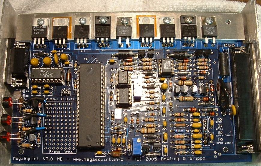
I just finished another MS build tonight. This one is V3.0, for TII use, stock FC ignition, 24-2 style modified CAS, and 3-bar MAP sensor. It tests fine on the stim, so I'm hoping all is well. I'll power up my test bench later, and test with an actual 24-2 style CAS just to be sure.
All wiring is via DB-37, no extra connectors needed. This is my first V3.0 build, although I've built several V2.2 and earlier styles. V2.2 is a much easier build, as the board is less populated, and pad spacing, particularly on the little NPN transistors, is much more generous. Those of you that have built V3.0 units before, let me know if anything looks odd.
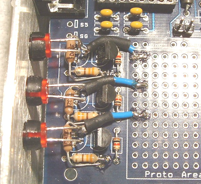
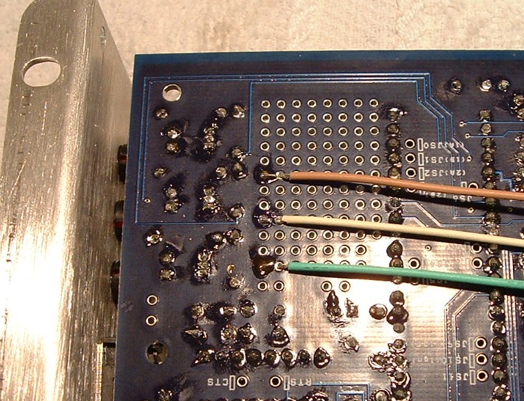
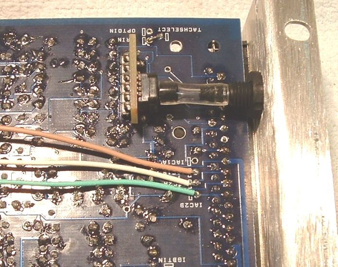
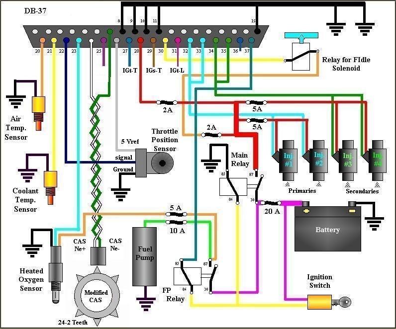
The only modification made to the board is the addition of the three pull-up resistors (those brown 'DALE' resistors seen running vertical in the first couple pics), and associated wiring to bring the ignition signals out the DB37. See attached pics for details. I used the prototype area as a pass-through, to get from the top to bottom side of the board, and ran the wires along the underside. The wiring should match the attached wiring schematic.
All wiring is via DB-37, no extra connectors needed. This is my first V3.0 build, although I've built several V2.2 and earlier styles. V2.2 is a much easier build, as the board is less populated, and pad spacing, particularly on the little NPN transistors, is much more generous. Those of you that have built V3.0 units before, let me know if anything looks odd.
The only modification made to the board is the addition of the three pull-up resistors (those brown 'DALE' resistors seen running vertical in the first couple pics), and associated wiring to bring the ignition signals out the DB37. See attached pics for details. I used the prototype area as a pass-through, to get from the top to bottom side of the board, and ran the wires along the underside. The wiring should match the attached wiring schematic.
Last edited by muythaibxr; 06-18-06 at 08:22 AM.
 04-27-06, 10:51 PM
#2
MegaSquirt Mod
Hey Renns, one thing you might want to be careful with using the 12-1 (24-2) setup, especially with the built-in VR sensor conditioner is noise. The missing tooth decoder is a lot more sensitive to noise so far in my experience (using 12-1 in my 20 valve 4age on the ae86, and from what people using it that way have been telling me about their setups). I've had to do a lot to clean up EMI on the signal wires, make extra sure my grounds are good, make sure my relay grounds for various relay-driven components are separate from my MS grounds, and I've had to tinker with the threshold Potentiometer on the MS. All that to get rid of a small amount of noise right at 6800-7000 rpms where the relay I'm running my VVT with turns off.
04-28-06, 05:49 AM
#3
Rotary Enthusiast
Thread Starter
Are you saying the 12-1 is more susceptible to noise than the using the stock CAS? I'm not clear on that, as the input hardware is identical with missing tooth and 2nd trigger. Did you mean the V3.0 built-in VR circuit is more susceptible to noise than the LM1815 circuit? That I can see, given the adaptive hysteresis feature of that chip. Hopefully with the proper grounds and shielding you mention, and following the VR circuit pot adjustment procedures here the install will run smoothly.
Hopefully these pics clarify the board mods required to support ignition output. Feel free to add these pic(s) to the FAQ if you like to supplement that older V2.2 board pic.
Hopefully these pics clarify the board mods required to support ignition output. Feel free to add these pic(s) to the FAQ if you like to supplement that older V2.2 board pic.
04-28-06, 07:49 AM
#4
Senior Member

Join Date: May 2002
Location: FL
Posts: 386
Likes: 0
Received 0 Likes
on
0 Posts
I've found the VR wiring to be the most important part in order to assure a noise-free signal. I've had zero problems using that intercom wire I've spoken of previously (twisted pair inside a braid and foil shield) as well as meticulous attention to being certain everything electrically connected is directly connected to a unified ground. This is regarding the v3 VR circuit. I've never had much luck with the 1815 circuits, I think primarily due to a 50KW AM radio station antenna 1/2 mile away from my home workshop. They work fine as soon as I get away from that antenna. With a scope, I can see the AM signal in the inputs and it seems to confuse the 1815 in some way.
-Mike
-Mike
04-28-06, 09:24 AM
#5
MegaSquirt Mod
What I'm saying is that the noise is more harmful to the missing tooth wheel decoder than it is to the 2nd trigger decoder. I say this because:
1) If noise is keeping the MS from seeing the missing tooth at all, you won't ever get sync
2) Once you're synced, if noise makes the MS not see the missing tooth, you'll get ignition misses
3) If you have a lot of random noise at one point or another, it's easier to get nasty tach-spikes... I've seen as high as 20000 rpms when I'm really only at 6800.
You can still get misses on the 2nd trigger wheel decoder if the Ne conditioner gets more pulses than it should... and you can still get tach spikes if the G conditioner gets more pulses than it should, but in my experience, this doesn't happen as often, even with a slightly noisy signal. I've seen cases where the stock CAS works fine, but using the same wiring the missing tooth decoder doesn't.
I'll probably use your pics, as well as take a few of my own.
I also used that link you posted when adjusting my VR sensor conditioner. I haven't quite finished adjusting that however. I adjusted it on the car while it was running once, and got rid of the 6800 rpm spike, but then the car wouldn't start when I cranked it. When I adjusted it back 3 turns, it worked fine on crank, but the 6800 rpm problem came back.
So now I'm working on moving my relay ground somewhere other than where the MS is grounded. I'm pretty sure this isn't EMI coming in over the VR wires because 1) it doesn't happen anywhere but 6800 rpms and 2) datalogging shows that my output1 (relay for VVT) is turning off excactly where I have spikes/drops. I had those relays sharing the exact same ground point on the engine, as well as sharing the same +12v as the injectors and ignitors (I calculated what would be needed for both, and the thickness of wire I chose should be good), so I think it's just the fact that my grounds are shared between the MS and the relays. I all but got rid of the problem by running my transistor circuit grounds to a spot on the power ground plane in the MS instead of the logic ground plane (haven't gotten any spikes, just a few drops, which suggests that I've greatly reduced the noise).
With an lm1815 I probably wouldn't have to even worry about this as it has adaptive filtering, so noise probably wouldn't even register unless it was very strong noise. With the dual trigger decoder, with the G signal on an lm1815, this noise would cause misses, which is what I'm seeing now, It wouldn't be likely to cause spikes because the decoder would just lose sync, where with the missing tooth decoder, I would either lose sync, or the decoder would detect false missing teeth in the noise, and try to decode based on that, giving me weird spikes to 10000-20000 rpms.
Last edited by muythaibxr; 04-28-06 at 09:47 AM.
04-28-06, 05:23 PM
#6
Rotary Enthusiast
Thread Starter
Originally Posted by pmrobert
I've found the VR wiring to be the most important part in order to assure a noise-free signal. I've had zero problems using that intercom wire I've spoken of previously (twisted pair inside a braid and foil shield) as well as meticulous attention to being certain everything electrically connected is directly connected to a unified ground. This is regarding the v3 VR circuit. I've never had much luck with the 1815 circuits, I think primarily due to a 50KW AM radio station antenna 1/2 mile away from my home workshop. They work fine as soon as I get away from that antenna. With a scope, I can see the AM signal in the inputs and it seems to confuse the 1815 in some way.
04-28-06, 10:16 PM
#7
MegaSquirt Mod
Well, like I said, with the missing tooth, because of the way it "resets" the tooth count, you have to be extra sure you have no noise when compared with the 2 sensor setup. My warning was mainly to make sure you take extra care with the wiring.
Trending Topics
04-28-06, 11:31 PM
#8
Rotary Enthusiast
Thread Starter
Ken,
Which relay are you referring to with your grounding problems? Sounds odd to me that you'd need to move to a separate location on the engine. Is your main battery-engine ground cable clean and secure, and are your MS ground wires of adequate size? You are right, grounding is certainly a common problem, even with the stock vehicles.
I've had good luck by running the top row DB37 grounds to one big (#8/10) ground wire, which terminates on a brass ground bolt on the firewall. On the engine side of the firewall, I continue the run of #8 wire from the brass bolt onto the intake. I'm not certain this is best practice, but it falls into the 'it works for me' category for my two MS'd vehicles.
04-29-06, 08:12 AM
#9
MegaSquirt Mod
I'm not even sure I'm *having* grounding problems. I have a relay that turns on/off my VVT solenoid. Right around where that relay turns off, I intermittantly get an engine stutter. Whenever I get that stutter, I can go look in the datalogs and find a very small tach dropout (which means there is a little noise around that area). The only thing I'm doing at 6800-7000 rpms is turning off the VVT relay, which means somehow I guess the flyback from turning off that relay is getting into my MS and causing noise on the VR sensor conditioner.
I grounded my MS pretty much the same way you did, all my grounds are clean, etc. I didn't ground to the firewall first... I went straight to the engine, and the engine grounds to the chassis, but I doubt very seriously that my grounds are causing this problem.
When I don't use the VVT, I don't get this noise issue, it only happens when I'm using the VVT, so I'm sure I've wired that relay or the solenoid in such a way that I'm causing the noise somehow. So I'm going to rewire that relay... Right now I'm pretty sure I'm powering it from the same wire that powers the MS, and the MS of course is the ground for it. I'm going to find another place that turns on whenever the main relay turns on, and power it from there.
But yeah, all my grounds are secure, and the engine runs perfect everywhere except 6800 rpms. I guess it's possible that when the relay is turning off, I'm introducing noise on the +12v side... Maybe I'll try putting another capacitor from the +12v to ground.
Last edited by muythaibxr; 04-29-06 at 08:15 AM.
04-29-06, 10:59 AM
#10
Rotary Enthusiast
Thread Starter
Ken,
If you haven't already done so, stick a flyback diode reversed across the terminals of the VVT solenoid. Put it right at the solenoid, not back in the harness somewhere. That might be all you need to solve the problem.
If you haven't already done so, stick a flyback diode reversed across the terminals of the VVT solenoid. Put it right at the solenoid, not back in the harness somewhere. That might be all you need to solve the problem.
04-30-06, 10:15 AM
#11
MegaSquirt Mod
I've got a flyback diode inside the MS. I don't think the solenoid is causing flyback into the MS, I think it's more likely the relay as that's what's directly connected. Maybe I'll try putting diodes in both places... although it'll be a bit ugly to have a random diode in the harness... especially since if I rewire it, that diode won't be necessary...
I really think at this point that it's b/c I have the relay coil that turns VVT on and off powered on the same wire that the MS gets power from. Anyway, I'll try all of the above later this week probably.
I really think at this point that it's b/c I have the relay coil that turns VVT on and off powered on the same wire that the MS gets power from. Anyway, I'll try all of the above later this week probably.
05-02-06, 11:06 AM
#12
how I missed this thread yesterday, I'm not really sure.
Looks awesome roger I can't wait to get the car running.
As far as engine-battery and chassis-battery grounding go I can assure all of you that it is a non-issue with this car, I have a 2/0AWG cable running from the negative terminal to the engine and 4GA cable running from the negative terminal to the chassis, both are new, clean and properly done.
Looks awesome roger
I can't wait to get the car running.As far as engine-battery and chassis-battery grounding go I can assure all of you that it is a non-issue with this car, I have a 2/0AWG cable running from the negative terminal to the engine and 4GA cable running from the negative terminal to the chassis, both are new, clean and properly done.
 05-02-06, 07:35 PM
#14
Rotary Enthusiast
Thread Starter
A-in stands for 'Analog Input', a spare input that can be displayed and/or logged. Typical applications might be fuel pressure, pre-intercooler air temp, compressor discharge pressure... Extra circuitry is required depending on the option. In this build is not connected to anything, but I still threw a lead on that pin in case the end user wants to add something in the future.
05-04-06, 09:47 AM
#15
o ok that makes sence. i have another question, i got an rpm signal for only a secoand then i lost it. i made sure that all of my jumpers are making a good connection and megatune is getting all of the other signals. i am doing this on the sim. any ideas? how do you connect the coils with three wires and there are four coils? what circitry on the board should i check for the air intake temp sensor?
05-04-06, 01:13 PM
#16
Rotary Enthusiast
Thread Starter
Best to post your request in a new thread, rather than hiding part way down in mine. There are only three coils used on stock FC and FC ignitions. For circuitry questions, and debugging, check the schematics and build instructions.
05-04-06, 08:22 PM
#17
hey roger, I'm buying an AEM wideband tomorrow. Not sure if you need to set it up differently or anything. I think it uses an analog output, but it would be nice if we can make it talk to the EMS.
If not and we can't make them talk to eachother - I have a brand new factory (1 wire) O2 sensor. Should I put it in for the ECU to use or no? The O2 sensor in your diagram has 3 wires.
Unless there's a different solution for widebands that work better with megasquirts and cost less than $350.
If not and we can't make them talk to eachother - I have a brand new factory (1 wire) O2 sensor. Should I put it in for the ECU to use or no? The O2 sensor in your diagram has 3 wires.
Unless there's a different solution for widebands that work better with megasquirts and cost less than $350.
05-04-06, 10:41 PM
#18
Rotary Enthusiast
Thread Starter
AEM is supported by MS. Just wire the output signal wire from your AEM controller to the O2 sensor input. The rest is software setup within MegaTune. Many folks seem happy with the Innovate LC1, at around $200.
http://www.diyautotune.com/catalog/i...nsor-p-41.html
They have had a few reports of bad controllers. A friend I talked with this week had his replaced under warranty, and it's been fine since.
http://www.diyautotune.com/catalog/i...nsor-p-41.html
They have had a few reports of bad controllers. A friend I talked with this week had his replaced under warranty, and it's been fine since.
05-05-06, 10:40 AM
#19
MegaSquirt Mod
Yeah, I recommend the LC-1 as it's cheap and does the job just fine. Techedge used to be the best way to go, but they cost slightly more, and you have to solder everything into the controller yourself... I don't mind a DIY project, but not if it costs more than a preassembled controller.
 And it's awesome. I love it. Such a nice gauge. I bought some header wrap too..
 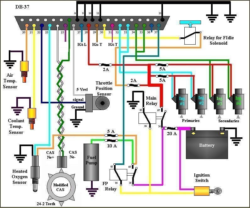 06-18-06, 06:21 AM
#22
Rotary Enthusiast
Thread Starter
I stopped in to visit Terrh this weekend. During cranking the left LED only should flicker, the other two should be on steady. That left LED is providing the trigger signal to the leading coilpack. His left LED was fickering during cranking, but he had to leading spark. We found leading and trailing trigger signals were reversed on his board, and swapped wires on his board as an easy fix as he had already terminated the other ends to his coil packs. Here's the updated wiring schematic, showing leading on 31, traiilng on 27.
Again, if a moderator could swap this image in to the first page of this thread, it would be greatly appreciated.
Again, if a moderator could swap this image in to the first page of this thread, it would be greatly appreciated.
02-28-07, 01:37 PM
#24
Senior Member

Join Date: May 2005
Location: MA
Posts: 283
Likes: 0
Received 0 Likes
on
0 Posts
I just wanted to add something useful to this.
If you plan on building this, buy an RS Autosport harness. Respectively the wiring is already there for you..
Wire S1 -> IGt-T (Bl/Y)
Wire S2 -> IGs-T (Br/Y)
Wire S3 -> IGt-L (R)
Wire S4 (e-fan? if you want)
T2GTUS provided me with this helpful information as well if you remove your stock harness:
For the trailing coil:
IGt-T = Bl/Y
IGs-T = Br/Y
TAC = Y/Bl ... I usually just run a line from this and T into the back of the gauge cluster which is also Y/Bl on the left plug.
leading coil:
IGt-L = R
all the Br need +12v switched ign. 1 Br on lead and 2 br on trailing(not sure why mazda separated the +12v on trailing)