4-Rotor FC Build
 12-10-14, 12:02 AM
#1851
Do you know how many scavange sections the MFR front cover has? I can see two scavange tubes in the pictures I've found, but can't see if there are one or two actual pump sections. I guess when going with an external setup that going for a 3-stage pump with 2 scavange sections makes sense.
The pressure is 18mm, and the two scavange is 14mm.
 12-10-14, 01:08 AM
#1852
The flow of oil would not take that route. A dry sump pump has 3 components: a collection tank, a scavenge section, and a pressure section.
The scavenge section picks up oil from the bottom of the engine.
The pressure section picks up oil from the tank.
John is asking about putting plumbing the oil cooler to the outlet of the scavenge pump, then flowing to the tank, or putting the cooler on the outlet of the pressure section.
The bubbles will not collect in the cooler; they remain entrained in the oil until they reach the swirl section of the vented tank. Fluids will follow the path of least resistance, and a bubble at the top of a row would certainly be a lower resistance path than a row fully filled with fluid.
The benefit of cooling on the scavenge side of the pump as opposed to the pressure side is that there is no pressure loss by pumping through the oil coolers, so for identical engine oil pressures, the power losses are less on this set-up. However, as John mentions, the air-entrained oil is less efficient at being cooled, and as such larger coolers are required (and higher pressure rated).
John seems less concerned about maximum power than an efficient, reliable oil cooling system. If his current coolers are adequate for pressure and heat capacity, I would plumb the pressure side in his scenario.
Wow, that's pretty small isn't it. Maybe the diameter of the pumping gears are a bit larger or something?
12-10-14, 01:25 AM
#1853
I have the info you want, just not on the phone.
12-10-14, 05:30 AM
#1854
Exhaust Manifold Leak
Yeah, I agree, it's not so bad. And that's for really nice CNC machined auto verdi ones. I found a few US based companies making less shiney ones out of extruded aluminium material, pricing for a 3-stage pump is about $6-700, They were spur gear type pumps though, so probably won't pull a huge amount of vacuum but that's not a major concern for me.
Do you know how many scavange sections the MFR front cover has? I can see two scavange tubes in the pictures I've found, but can't see if there are one or two actual pump sections. I guess when going with an external setup that going for a 3-stage pump with 2 scavange sections makes sense. How do you have the oil cooler plumbed by the way? Between pressure pump and engine? I've heard of people putting the cooler between the scavange sections and the pump. Downside being that there is still air mixed with the oil at that point, so a bigger cooler is needed. Upside is that there is little to no pressure on the cooler, and less pressure loss between the pressure pump and the engine because there isn't a cooler between them. I wonder if the cooler core I used for my radiator will be suitable for an oil cooler if it's plumbed between the scavange section and tank.
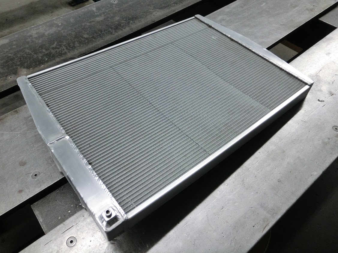
It's a 620x500x40 cooler core, to which I welded some tanks on. Maybe two of those stacked on top of each other with a big-fan on top of them will work nicely. The cores are about �175, so much more friendly on the pocket than a 50 or 60 row setrab cooler.
Ah well, just some thoughts. Lot's of stuff to consider, as usual.
Do you know how many scavange sections the MFR front cover has? I can see two scavange tubes in the pictures I've found, but can't see if there are one or two actual pump sections. I guess when going with an external setup that going for a 3-stage pump with 2 scavange sections makes sense. How do you have the oil cooler plumbed by the way? Between pressure pump and engine? I've heard of people putting the cooler between the scavange sections and the pump. Downside being that there is still air mixed with the oil at that point, so a bigger cooler is needed. Upside is that there is little to no pressure on the cooler, and less pressure loss between the pressure pump and the engine because there isn't a cooler between them. I wonder if the cooler core I used for my radiator will be suitable for an oil cooler if it's plumbed between the scavange section and tank.
It's a 620x500x40 cooler core, to which I welded some tanks on. Maybe two of those stacked on top of each other with a big-fan on top of them will work nicely. The cores are about �175, so much more friendly on the pocket than a 50 or 60 row setrab cooler.
Ah well, just some thoughts. Lot's of stuff to consider, as usual.
Spun the engine some times to 10k5-11k when miss shifting or loss of traction, engine doesnt seem to mind.
I think if the core is high flow/low pressure type, like for instance a water radiator core I think it should work if you put it in the return line to the tank. I would use -16 fittings for this as the scavenge sections, especially the lobe type, are not really made to create a lot of pressure in case of cold thick oil.
12-19-14, 05:04 PM
#1855
So a friend of mine bought a rallycar, and it came with a box with used parts. Within that box of used rally car parts were 3 dry sump pumps. So he let me take them apart to see if I could possibly use them for my 4-rotor.
Here are the pumps, they are 3-stage peterson pumps and use rotors instead of the often used spur gears.
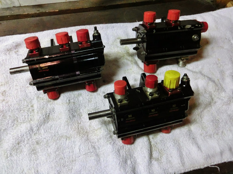
So this is a picture of the first pump opened up. It might look reasonably well on the picture, but one of the scavange rotors is cracked, and lot's of gauges an scratches on all the rotors are present. This pump definitely has seen an engine failure.

The other pumps however, look pretty good! Both have been used but only normal wear is visible on both. So, they look pretty usable, I'm just not entirely sure what the flow rate of these pumps are. The rotors are bigger and wider than the oem ones (67mm vs 50mm dia, 22.2 vs 17.5mm wide), but the oem pump does have another set of rotors stuffed behind the main ones. so it's hard to tell how the they compare in terms of flow. I tried getting flow numbers but no luck so far.
Here are the pumps, they are 3-stage peterson pumps and use rotors instead of the often used spur gears.
So this is a picture of the first pump opened up. It might look reasonably well on the picture, but one of the scavange rotors is cracked, and lot's of gauges an scratches on all the rotors are present. This pump definitely has seen an engine failure.
The other pumps however, look pretty good! Both have been used but only normal wear is visible on both. So, they look pretty usable, I'm just not entirely sure what the flow rate of these pumps are. The rotors are bigger and wider than the oem ones (67mm vs 50mm dia, 22.2 vs 17.5mm wide), but the oem pump does have another set of rotors stuffed behind the main ones. so it's hard to tell how the they compare in terms of flow. I tried getting flow numbers but no luck so far.
12-19-14, 10:07 PM
#1856
I went to the Peterson website, and their front page info section shows "Up to 30 GPM (113 LPM for you metric folks)" They do show rotor width measurements at 1.2" (30mm) on their 3-stage pump. the rotor they use is a 4 lobe, like yours above and they claim to use a rotor with a "twisted design". I'm not a fluid dynamics engineer, but if flow is a linear relation to rotor width, then 22.5mm/30mm=75%. So 75% flow would put it at 22.5 GPM or 85 LPM. Seems rather adequate, given the stock pump designs. Also, the stock pump still can put out over 100 psi and flow rather well for a 2 rotor.
12-21-14, 05:06 PM
#1857
I don't think the older and newer pumps can be directly compared by width if the rotors are a different design. It's probably easiest to setup a test rig, pumping oil from one canister into another with a known rpm for a known amount of time, and then work out how many litres are displaced. I think wider rotor sets and housings are still available, so worst case scenario I need to spend some money.
Anyway, my buddy let me use one of the spare pumps in exchange for some fabrication work, and my uncle gave me a few door-sized 10mm thick aluminium plates that have "dry sump plate" written all over them . So I sat down with the engine and all the newly acquired parts and thought about how to make everything work together.


The easiest method is to just make a mount for the pump, and stuff another pully in front of the current V-belt pully. However, that will interfere with the cooling ducting and radiator. I also don't like having a pully so far from the front bearing. So after considering multiple options I think I'm going to try and fit a timing belt pully between the triggerwheel and the front cover. There is not enough room there of course, but maybe I can machine down the front cover 20-25mm or so, cut out an aluminium plate that also has mounting points for the pump and just weld everything together. Doing that won't work with the current hub where the V-belt pully and triggerwheel mount onto so I found a billet piece of high carbon steel and made a new piece.

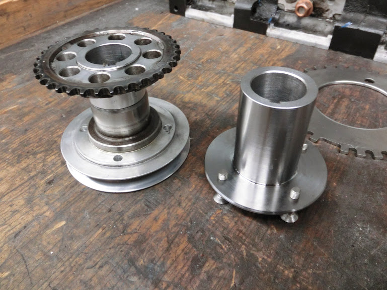

It's longer than the old piece, so the old oil pump drive gear and CAS drive gear can both be left out. The part where the crankshaft seal rides is longer, so I won't be having problems getting a seal and the timing belt drive gear can sit right up against the triggerwheel.
Next up is machining the aluminium cover down.
Anyway, my buddy let me use one of the spare pumps in exchange for some fabrication work, and my uncle gave me a few door-sized 10mm thick aluminium plates that have "dry sump plate" written all over them
The easiest method is to just make a mount for the pump, and stuff another pully in front of the current V-belt pully. However, that will interfere with the cooling ducting and radiator. I also don't like having a pully so far from the front bearing. So after considering multiple options I think I'm going to try and fit a timing belt pully between the triggerwheel and the front cover. There is not enough room there of course, but maybe I can machine down the front cover 20-25mm or so, cut out an aluminium plate that also has mounting points for the pump and just weld everything together. Doing that won't work with the current hub where the V-belt pully and triggerwheel mount onto so I found a billet piece of high carbon steel and made a new piece.
It's longer than the old piece, so the old oil pump drive gear and CAS drive gear can both be left out. The part where the crankshaft seal rides is longer, so I won't be having problems getting a seal and the timing belt drive gear can sit right up against the triggerwheel.
Next up is machining the aluminium cover down.
12-24-14, 05:25 PM
#1862
Exhaust Manifold Leak
12-25-14, 02:40 AM
#1863
Yes, on AutoVerdi I know, have two myself, but I meant John's pump on the picture. He should be able the switch side if he wants to. And also make a own bracket if he desides that, though it's "only" a plate.
12-25-14, 11:50 AM
#1864
Nope, not possible. The plates are assymetrical so it only fits one way.
No matter though, I won't use those for mounting, I'll probably mount the pump on the front using the 4 tension bolts. The pump will use a timing belt of course. Waterpump and alternator will use a V-belt.
No matter though, I won't use those for mounting, I'll probably mount the pump on the front using the 4 tension bolts. The pump will use a timing belt of course. Waterpump and alternator will use a V-belt.
12-28-14, 06:29 AM
#1865
Senior Member
Why use 2 belts? If you have to make new pulleys make them so you can use the timing belt you want. If the belt fails, all fail and you can shutoff the engine.
12-28-14, 11:21 AM
#1866
Exhaust Manifold Leak
Pump has not so strong bearings I think, Id be careful with putting too much load on it especially if it the alt is also driven by the same belt and on the pulling side of the belt before the alt.
12-28-14, 11:41 AM
#1867
What he said, There will be a lot of strain on that single belt, and it will pull very hard on the pump shaft and bearings. It's also difficult to get the right drive ratio. Only pullys with a reasonable diameter (90mm or so) will fit the waterpump, and it runs at about a 1:1 ratio with the crankshaft. Therefore the crankshaft main pully also needs to be about 90mm. The oil pump needs to run at about a 1:2 drive ratio, so when using one belt, the pully on the oilpump will be about 180mm, which is too big.
12-28-14, 11:53 AM
#1868
Exhaust Manifold Leak
What he said, There will be a lot of strain on that single belt, and it will pull very hard on the pump shaft and bearings. It's also difficult to get the right drive ratio. Only pullys with a reasonable diameter (90mm or so) will fit the waterpump, and it runs at about a 1:1 ratio with the crankshaft. Therefore the crankshaft main pully also needs to be about 90mm. The oil pump needs to run at about a 1:2 drive ratio, so when using one belt, the pully on the oilpump will be about 180mm, which is too big.
On our 13B PP water pump runs at 56% of crank and even at idle water is moving fast judging by the eye (no thermostat)
01-11-15, 02:31 PM
#1869
Right, I have to look at it some time, but I think my ratio is the same as stock. Maybe I should change it to the same ratio as the racingbeat underdrive pullys. I have a book with a chart with numbers somewhere I think.
Anyway, I got a reply from one of the peterson engineers, and he said these pumps put out 5GPM of flow for every 1000 pump rpm, and it increases equally with rpm, so 2000rpm is 10GPM ect. Now I did some searching, digging and asking around to find out how much flow I need, but it's not that easy because it depends on a lot of things like oil weight, bearing clearances and what sort of oil cooling jets are used but from what I found, I think this pump will work, but I am going to have to run it at about 60-65% of the crank speed instead of the usual 50%. This will cause the pump to run at 5000RPM, at the engine's redline of 8500RPM which is just about do-able. Now I just need to find the time to work on it, currently in istanbul for work for a few weeks so that's not helping.
Anyway, I got a reply from one of the peterson engineers, and he said these pumps put out 5GPM of flow for every 1000 pump rpm, and it increases equally with rpm, so 2000rpm is 10GPM ect. Now I did some searching, digging and asking around to find out how much flow I need, but it's not that easy because it depends on a lot of things like oil weight, bearing clearances and what sort of oil cooling jets are used but from what I found, I think this pump will work, but I am going to have to run it at about 60-65% of the crank speed instead of the usual 50%. This will cause the pump to run at 5000RPM, at the engine's redline of 8500RPM which is just about do-able. Now I just need to find the time to work on it, currently in istanbul for work for a few weeks so that's not helping.
01-19-15, 04:33 PM
#1870
John, can you please make more detailed pics of dissasembled peterson pump?
We are trying to build external oil pump by using stock rx7 oil pump components, just machining new housings and longer shafts...
Only thing we are not sure about is how is external oil pump sealed on the shaft and how/if connect passages between rotors in case we would put together 4 rotor sets instead of stock 2 rotors (basically 2 FD/FD oil pumps together)
Thanks
01-20-15, 03:58 AM
#1871
Exhaust Manifold Leak
basicly you can leave the passages closed between the sets as long as each set has has 1 side open it will work.
the more optimal way to do this whoud be to make between each set a plate that is open and has a connection to a manifold. so lets say on top you have 5 passages in total which exits in 5 fittings or maybe a manifold or cavity. 3 are from the plates in between the sets and 2 will be from the end plates. I hope you and vizualize what I mean..
the more optimal way to do this whoud be to make between each set a plate that is open and has a connection to a manifold. so lets say on top you have 5 passages in total which exits in 5 fittings or maybe a manifold or cavity. 3 are from the plates in between the sets and 2 will be from the end plates. I hope you and vizualize what I mean..
01-20-15, 02:47 PM
#1872
Sure thing higgi, here you go:

Each section is sealed, there is an o-ring in the outer aluminium housing that seals the outside, the shafts are also sealed by an o-ring that fits in the dividing plates


That last picture also shows how itś possible to have multiple suction fittings to a pump and only one fitting for the scavange oil output. Each scavange rotor set has each own suction fitting and oil line to the engine, which is why the bottom parts are always closed. The top (output) part is machined open, and there is also an opening in the dividing plate between the 2 suction rotor sets. Because of this only one scavange oil output fitting is needed, so you don need multiple oil lines between the pump and the tank, or an external manifold.

Thatś the outer plate which holds a pressure relief valve. Very simple, just a plunger, a spring, and a bolt.

This picture compares the 2 rotor sets found in one stock FD pump, with one rotor set found in the peterson dry sump pump. With a little measuring and guessing I think the peterson one has a bit more capacity than the 2 FD rotors combined, but the difference isn�t major. The FD rotors aren't really small, they just can�t work very efficiently because one is fitted behind the other one in the oem pump, and the pumped oil has a lot of air in it. When using these for a dry sump system for a 2 or 3 rotor I think 2 of these rotor sets will do for a pressure pump. For a 4-rotor I would go with 3 rotor sets. Note that with a dry sump pump the scavange section is usually twice as big as the pumping section. So for a 2-rotor you will end up with a total of 6 rotor sets and for a 4-rotor you will probably end up with 9 rotor sets. Also note that this is a 50mm FD pump, the older 13B�s have smaller rotor sets.
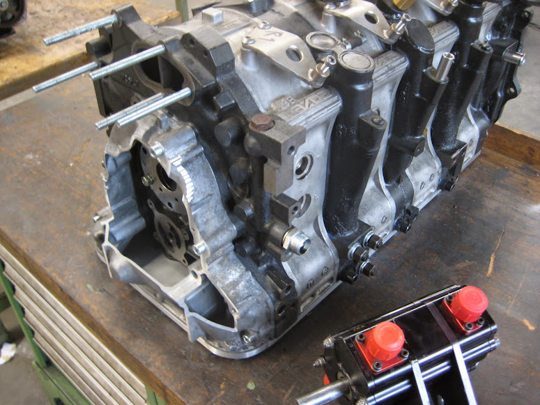
Back to my own project, I returned to the netherlands, and started with mocking up a front iron with the e-shaft and pully stuff:

After that I machined a junk housing, to see if my idea would work:


Maybe the above pictures will explain what I�m planning a bit better. The idea is to cut a 6-8mm or so aluminium plate, and weld that to the machined front cover. Special care will need to be taken during welding to minimize the warping as much as possible, and after welding I will machine the sealing surfaces flat again. I will also have to machine the hole for the front seal again, but when that�s done I should have enough room between the triggerwheel and the front cover to mount an oil pump drive gear in between there. After that I will start fabricating an oil pump mount and an alternator mount but that will come later. Doing this is a bit more work, but having all the pullys as close to the front bearing as possible will relieve a lot of strain from the front bearing and the e-shaft. Hopefully more progress and pictures will follow next weekend.
Each section is sealed, there is an o-ring in the outer aluminium housing that seals the outside, the shafts are also sealed by an o-ring that fits in the dividing plates
That last picture also shows how itś possible to have multiple suction fittings to a pump and only one fitting for the scavange oil output. Each scavange rotor set has each own suction fitting and oil line to the engine, which is why the bottom parts are always closed. The top (output) part is machined open, and there is also an opening in the dividing plate between the 2 suction rotor sets. Because of this only one scavange oil output fitting is needed, so you don need multiple oil lines between the pump and the tank, or an external manifold.
Thatś the outer plate which holds a pressure relief valve. Very simple, just a plunger, a spring, and a bolt.
This picture compares the 2 rotor sets found in one stock FD pump, with one rotor set found in the peterson dry sump pump. With a little measuring and guessing I think the peterson one has a bit more capacity than the 2 FD rotors combined, but the difference isn�t major. The FD rotors aren't really small, they just can�t work very efficiently because one is fitted behind the other one in the oem pump, and the pumped oil has a lot of air in it. When using these for a dry sump system for a 2 or 3 rotor I think 2 of these rotor sets will do for a pressure pump. For a 4-rotor I would go with 3 rotor sets. Note that with a dry sump pump the scavange section is usually twice as big as the pumping section. So for a 2-rotor you will end up with a total of 6 rotor sets and for a 4-rotor you will probably end up with 9 rotor sets. Also note that this is a 50mm FD pump, the older 13B�s have smaller rotor sets.
Back to my own project, I returned to the netherlands, and started with mocking up a front iron with the e-shaft and pully stuff:
After that I machined a junk housing, to see if my idea would work:
Maybe the above pictures will explain what I�m planning a bit better. The idea is to cut a 6-8mm or so aluminium plate, and weld that to the machined front cover. Special care will need to be taken during welding to minimize the warping as much as possible, and after welding I will machine the sealing surfaces flat again. I will also have to machine the hole for the front seal again, but when that�s done I should have enough room between the triggerwheel and the front cover to mount an oil pump drive gear in between there. After that I will start fabricating an oil pump mount and an alternator mount but that will come later. Doing this is a bit more work, but having all the pullys as close to the front bearing as possible will relieve a lot of strain from the front bearing and the e-shaft. Hopefully more progress and pictures will follow next weekend.

 02-01-15, 10:21 AM
#1874
Made a sump plate:

Not sure yet how I'm going to do the suction tubes, but I'm thinking something like this:
https://www.rx7club.com/attachments/...oto003_002.jpg
Started with modifying the front cover, need to do some welding now:
Not sure yet how I'm going to do the suction tubes, but I'm thinking something like this:
https://www.rx7club.com/attachments/...oto003_002.jpg
Started with modifying the front cover, need to do some welding now:
02-02-15, 01:19 PM
#1875
Senior Member

Looks great.
But i'm wondering, don't you need a lower point so the oil flow's somewhere like towards a place where it gets sucked up?
I mean, first thing that come's up to my head is the same what happens if you move a pan around bit just a bit of water. It can go anywere. So in your case, the oil can move away from the "suction cup" if you would like to call it that.
I can imagine that the pump doesn't like it when it does not get oil.