SCCA Super Touring U Build
 03-28-12, 09:28 PM
#1
SCCA Super Touring U Build
Since Fall 2009 I have been in the process of converting my 83 Improved Touring 7 RX7 to one of the SCCA's newest classes. I'm not done yet but have reached a point where the light at the end of the tunnel is a little brighter. So, I thought I would share the experience with you.
The Super Touring category is relatively new to the SCCA. It was originally introduced in 2006 as a set of National classes that would allow ex-SCCA Pro Racing World Challenge cars a place to compete in SCCA Club Racing. In the beginning two classes were called B Prepared and D Prepared. The BP class for Vettes, Vipers, etc and DP for the small bore sedans. In 2008 the classes were renamed Super Touring Over (over 3.0L) and Super Touring Under (under 3.0L). In addtion to the rename the SCCA decided to allow 1989 and later SCCAvImproved Touring cars to compete in STU as a way to boost the class and let more drivers experience SCCA National Racing. In 2009 the age rule changed to 1985 which made my car eligible because it was series produced through calendar year 1985.
The make up of the Super Touring class also changed from being a haven for ex-pro cars to being a builder's class. As a result the rules have been written, rewritten and then changed again. This has posed a number of challenges over the years and I suspect dealing with this rule set will continue to be "fun" for years to come. At least the SCCA has been responsive to some of my rules requests.
At it's heart Super Touring is an engine swap class. Eligible cars are allowed to use any engine as long as it was available in the US, from 1985 to present, and is available from the maker of the car. So this means my RX7 can use any Mazda engine that was sold in the US since 1985. This would include rotory and pistion engines both normally aspirated and turbocharged. In STU the engine displacement limit for my car is a 3.2L V6.
The cars in the class are balanced by a wieght x engine displacement formula of 1.1lbs per CC. Turbocharged cars use a weight scale that factors in a Single Inlet Restriictor (SIR). Currently normally aspirated rotaries are allowed at favorable wieghts - 2200 for a Street Port 12A and 2300 for a Street Port 13B. Renesis engines are allowed at 2300 (unported) and jsut this month a Bridge Ported 13B was classed at 2600lbs. Induciton is limited to stock EFI or a 2bbl Weber with specific chokes.
You can read more at www.SCCA.com - Club Racing - Cars and Rules.
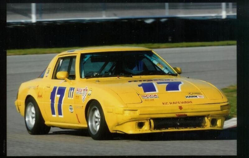
Here is the starting point - built in 1995 as an ITA racecar. I am the car's 4th owner and I bought it in 2003. Over the next 7 seasons I won 16 clubraces, 1 SCCA Pro Race, set 3 track records and shared a Division points championship in 2007:
From an October race at Gateway International 2008

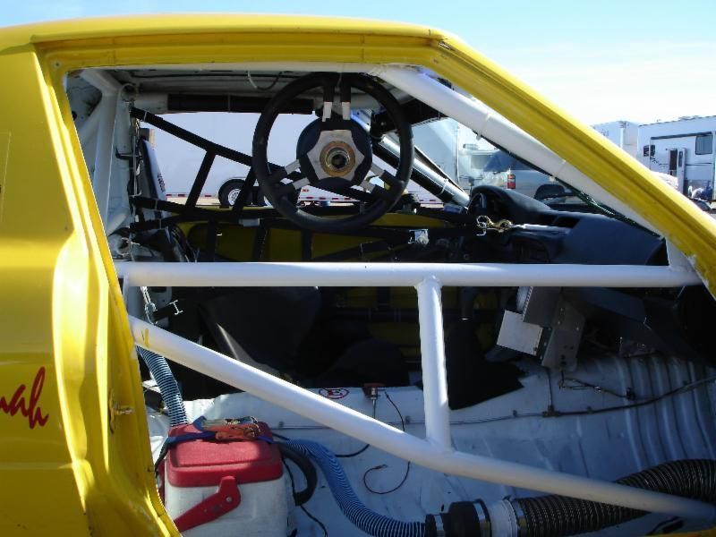
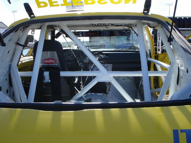
The interior

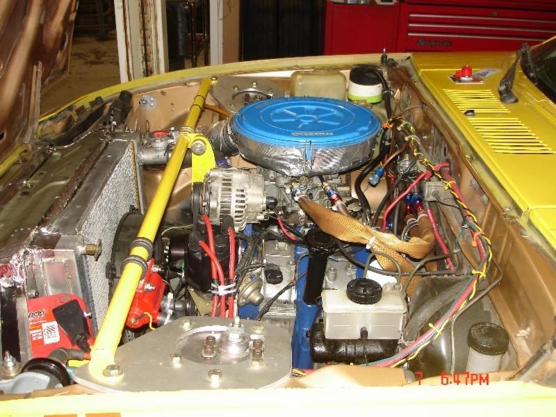
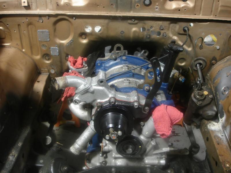
The engine - 12A Stock Port with an ISC Niki and ISC Header

The Super Touring category is relatively new to the SCCA. It was originally introduced in 2006 as a set of National classes that would allow ex-SCCA Pro Racing World Challenge cars a place to compete in SCCA Club Racing. In the beginning two classes were called B Prepared and D Prepared. The BP class for Vettes, Vipers, etc and DP for the small bore sedans. In 2008 the classes were renamed Super Touring Over (over 3.0L) and Super Touring Under (under 3.0L). In addtion to the rename the SCCA decided to allow 1989 and later SCCAvImproved Touring cars to compete in STU as a way to boost the class and let more drivers experience SCCA National Racing. In 2009 the age rule changed to 1985 which made my car eligible because it was series produced through calendar year 1985.
The make up of the Super Touring class also changed from being a haven for ex-pro cars to being a builder's class. As a result the rules have been written, rewritten and then changed again. This has posed a number of challenges over the years and I suspect dealing with this rule set will continue to be "fun" for years to come. At least the SCCA has been responsive to some of my rules requests.
At it's heart Super Touring is an engine swap class. Eligible cars are allowed to use any engine as long as it was available in the US, from 1985 to present, and is available from the maker of the car. So this means my RX7 can use any Mazda engine that was sold in the US since 1985. This would include rotory and pistion engines both normally aspirated and turbocharged. In STU the engine displacement limit for my car is a 3.2L V6.
The cars in the class are balanced by a wieght x engine displacement formula of 1.1lbs per CC. Turbocharged cars use a weight scale that factors in a Single Inlet Restriictor (SIR). Currently normally aspirated rotaries are allowed at favorable wieghts - 2200 for a Street Port 12A and 2300 for a Street Port 13B. Renesis engines are allowed at 2300 (unported) and jsut this month a Bridge Ported 13B was classed at 2600lbs. Induciton is limited to stock EFI or a 2bbl Weber with specific chokes.
You can read more at www.SCCA.com - Club Racing - Cars and Rules.
Here is the starting point - built in 1995 as an ITA racecar. I am the car's 4th owner and I bought it in 2003. Over the next 7 seasons I won 16 clubraces, 1 SCCA Pro Race, set 3 track records and shared a Division points championship in 2007:
From an October race at Gateway International 2008

The interior


The engine - 12A Stock Port with an ISC Niki and ISC Header

Last edited by mustanghammer; 02-26-15 at 10:18 PM. Reason: put pictures back in
 03-28-12, 09:40 PM
#2
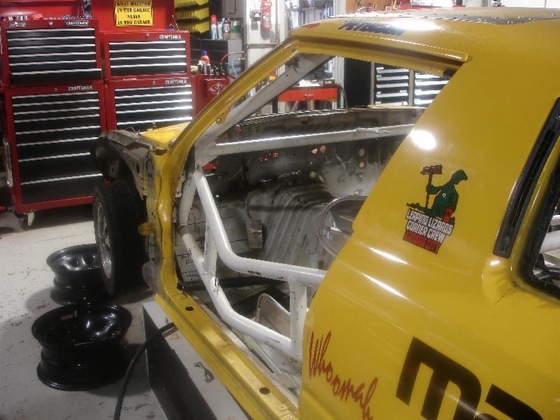
Frist steps - stripping the car.
Interior getting stripped as well. Factory steering column mounts cut out of the car and the brake/clutch pedal assembly has been removed.
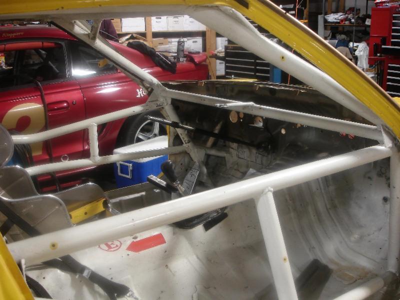
Another shot of the interior - the steering shaft can be seen
The 12A engine shortly before removal
Interior getting stripped as well. Factory steering column mounts cut out of the car and the brake/clutch pedal assembly has been removed.

Another shot of the interior - the steering shaft can be seen

The 12A engine shortly before removal

Last edited by mustanghammer; 02-26-15 at 10:29 PM. Reason: replace pictures
 03-28-12, 09:57 PM
#4
Roll Cage and Chassis work
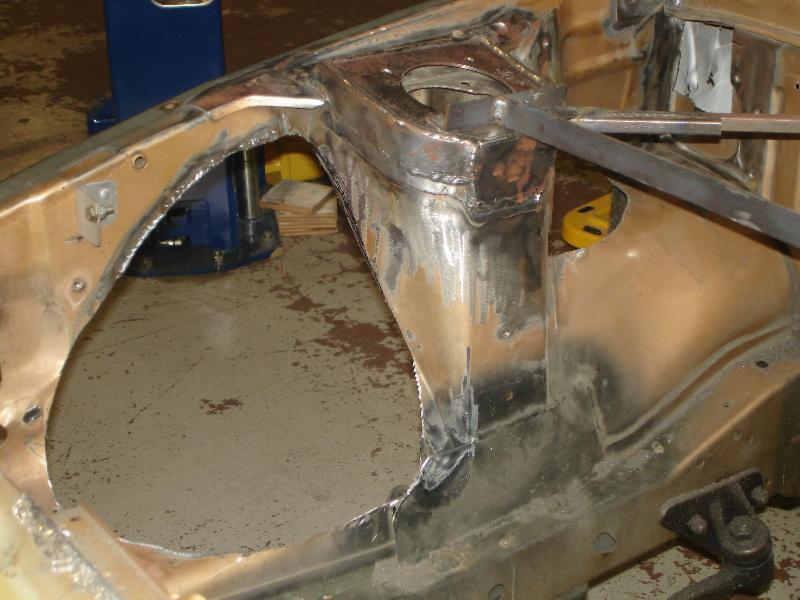
The STO/STU rule sets allow for inner fender modificatons. Since fender flares are not allowed and an 8" wide wheel is i decided to do some cutting in the engine compartment. This will allow the car to be lowered drastically without tire rub issues. Before cutting out the inner fenders I made a temporary brace so that the shock towers would not move. You can see this in some of the photos
Left front inner fender removed - this includes cutting into the box structure that runs across the top on both sides.
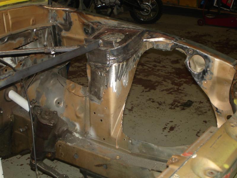
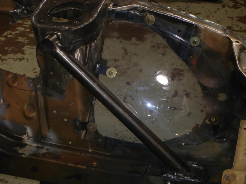
Right Wheel Well
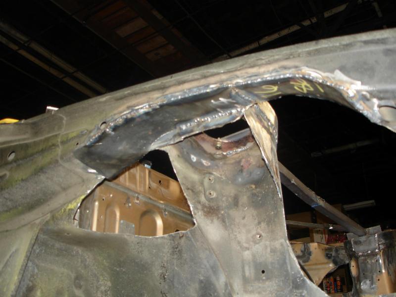
The openning in the boxed section was sealed with 16ga-14ga steel to maintain strength. This work was done on both sides
New inner fenders were made out of basement window covers from Lowes. There is some additional cage work in some of these phots that I will detail later
The STO/STU rule sets allow for inner fender modificatons. Since fender flares are not allowed and an 8" wide wheel is i decided to do some cutting in the engine compartment. This will allow the car to be lowered drastically without tire rub issues. Before cutting out the inner fenders I made a temporary brace so that the shock towers would not move. You can see this in some of the photos
Left front inner fender removed - this includes cutting into the box structure that runs across the top on both sides.

Right Wheel Well

The openning in the boxed section was sealed with 16ga-14ga steel to maintain strength. This work was done on both sides

New inner fenders were made out of basement window covers from Lowes. There is some additional cage work in some of these phots that I will detail later

Last edited by mustanghammer; 02-26-15 at 10:36 PM. Reason: Adding photos back
03-28-12, 10:14 PM
#6
More Cage work
Mounting the forward tubes in the rollcage. These tubes are required for SCCA Production and GT cars. They are also allowed in Super Touring. Connecting the front of an RX7 to the roll cage makes a HUGE difference in how these cars handle. The front of this car will be triangulated and connected to the rest of the car through the cage.
On the left side. This is a 14ga plate that replaced the OE firewall on that side. The tube that passes through it will be welded to the plate as well as to the shock tower and the cage inside the car. Attaching the tube to the firewall adds to its effectivness.
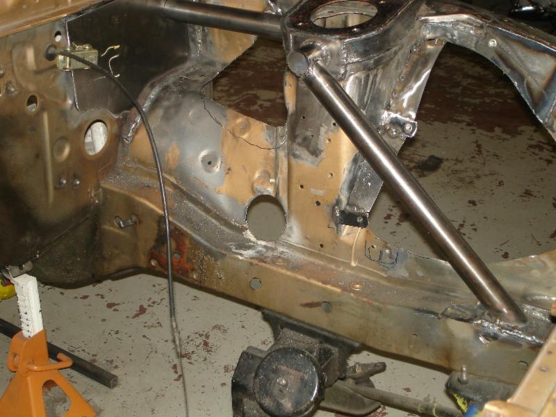
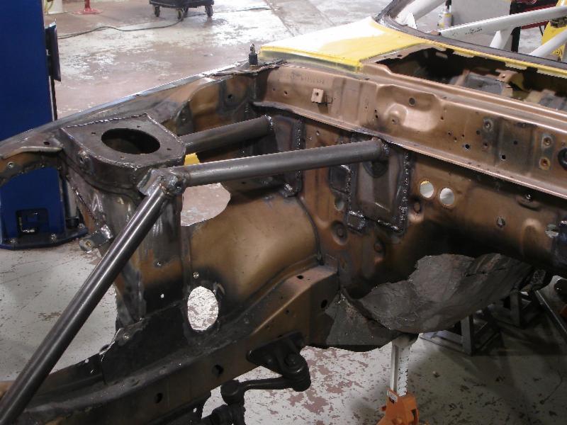
Two more tubes are added to create the triangle. These tubes do not pass through the firewall. Instead they weld to the 11ga plates that have separate tubes on the inside of the car that attach to the cage.
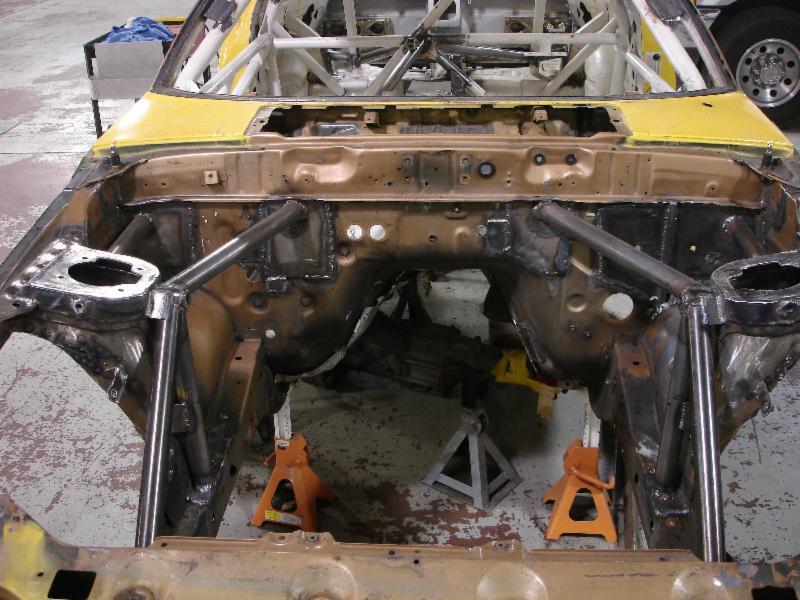
Inside the car - the two center tubes can be seen
Left side detail

Mounting the forward tubes in the rollcage. These tubes are required for SCCA Production and GT cars. They are also allowed in Super Touring. Connecting the front of an RX7 to the roll cage makes a HUGE difference in how these cars handle. The front of this car will be triangulated and connected to the rest of the car through the cage.
On the left side. This is a 14ga plate that replaced the OE firewall on that side. The tube that passes through it will be welded to the plate as well as to the shock tower and the cage inside the car. Attaching the tube to the firewall adds to its effectivness.


Two more tubes are added to create the triangle. These tubes do not pass through the firewall. Instead they weld to the 11ga plates that have separate tubes on the inside of the car that attach to the cage.

Inside the car - the two center tubes can be seen

Left side detail


Trending Topics
03-31-12, 07:34 PM
#9
The rest of the cage upgrades
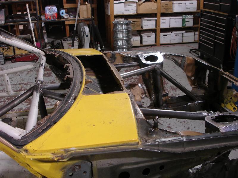
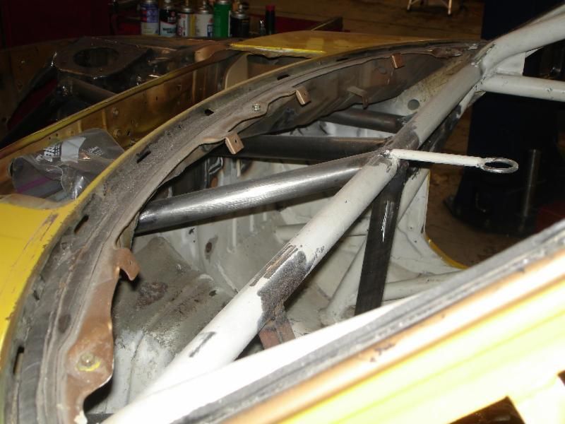
At the back of the car I triangulated the area between the spring mounts and the center of the main hoop. This car has to use the OE rear spring location so I extended the cage to the factory reinforcement structures.
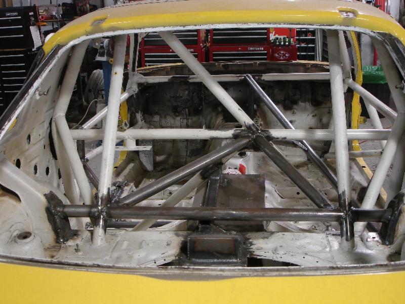
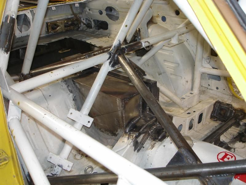
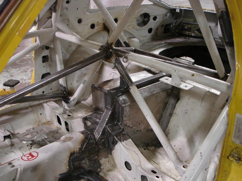
In the center I used an "X" brace to connect the front and rear of the car. An alternate option would have been a single straight tube from the front to the back but this places a tube close to the driver. The "X" brace moves the tubing away from me and distributes loads to multiple locations in the cage.
Rear
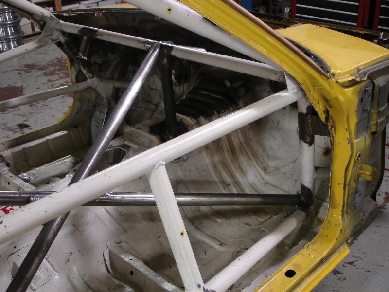
Front
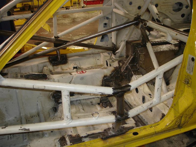
On the driver's side I added another tube to the door bars and then attached the door bars to the rocker sill. The bace to the rocker sill sets on top of a jack post the goes through the rocker panel. I did the same thing on the passenger side.
At the back of the car I triangulated the area between the spring mounts and the center of the main hoop. This car has to use the OE rear spring location so I extended the cage to the factory reinforcement structures.

In the center I used an "X" brace to connect the front and rear of the car. An alternate option would have been a single straight tube from the front to the back but this places a tube close to the driver. The "X" brace moves the tubing away from me and distributes loads to multiple locations in the cage.
Rear

Front

On the driver's side I added another tube to the door bars and then attached the door bars to the rocker sill. The bace to the rocker sill sets on top of a jack post the goes through the rocker panel. I did the same thing on the passenger side.
 04-01-12, 08:19 PM
#10
I started by making tops out of 11ga steel. The strut hole was cut with a 3" hole saw on a Mill/Drill. The strut mount holes were copied from the oe mounting holes. So that the new strut tops would be in correct place I bolted the new tops to the OE strut tops. I used some double ended lug nuts for spacers so that the new top is about an inch higher. I also angled the new strut tops by spacing the forward holes more than the rear holes to help the upper spherical strut bearing align better in its race.
New strut tops bolted into place with the front and back side tacked in place

The sides were formed out of 11ga steel and welded/hammered into shape

The OE strut tops were cut out with a plasma cutter at a later date.
Right side finished
[
 04-02-12, 05:27 PM
#11
rear
I did similar on the rear. I'm definitely going to copy what you did for the front. Mine won't sit quite as low as yours for everyday use. I'm looking for a little more suspension travel for the street but I do want to be able to set it pretty low for autocross. Here is what I did on the rear. This should give me enough shock travel.
04-03-12, 11:12 PM
#12
I did similar on the rear. I'm definitely going to copy what you did for the front. Mine won't sit quite as low as yours for everyday use. I'm looking for a little more suspension travel for the street but I do want to be able to set it pretty low for autocross. Here is what I did on the rear. This should give me enough shock travel.
To get shock travel on my car I lowered the shock mounts on the rear axle. Either way you do it, this is a good mod because allot of shock travel is lost when you lower these cars.
04-10-12, 11:32 PM
#13
Suspension
Long before I started updating the roll cage for this project, I started working on the rear suspension. This was not completely planned as I had originally intended to do the cage first but the cage allowances for Super Touring were not clear in the fall of 2009. So I worked on what I could. The joys of building a car to a half baked rule set, I guess.
I investigated several designs before settling on a three link. One of the first considerations was a modified 4 link like the one used successfully in E Production. I decided against this design because it used up too much rear wheel well room. In hind sight this design could have been used because inner wheel wells were eventually opened up for modification in the Super Touring rule set.
Here is a modified 4 link from my friends E Production car. By the way this car won the 2011 E Production SCCA National Championship.
The upper arm mounts to a bracket that is part of the cage. This setup works but drivers report some bind related issues.
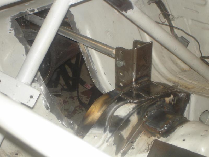
Here is what I decided to go with - 3 Link with a Pan Hard bar. The third link has 7 adjustment holes to accommodate a number of ride height and geometry changes.
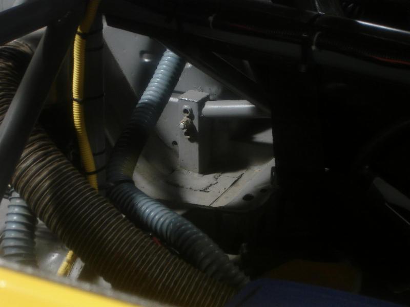
Here is the 3rd link covered. The top and sides was constructed our of one piece of 18ga steel. The front was 16 ga steel with 14-11ga reinforcements. This piece took a real long time to make and attach to the car. I sealed it with automotive seam sealer. This needs to provide a fire barrier
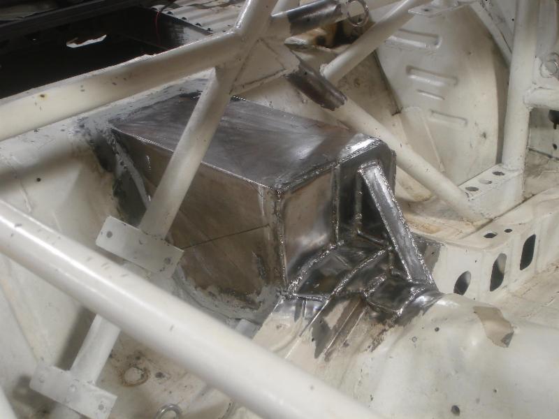
Later I braced the the third link mount to the cage. This mount will apply allot of force to the car and if it can flex it will eventually fail. Been there - seen that.
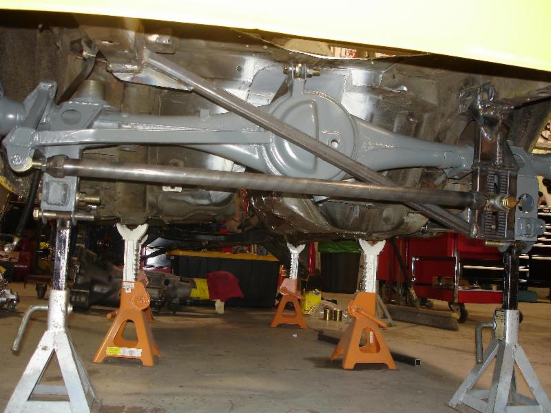
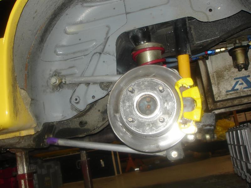
Here is the view of the suspension from under the car

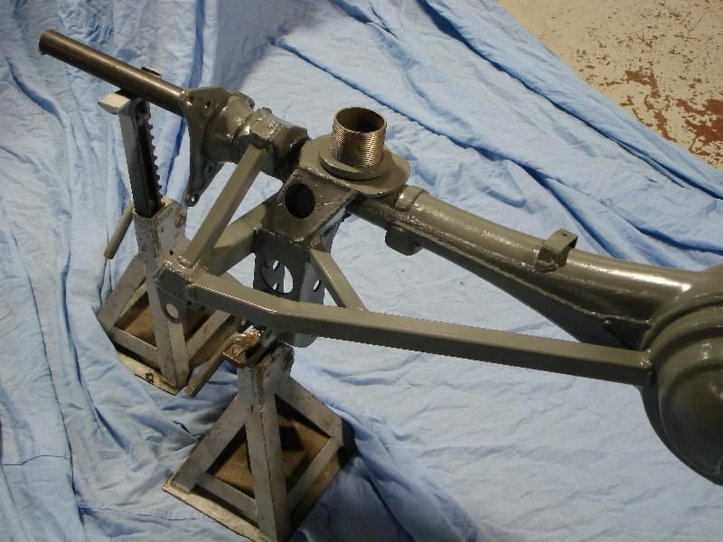
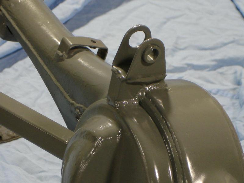
Rear axle housing. Panhard mount, third link mount and lower control arm mounts
I investigated several designs before settling on a three link. One of the first considerations was a modified 4 link like the one used successfully in E Production. I decided against this design because it used up too much rear wheel well room. In hind sight this design could have been used because inner wheel wells were eventually opened up for modification in the Super Touring rule set.
Here is a modified 4 link from my friends E Production car. By the way this car won the 2011 E Production SCCA National Championship.


The upper arm mounts to a bracket that is part of the cage. This setup works but drivers report some bind related issues.
Here is what I decided to go with - 3 Link with a Pan Hard bar. The third link has 7 adjustment holes to accommodate a number of ride height and geometry changes.

Here is the 3rd link covered. The top and sides was constructed our of one piece of 18ga steel. The front was 16 ga steel with 14-11ga reinforcements. This piece took a real long time to make and attach to the car. I sealed it with automotive seam sealer. This needs to provide a fire barrier

Later I braced the the third link mount to the cage. This mount will apply allot of force to the car and if it can flex it will eventually fail. Been there - seen that.


Here is the view of the suspension from under the car
Rear axle housing. Panhard mount, third link mount and lower control arm mounts


 04-11-12, 02:34 PM
#17
3 link
I was looking at the 3 link setup. Question, is there a reason you ditched the watts linkage? Would it be in the way? I was thinking about using it with a 3 link setup.
Really digging the work! To me the fab work is the best part of doing a car.
Really digging the work! To me the fab work is the best part of doing a car.
04-11-12, 08:42 PM
#18
[
 04-11-12, 08:54 PM
#19
The OE watts link is mounted too high in the car and yes, the arms would interfere with the third link. If you want to use a watts link it would need to mount to the back of the rear end housing.
An alternative would be to build a watts link that pivots on the chassis with arms that attach to the rear axle. To see this design go to http://fays2.net and check out the watts link they make for Mustangs.
I went with a panhard bar for several reasons. First it is cheaper - there are only 2 heims. It is lighter because it is simple. Finally, it is possible to get a lower roll center with a panhard rod.
A watts link is a better design because it imparts no handling vices as the car goes through roll. That said, a panhard bar works and is butt simple.
04-12-12, 11:33 PM
#21
The problem that I see with the Mazda rear axle housing is that axle clamps won't work because the axle tubes have an irregular shape. This means that brackets would have to be welded to the tubes which presents some challenges. The other issue would be exhaust clearance.
That said, the Fays2 system is something I may put on my Fox Mustang at some point in the future.
04-21-12, 10:55 PM
#22
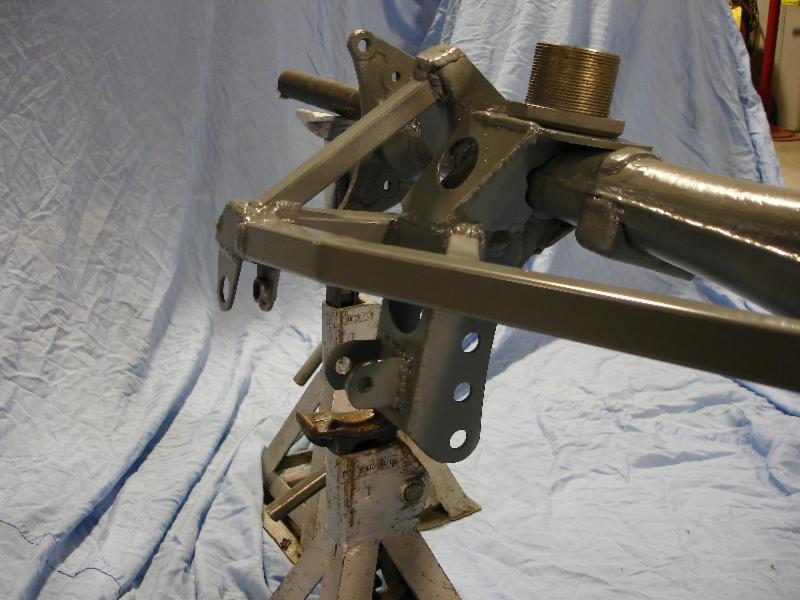
Bump Steer Correction
I decided to build in the ability to correct bumpsteer in the front suspension. I have been racing the car for 7 years with a 1" strut spacer and the car lowered probably 2" below stock and I really haven't noticed in bumpsteer. That said it is probably an issue.
Bumpsteer will be corrected at the spindle by using a rod end to replace the outer tie rod end. Typically a 14MM female rod end is used but I decided to use a 5/8 rod end because it will allow me to use spacers that are left over from the bumpsteer kit I put on my Mustang. This meant that I have to build an adjusting stud that has 14mm Right Hand thread on one end and 5/8 Left hand thread on the other. Here is how I did it.
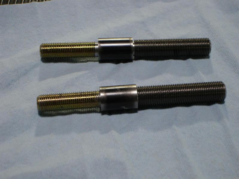
Starting with a new adjusting stud I cut off the RH end and turned it down to 1/2 on a lathe. For the 5/8 side I purchased a 12" hardened steel threaded rod from McMaster-Car and cut it to length. I also turned one end to 1/2 on the lathe. To join the two haves I cut 1" length of 1/2 inside diameter tubing. Everthing was TIG welded together by my friend David Long
Pictures
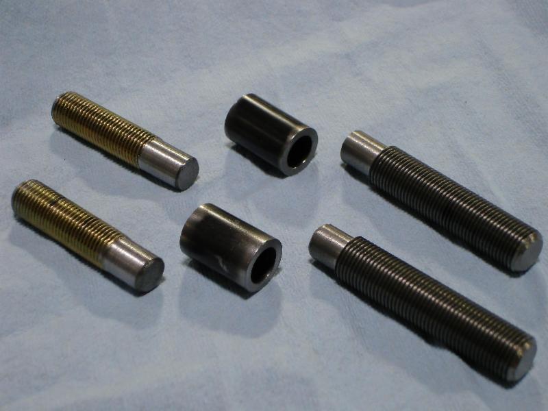
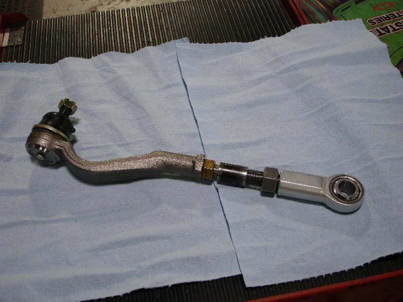
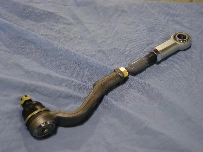
Bumpsteer will be corrected at the spindle by using a rod end to replace the outer tie rod end. Typically a 14MM female rod end is used but I decided to use a 5/8 rod end because it will allow me to use spacers that are left over from the bumpsteer kit I put on my Mustang. This meant that I have to build an adjusting stud that has 14mm Right Hand thread on one end and 5/8 Left hand thread on the other. Here is how I did it.
Starting with a new adjusting stud I cut off the RH end and turned it down to 1/2 on a lathe. For the 5/8 side I purchased a 12" hardened steel threaded rod from McMaster-Car and cut it to length. I also turned one end to 1/2 on the lathe. To join the two haves I cut 1" length of 1/2 inside diameter tubing. Everthing was TIG welded together by my friend David Long
Pictures


 04-21-12, 11:16 PM
#23
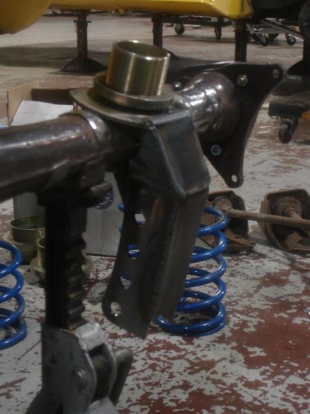
More Bumpsteer
One of the issues with using a rod end in place of a standard tie rod end is that a rod end will not allow as much misalignment. This particularly an issue when the suspension is in droop. What happens is that the ball in the rod end binds against its race. Eventually this can damage the rod end. To help resolve this I heated and twisted the steering knuckle a few degrees.
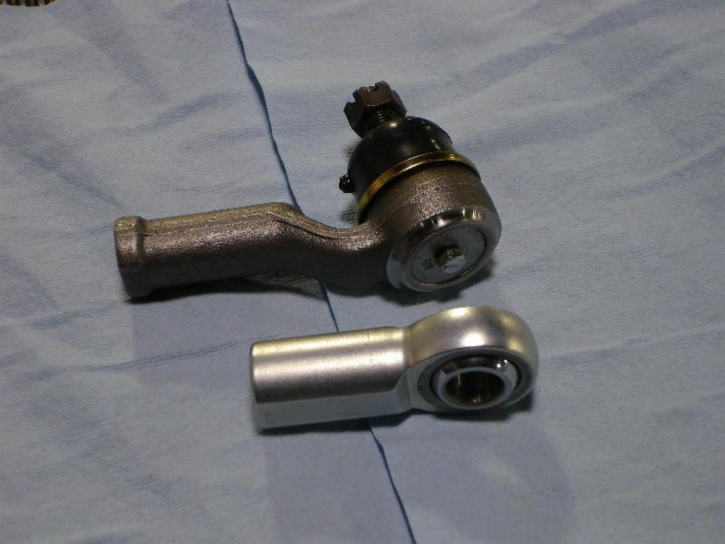
Here is the difference between an OE tie rod end and the 5/8" rod ends I am using
Right Hand Knuckle - Before
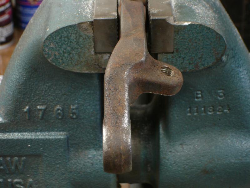
Right Hand Knuckle - After
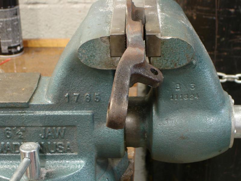
Note, this is the second set of steering knuckles I did this too. The first set were bent the wrong way!
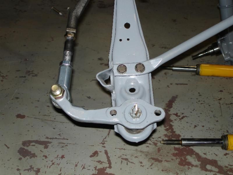
Before putting a twist in the steering knuckle, I drilled steering arm to 5/8". I also drilled the strut mounts out to 1/2"
Installed!
Here is the difference between an OE tie rod end and the 5/8" rod ends I am using

Right Hand Knuckle - Before

Right Hand Knuckle - After

Note, this is the second set of steering knuckles I did this too. The first set were bent the wrong way!
Before putting a twist in the steering knuckle, I drilled steering arm to 5/8". I also drilled the strut mounts out to 1/2"
Installed!
 04-24-12, 09:11 PM
#25
Thanks
The OE watts link is mounted too high in the car and yes, the arms would interfere with the third link. If you want to use a watts link it would need to mount to the back of the rear end housing.
An alternative would be to build a watts link that pivots on the chassis with arms that attach to the rear axle. To see this design go to http://fays2.net and check out the watts link they make for Mustangs.
I went with a panhard bar for several reasons. First it is cheaper - there are only 2 heims. It is lighter because it is simple. Finally, it is possible to get a lower roll center with a panhard rod.
A watts link is a better design because it imparts no handling vices as the car goes through roll. That said, a panhard bar works and is butt simple.
Regarding lateral axle location -- have you considered a horizontally mounted watts link attached to the bottom of the pumpkin? It seems to provide a low roll center, and it moves the mechanism away from the back of the axle, where I'm lacking in real estate.