SPAL FAN-PWN install e-fan controller
 05-12-08, 03:08 PM
#26
Lives on the Forum

No, if you're connecting to a single wire temp sensor, use the white wire and ignore the twin wire plug.
The pic is confusing since it shows a double wire sensor, but your single wire sensor grounds through the sensor body.
-Ted
The pic is confusing since it shows a double wire sensor, but your single wire sensor grounds through the sensor body.
-Ted
 05-12-08, 03:25 PM
#27
Engine, Not Motor
iTrader: (1)
Join Date: Feb 2001
Location: London, Ontario, Canada
Posts: 29,789
Likes: 0
Received 108 Likes
on
91 Posts
I want to get rid of the stock clutch fan and this seems better than just switching the fan at one temperature from my Power FC.
Ok I am reading through the instructions on how to wire this thing up:
http://www.spalusa.com/fans/automate...ts/FAN-PWM.pdf
I am looking at page 5 of the document (pdf page 4), single fan SPAL sensor w/o A/C, which is what I would run (except the sensor would be my autometer wire). There are 4 grounds listed:
http://www.spalusa.com/fans/automate...ts/FAN-PWM.pdf
I am looking at page 5 of the document (pdf page 4), single fan SPAL sensor w/o A/C, which is what I would run (except the sensor would be my autometer wire). There are 4 grounds listed:
1. Large gauge black: battery ground. I would probably just wire this to chassis because I relocated the battery. Shouldn't matter should it?
Good news though: I spoke to a Spal engineer and shared my concerns regarding the circuit. He agreed and mentioned that indeed they have already changed this for the next version! There is now a separate signal ground and power ground. This should go a long way to eliminating ground issues.
2. Primary fan black: that's just the ground for the fan itself, I'd probably ground it with the other large gauge black wire. I presume this thing doesn't require any other relays?
3. Temp sensor black, small gauge: Is this the one that is sensitive to length? Since I will be using a 1-wire sender, I guess it doesn't matter.
4. White wire, small gauge: this is another ground presumably for the control system itself. Once again, I am unclear which wire was giving you trouble. I was going to ground this to a separate location from the the large gauge ground wires.
My hookup is as follows:
Black on 3 conductor Weatherpack: Cut. Now grounded to chassis directly from unit.
Red on 3 conductor Weatherpack: 12V constant fused (30A).
Orange on 3 conductor Weatherpack: IGN 12V
White on temp harness: ECU side of OEM ECT (purple wire on my Microtech, not sure what colour on stock harness)
Red and black fan wires: to + and - on fan.
The 3 conductor triangle plug temperature harness comes in two variations in my version of the product. Two harnesses are included: one for OEM sensors and one for Spal sensors. The Spal sensor appears to be GM style ECT. I don't use this. So you will use one harness and file the other away for safe keeping in case you change later.
Any input? Also, what fan are you using this with? Is it a single fan, dual fan, single speed, dual speed?
I am trying to figure my whole e-fan setup so I can just do it correctly the first time. I currently have a T04S turbo with the HKS log manifold and custom TID (just a 90 degree elbow coming off the inlet) that required me to cut the stock fan shroud in the corner. It looks awful, and I've been meaning to get rid of it when I can work out a truly solid e-fan setup that will cool reliably and not have clearance issues.
 ). It will pull BIG current though so if you control it only with a relay, you need a 40A unit.
07-15-08, 10:38 AM
). It will pull BIG current though so if you control it only with a relay, you need a 40A unit.
07-15-08, 10:38 AM
#29
http://cgi.ebay.com/ebaymotors/Parts...3286.m20.l1116
is this the correct cooling fan? It looks like it. I am going to do the e-fan conversion in the next couple months with the PWM controller. And can a reman s4 turbo alternator (parts store) handle the current draw?
EDIT: the first one appears to be for a 4 cylinder. http://cgi.ebay.com/ebaymotors/1990-...3286.m20.l1116
is for the 6.
07-15-08, 03:16 PM
#30
Engine, Not Motor
iTrader: (1)
Join Date: Feb 2001
Location: London, Ontario, Canada
Posts: 29,789
Likes: 0
Received 108 Likes
on
91 Posts
Either one of those fans is fine. As far as I know the 4 cylinder and 6 cylinder versions are basically the same besides a few mounting differences.
Another few words of wisdom regarding the SPAL FAN-PWM:
1. Use their temperature sensor. It will be a hell of a lot easier to get consistent operation. Because the grounding scheme of the controller is poor, it's easy to get a voltage offset when tying into your existing sensor. The result is that it's very hard to get the fan to operate at the speed you set at the temperature you want.
2. Set your fan speed aggressively. You can start your low point about 10 degrees below thermostat temp, but don't set your high point much over 90 degrees. Otherwise the car will tend to heat up and then "stick" at that hotter temperature. The fan will never run fast enough to bring it down again unless the car reaches the "high" temperature.
3. Mount the unit somewhere easy to access, because you will spend some time getting it set right. It's a pain in the ***.
4. Use the high output to run a secondary fan for your FMIC or oil cooler. If your water temps are in the "high" range, then your oil temps are much higher.
Honestly I'm about 50/50 between loving the controller and chucking it in the garbage. It's very poorly designed. The circuit is riddled with mistakes any 1st year EE wouldn't make. It has no gain control, meaning that the fan speed is linear to temperature. As you can imagine, this means that it is easy to make the car "stick" at a certain temperature as it forms a closed loop control with the fan. If there was a "gain", then the fan would overshoot it's set speed a bit until the car began to cool down, then it would go back to it's set speed based on that temperature.
Also for some odd reason, my unit just seems to suddenly let the car get hotter then normal and then start cooling it down. No idea why.
07-15-08, 03:28 PM
#31
Lives on the Forum
I'd like to also add a couple notes...
You really need an upgrade alternator (i.e. FD) for this.
Even a moderate fan can pull 10A easily.
The stock FC alternator cannot keep the voltage above 12.0VDC at idle with this current draw.
I've got the Spal twin 11" fans sitting in my room.
This would look like the "ideal" set-up for this controller, but I always want more.
I'm looking to get a pair 'o Flex-A-Lite "pancake" units which draw less current and claim more CFM (3,000CFM *each*) and do a custom install.
I prefer redundancy with the dual fans, since I've had singles die on me before.
I've never had the problems that Aaron Cake mentions above.
I watch my water temps like a hawk, especially in stop-n-go traffic in the middle of the day.
I've never had my water temps spike dangerously.
I guess I've been lucky to have it set nicely?
I've got mines set for 195F low and 205F high.
The temps never get above 210F, and it will peak max of 215F which I used to head up to a friends house on a BIG hill driving mostly in 2nd gear.
I have a generic 16" single in there now.
-Ted
07-15-08, 03:36 PM
#32
hmm, this thing is less sophisticated than I thought... in concept it is awesome but it sounds like poor execution. I figured it was like a closed-loop electronic boost controller for your cooling fan. I think I may just switch it off the Power FC then: Less **** in the engine bay, less wiring, easily adjustable without popping the hood, and 90 more bones in my pocket.
Actually, maybe I will just can the e-fan idea for a while. I don't have the money for an upgraded alternator (who does have money these days?). I've got other stuff I need to do and the costs just seem to keep escalating.
Actually, maybe I will just can the e-fan idea for a while. I don't have the money for an upgraded alternator (who does have money these days?). I've got other stuff I need to do and the costs just seem to keep escalating.
07-15-08, 03:39 PM
#33
Just tossing this out there because there's some good discussion here, although its not SPAL PWM specific.
Using a solid state relay driven by a PWM channel off a standalone, could you achieve the same temp stability? Or is there something I'm missing?
Using a solid state relay driven by a PWM channel off a standalone, could you achieve the same temp stability? Or is there something I'm missing?
07-15-08, 04:56 PM
#36
Lives on the Forum
Oops, they were not F-A-L units...
They are Perma-Cool units.
12"
3000CFM
8.0A
A pair of those will outflow my Spal twins rated at just about 3,000CFM for a pair of 11" high flow fans.
-Ted
They are Perma-Cool units.
12"
3000CFM
8.0A
A pair of those will outflow my Spal twins rated at just about 3,000CFM for a pair of 11" high flow fans.
-Ted
07-16-08, 10:15 AM
#37
Engine, Not Motor
iTrader: (1)
Join Date: Feb 2001
Location: London, Ontario, Canada
Posts: 29,789
Likes: 0
Received 108 Likes
on
91 Posts
I've never had the problems that Aaron Cake mentions above.
I watch my water temps like a hawk, especially in stop-n-go traffic in the middle of the day.
I've never had my water temps spike dangerously.
I guess I've been lucky to have it set nicely?
I watch my water temps like a hawk, especially in stop-n-go traffic in the middle of the day.
I've never had my water temps spike dangerously.
I guess I've been lucky to have it set nicely?
I tend to not want to watch my water temps like a hawk. Part of the reason I've tried to make this cooling system as automatic as stock.
The only issue is that with the relay driven by the Microtech, it was just on/off. So temps would rise until the fan came on, then fall back down. Very annoying.hmm, this thing is less sophisticated than I thought... in concept it is awesome but it sounds like poor execution. I figured it was like a closed-loop electronic boost controller for your cooling fan. I think I may just switch it off the Power FC then: Less **** in the engine bay, less wiring, easily adjustable without popping the hood, and 90 more bones in my pocket.
What you might want to do, and what I have been thinking about lately, is to run two fans. A small one on a temp switch just above thermostat temp, and then a larger fan switched by the ECU at the "high" temp. That way the small fan works in most cases and shuts off on the highway. But if the temps increase, the big fan kicks in.
Not with a solid state relay. They aren't designed for PWM use. What you would want to do is connect the Haltech output to the gate of a high current MOSFET, using an opto-isolator to keep the two circuits separate. The MOSFET will need a big flyback diode. Then you could use the Haltech to PWM the fan.
07-29-08, 02:04 PM
#38
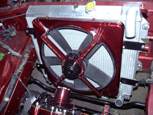
ok I bought the Pontiac 6000 fan (I bought the 4 cylinder one b/c it was cheaper and you said you don't think they're really any different) and I've been looking at it and looking at your pic for mounting. I have a Fluidyne radiator and it looks pretty similar to what you have in that pic.
Did your fan have four little mounting hole things on the 4 corners? Did you cut those off? And then you fabbed up those angled brackets and drilled holes into the side of the plastic shroud? And then you secured it with nuts, lockwasher, and bolt into the shroud itself, then nuts and bolts through the mounting points for the stock shroud. Am I understanding this right? I just don't want any mounting bolts to interfere with the operation of the fan and I want it to be secure.
Also, are you running a 40 amp relay? I was going to wire my (40 amp) relay like this:
85 - switched ground from power FC, 18 gauge
86 - constant +12V, 18 gauge (I guess I could run ignition switched but I guess it doesn't matter if the car needs to be on for the Power FC to switch the ground)
87 - constant +12V from battery , 10 gauge
87 - 10 gauge to positive wire on fan.
Also, do I need to reverse the polarity on the fan or anything like that? red wire is power and black is ground right?
Last edited by arghx; 07-29-08 at 02:15 PM.
07-29-08, 02:28 PM
#39
Engine, Not Motor
iTrader: (1)
Join Date: Feb 2001
Location: London, Ontario, Canada
Posts: 29,789
Likes: 0
Received 108 Likes
on
91 Posts
Yes. Basically I cut the stock mounting tabs off of the fan, smoothed down the plastic a little to make it look un-asstacular and then drilled holes in the shroud. I welded up some angle brackets but there's no reason you can't get them from the hardware store. M6 bolts and nuts secure them to the fan, and I think M6 as well fit in the stock shroud mounting tabs.
Pin 30 and 87 of the relay are the contacts, not 87 and 87 (87A is a NC contact, 87 is a NO contact).
The fan should run the correct direction if you connect the wires according to their colour. I always test first with a little 12V battery just to make sure because sometimes the wire colours are odd in OEM applications. Running it backwards won't damage it but of course it will blow in the wrong direction.

Thread
Thread Starter
Forum
Replies
Last Post
immanuel__7
2nd Generation Specific (1986-1992)
89
09-05-15 10:23 AM