
Single turbo vacuum diagram

Thread Starter
Joined: Apr 2005
Posts: 2,488
Likes: 8
From: California, SF
After extensive search, here is an attachment of:
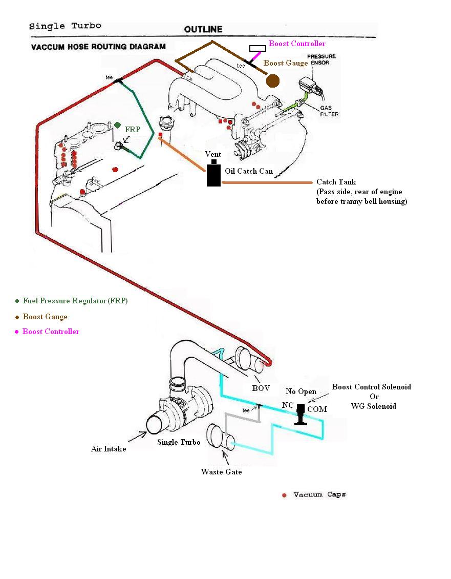
single turbo vacuum diagram
oil catch can routing
boost controller and boost gauge hook up
boost control solenoid and/or WG solenoid hook up
All in one that might be helpful for those who are interested converting to single turbo and wanted to add some goodies or two.
This attachment is only for SINGLE TURBO with ALL emission and charcoal canister/PCV system removed with OMP system blocked off.
The routing of the oil catch can is actually what Damian suggested. I just basically put it down on paper =),
If I have made ANY mistakes, please feel free in correcting me and I will remap this diagram for the needs of us who are going for single turbo. Hope this can be helpful!
-AzEKnightz


Thread Starter
Joined: Apr 2005
Posts: 2,488
Likes: 8
From: California, SF
Thank you.
If any1 need me to add more bell and whistles to this diagram I can do that. Let me know so I can do some research and make this as easy to comprehend as possible. Many diagrams out there either is incomplete or is confusing as hell. Hope this help out the future single turbo owners out there!
-AzEKnightz

Vacuum routing is always a debatable thing on at least a few issues, everyone should keep that in mind.
1) Your diagram caps off the atomization ports ("air bleeds") and the OMP injector air ports, all of which need to see fresh air (not manifold vacuum).
2) Those tees need to be BRASS, not plastic which could melt.
3) Mc-Master Carr sells high quality vacuum caps that will last much longer than the autozone stuff. http://www.mcmaster.com/ctlg/DisplCt...54344087987953 . part # 6448K74 are 5/32" caps, the most common size (aka 3.5mm)
4) The pressure source for the boost controller is debatable. Some have reported more boost stability by taking the pressure source from after the intercooler. Others run two different pressure sources, instead of one source with a tee. The side port source would come from before the intercooler, where the lack of a pressure drop will force the gate open earlier, while the solenoid (and thus the top port) pressure source comes from after the intercooler.
Thread Starter
Joined: Apr 2005
Posts: 2,488
Likes: 8
From: California, SF
1) Your diagram caps off the atomization ports ("air bleeds") and the OMP injector air ports, all of which need to see fresh air (not manifold vacuum).
2) Those tees need to be BRASS, not plastic which could melt.
4) The pressure source for the boost controller is debatable. Some have reported more boost stability by taking the pressure source from after the intercooler. Others run two different pressure sources, instead of one source with a tee. The side port source would come from before the intercooler, where the lack of a pressure drop will force the gate open earlier, while the solenoid (and thus the top port) pressure source comes from after the intercooler.
Guys, please input your information here like arghx. That way in the future, I can complete a much better, more detailed vacuum diagram for most of us.
Great response Arghx. Thank you.
-AzEKnightz

Thread Starter
Joined: Apr 2005
Posts: 2,488
Likes: 8
From: California, SF
Glad I can be of help =)
-AzEKnightz
Trending Topics
yeah I did a similar thing with LC1 wideband wiring. there were a bunch of threads but all the information was scattered and sometimes conflicting, so I compiled a complete wiring diagram based on what I read.
Why not just cap off the FRP? If you have an aftermarket FRP you can run it off the UIM. Instead of tapping into the Intercooler piping you could also run it from the UIM. I'm talking about the nipples that come out right after the elbow and throttle body. Just wanted to add that. Hope it makes some things easier. =]
Thread Starter
Joined: Apr 2005
Posts: 2,488
Likes: 8
From: California, SF
Why not just cap off the FRP? If you have an aftermarket FRP you can run it off the UIM. Instead of tapping into the Intercooler piping you could also run it from the UIM. I'm talking about the nipples that come out right after the elbow and throttle body. Just wanted to add that. Hope it makes some things easier. =]
As for the first nipple you were referring to, is it # 4 on the picture i've attached below? I just wanted to make sure before I fix the diagram =).
Thanks in advance.
-AzEKnightz
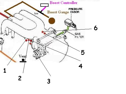
I'm pretty sure that 4 works.
I think that all 4 of those nipples work, however, I'm not sure. Right now I've got my lines running off of all 4 of those though. I haven't actually tapped into my intercooler piping or anything.
I think that all 4 of those nipples work, however, I'm not sure. Right now I've got my lines running off of all 4 of those though. I haven't actually tapped into my intercooler piping or anything.
Senior Member
Joined: Oct 2007
Posts: 453
Likes: 0
From: New Zealand
I am about to write up some full instructions on the single turbo conversion, i have compiled most of the info from various sites and just need to put it all together (minus all the dribble) so it is easily read and understood. Would you mind if I used your diagram as part of the instructions once it is finished??
Thread Starter
Joined: Apr 2005
Posts: 2,488
Likes: 8
From: California, SF
Thread Starter
Joined: Apr 2005
Posts: 2,488
Likes: 8
From: California, SF
I am about to write up some full instructions on the single turbo conversion, i have compiled most of the info from various sites and just need to put it all together (minus all the dribble) so it is easily read and understood. Would you mind if I used your diagram as part of the instructions once it is finished??
-AzEKnightz
Thread Starter
Joined: Apr 2005
Posts: 2,488
Likes: 8
From: California, SF
-Eric
So I am starting to plan my simplifying out as I all the intake and exhaust portions off for a single conversion. It seems that the first picture is still good except to use a separate line for the stock fpr on the UIM? I am running no emissions with everything blocked off including OMP. I am debating to cut all the extra nipples off the manifolds and filling the holes with a putty weld I used for the secondary plates. The excessive LIM has no nipples at all which would mean that the UIM would be the source for everything it seems.
WaterWeld Epoxy Putty | J-B Weld
WaterWeld Epoxy Putty | J-B Weld
Full Member

Joined: Jul 2013
Posts: 82
Likes: 4
From: Summerville, SC
I know this is an older post but, Wondering why there isn't a reference to the line that comes off the front of the turbo. I have oem Turbo2 and was wondering how to make everything work with stock wastegate and Tial blowoff valve. Project car from hell and want everything done right. Oh have a manual boost control too.

Thread
Thread Starter
Forum
Replies
Last Post
stickmantijuana
3rd Generation Specific (1993-2002)
5
Jan 11, 2016 04:08 PM
stickmantijuana
Single Turbo RX-7's
0
Aug 21, 2015 08:35 PM