Power FC THE power FC A/C fix!!!


 08-21-08, 11:20 PM
#102
The right type is:
(1) 12 vdc
(2) minimum contact requirement is a set of normally opened (NO) contacts, and can be low amperage (less than 1 amp).
(3) the above gives you 4 pins.
(4) some relays also have a set of normally close contacts (NC). This shares one with the NO. Thus we now have 5 pins.
(5) 2 pins go to the coil to energize it. When energized, the NC opens (1 controlled pin), and the NO closes (1 controlled pin) and in between and servicing both is the common 5th pin.
Even without any markings, using a ohm meter with a little understanding will enable one to determine which is which. After all I taught myself this stuff way before you-all were born and when transistors first came out. No chips or electronic games or PCs. Just tube and simple transistor radios. Boy you youngsters have it rough!
Also according to the book it look like my pressure switch is shot (no continuity the pins). btw can anyone with the nippon denso system tell me what color code wire goes to the pressure switch, blue black from a.c relay section to pressure side harness blue/black or Red black?
khris
09-15-08, 06:47 PM
#103
this is a very easy fix and you can get all the parts at radio shack for $29 total.
you need a relay part #275-0001 12vdc 40amp relay
telephone wire tap connectors part #64-3081 these are used to tap the ecu wires. they work amazing!
spade tongues terminals part #64-3033 these are for your ground wire.
quick splice connectors part #64-037 this is to tap your HOT wire from the Radio unit
Cimp on Quick Disconnects part #64-4040 these are for the relay.
now locate wire 1E (Violet wire) - it is the third wire from the end on connector one. Cut the wire 2” from ECU. On the harness side you will hook 1E to (86). On terminal (85) on the relay will go to ignition +. Terminal (87) will go to 1E that was cut on the Power FC side. Terminal (30) will go straight to chassis ground by the old ecu bracket . it took me about 1 1/2 hour to do it all and it works perfect! you will have to take your dash apart to tap the hot wire from your radio. also the "violet" wire looks more like beige since its all faded from the yrs. if you have any questions pm. and thanks for who ever came up with this fix! later
Last edited by bewtew; 09-15-08 at 06:59 PM.
12-23-08, 03:08 AM
#107
40k worth of fail
iTrader: (5)
Join Date: Mar 2001
Location: Hermosa Beach, CA
Posts: 1,312
Likes: 0
Received 0 Likes
on
0 Posts
Here is another link to my site with a diagram of the relay wiring. http://catfivemotorsports.com/power_fc_a.htm
 03-11-09, 06:50 PM
#109
Rear Admiral
iTrader: (3)
Join Date: Jul 2002
Location: St. Louis, MO
Posts: 1,685
Likes: 0
Received 0 Likes
on
0 Posts
this is a very easy fix and you can get all the parts at radio shack for $29 total.
you need a relay part #275-0001 12vdc 40amp relay
telephone wire tap connectors part #64-3081 these are used to tap the ecu wires. they work amazing!
spade tongues terminals part #64-3033 these are for your ground wire.
quick splice connectors part #64-037 this is to tap your HOT wire from the Radio unit
Cimp on Quick Disconnects part #64-4040 these are for the relay.
now locate wire 1E (Violet wire) - it is the third wire from the end on connector one. Cut the wire 2� from ECU. On the harness side you will hook 1E to (86). On terminal (85) on the relay will go to ignition +. Terminal (87) will go to 1E that was cut on the Power FC side. Terminal (30) will go straight to chassis ground by the old ecu bracket . it took me about 1 1/2 hour to do it all and it works perfect! you will have to take your dash apart to tap the hot wire from your radio. also the "violet" wire looks more like beige since its all faded from the yrs. if you have any questions pm. and thanks for who ever came up with this fix! later
06-02-09, 12:33 AM
#110
Oooo Shiney!

Join Date: Sep 2002
Location: WA & BC
Posts: 91
Likes: 0
Received 0 Likes
on
0 Posts
I did the A/C fix over the weekend. The A/C didn't work on ANY of the fan speeds before, now everything works perfectly! Instead of cutting up the harness or running wires all over the place, I just soldered a relay plug to Power FC main board. All the necessary connections are there. If you can find a smaller relay, everything can fit inside the case, but I didn't have one so it is just hooked up from the outside.
08-21-09, 04:51 PM
#111
Stud Service
iTrader: (3)
Join Date: Apr 2002
Location: Lancaster PA
Posts: 741
Likes: 0
Received 0 Likes
on
0 Posts
before any of you attempt the soldering, take the fan speed controller apart. I took it apart, gave the copper contacts a wipe and light sanding then I spread the springs apart a bit to make them push the contacts harder and presto..... I now have all fan speeds.
07-14-10, 08:35 PM
#115
r074r'/ |\|00B
iTrader: (14)
Join Date: Jan 2002
Location: KC, KS
Posts: 922
Likes: 0
Received 0 Likes
on
0 Posts
Nevermind, I have my AC working now!
Instead of running a seperate wire to the radio, I tapped wire 1B.
Instead of running a seperate ground wire, I tapped wire 4A (you could also use 4B or 4C).
ref: http://www.plxdevices.com/ECUDatabas..._RX7_93_95.pdf
Instead of running a seperate wire to the radio, I tapped wire 1B.
Instead of running a seperate ground wire, I tapped wire 4A (you could also use 4B or 4C).
ref: http://www.plxdevices.com/ECUDatabas..._RX7_93_95.pdf
07-14-10, 08:58 PM
#116

You may want to consider locating the grounding relay in the engine bay by the AC filter. You can interupt the wire to the AC pressure switch for the relay coil ground and the relay contact (to the PFC) and obtain a good Ign B+ for the relay coil several places close and obviously a ground anywhere. Picture shows mine in front of the battery. I got the Ign B+ from the AirCond Relay located in the relay box mounted on the chassis in front of the engine bay.
This is the same exact mod but in a much simpler and at a less invasive location.
IMG_2595.jpg?t=1279158373
This is the same exact mod but in a much simpler and at a less invasive location.
IMG_2595.jpg?t=1279158373
 08-07-10, 10:31 AM
#117
Eye In The Sky
iTrader: (2)
Join Date: Feb 2001
Location: In A Disfunctional World
Posts: 7,897
Likes: 0
Received 118 Likes
on
68 Posts
My FD has 120,000 miles on it since July 1992. Most of those were as a dayly driver up until 2003 when it became a weekend warrior. The AC and fan switch received a lot of use since I live in the Houston Tx. area.
Had an AC fix since 1999 when I got my first PFC. Lately when the car got very hot from being outside, fan speed 4 would intermittently work even with the relay. I took the switch apart and it was badly pitted, so I replaced it with a new one.
While doing it, I decided to check out the wiring system to try something new. If you look at the location of the wire going from the ECU, it goes to fan 1. This has a direct path to ground. As each fan speed increase, another resistor is added to the ground path. At fan 4 there are 3 resistors in the path. So why didn�t Mazda put the ECU wire at fan speed 3, this way at the most only 2 resistors are used in any path. This would insure a lower resistance path and help with the aging process. So I thought I might try this as a new mod.
So I started checking the wiring using the manual. Even with my electronics training and many years experience, I finally gave up because the manual does not match reality. The wiring for the switch matches. The resistor pack located on the AC unit has different values than what is in the manual, and there was no diode. Verified by sight and impedance checking from the switch. Maybe it is true only for the cars with the AC installed at the factory. The wire from the fan switch that goes to the A/C switch did not function as shown in the schematic. The wire from the A/C switch to the ECU also functioned differently. That is when I gave up!
If I could find a badly wrecked FD and was allowed to tear into it, maybe the truth could be found!
06-01-11, 09:01 PM
#120
Passenger
Posts: n/a
I have tried the Power FC wire fix for the AC and no luck. I didnt use the same diodes as the directions say so IDK if that is the problem.
When the car is off and your have the ignition open and turn on the AC the AC fan kick on in the front of the car, but not the inside blower.
When the car is on I get an idle fluctuation when i turn the AC on and off. I however dont get the recirculating light nor the AC lights to light up on the AC panel.
Does this mean anything to anyone or where I can find the fix?
06-01-11, 10:06 PM
#121
Eye In The Sky
iTrader: (2)
Join Date: Feb 2001
Location: In A Disfunctional World
Posts: 7,897
Likes: 0
Received 118 Likes
on
68 Posts
Download the wiring and AC manuals and check it all out.
http://foxed.ca/foxed/index.php?page=rx7manual
Otherwise take it to a mechanic.
http://foxed.ca/foxed/index.php?page=rx7manual
Otherwise take it to a mechanic.
06-01-11, 11:09 PM
#122
Passenger
Posts: n/a
Download the wiring and AC manuals and check it all out.
http://foxed.ca/foxed/index.php?page=rx7manual
Otherwise take it to a mechanic.
http://foxed.ca/foxed/index.php?page=rx7manual
Otherwise take it to a mechanic.
I was just trying to find out what other people have found out so I can try it. Obviously if I am on here asking it means I really dont want a mechanic tearing apart my car.
If no one can give me an answer or a clue as to what I can do then i guess i will never have AC.
Thanks for your help though
 06-02-11, 10:51 AM
#123
Passenger
Posts: n/a
I also tried a ground from the red wire to the support brace behind the dash.
When the AC is on and on 1 and 2 fan speed i get the following on my PFC
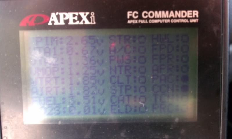
When I put it on fan speeds 3 and 4 I get the ELD light on the PFC, what ever that means
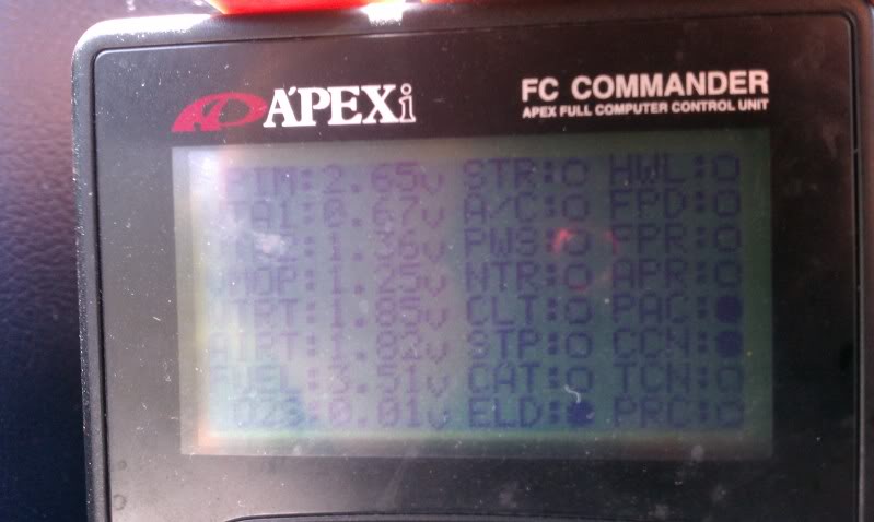
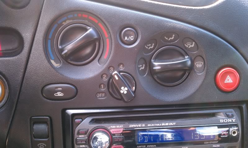
Also my dash looks like below with no lights or anything turning on for the AC
When the AC is on and on 1 and 2 fan speed i get the following on my PFC
When I put it on fan speeds 3 and 4 I get the ELD light on the PFC, what ever that means
Also my dash looks like below with no lights or anything turning on for the AC
06-05-11, 11:54 AM
#124
Mr. 2dude, Did you try the ground relay fix (some different ways of doing this are referred to in this thread)? This is the only fix I know of that works. Have had it for many years and no issues.
06-05-11, 10:47 PM
#125
Eye In The Sky
iTrader: (2)
Join Date: Feb 2001
Location: In A Disfunctional World
Posts: 7,897
Likes: 0
Received 118 Likes
on
68 Posts
The blower fan works separately from the AC. All the AC switch does is ground out an ECU pin through the switch.
So forget about the AC and check out the fan circuit. Start with the fuse and relay.
If you can not handle wiring schematics, then you will need a mechanic to do it.
"Life sucks, then you die!"
So forget about the AC and check out the fan circuit. Start with the fuse and relay.
If you can not handle wiring schematics, then you will need a mechanic to do it.
"Life sucks, then you die!"