When you click on links to various merchants on this site and make a purchase, this can result in this site earning a commission. Affiliate programs and affiliations include, but are not limited to, the eBay Partner Network.
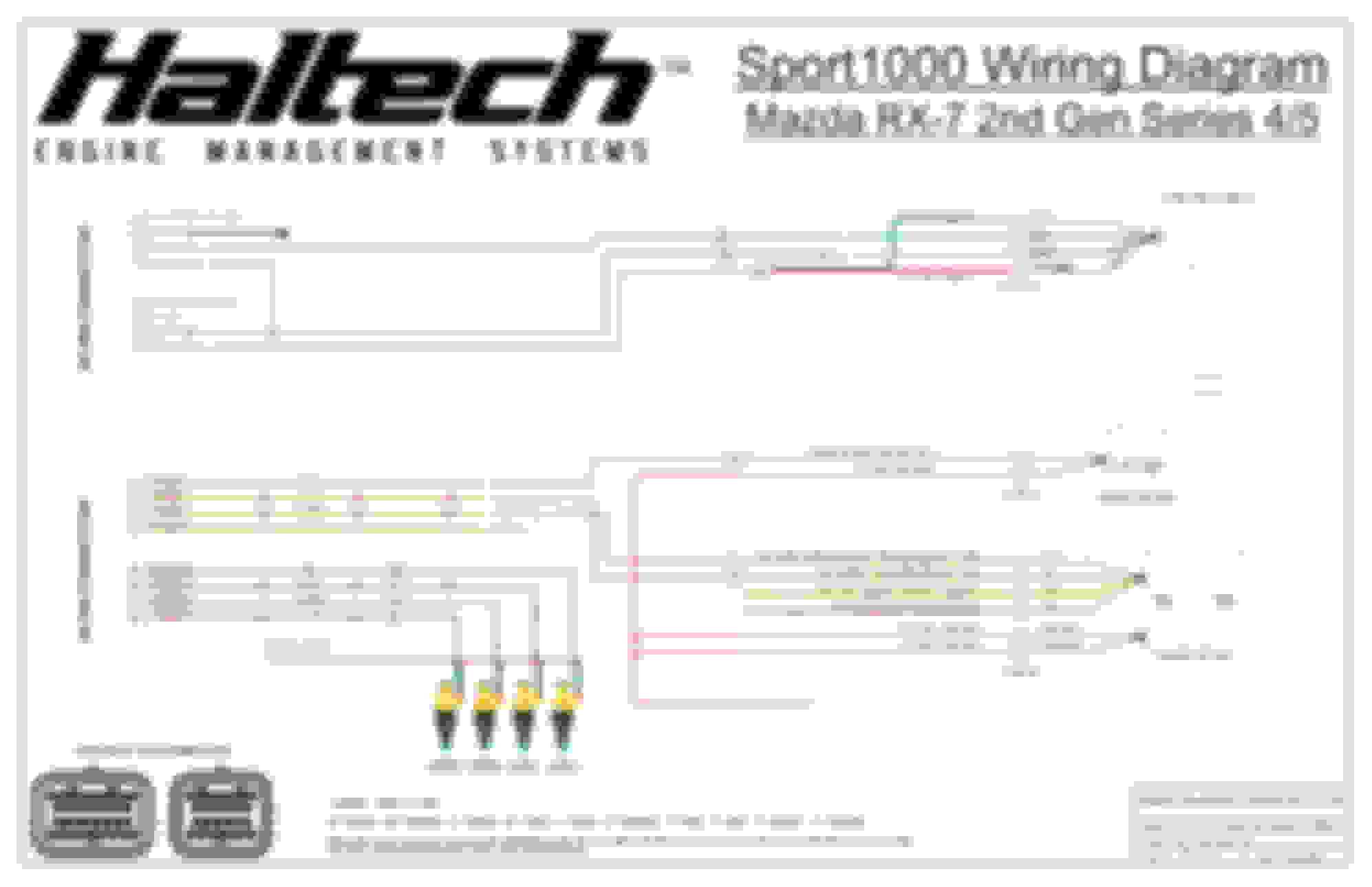
Hello all. I posted this in my build thread and at the time didn’t even realize there was a section dedicated to Haltech so maybe it’s better here. I bought an ECU connector and am making my own patch harness to connect my PS2K to the stock harness of my S5. I figured a patch harness was easier than trying to lay upside down on the passengers floor and repin the original. Sure I could buy a pre made one or a flying lead harness, but this project is more about the journey than the destination. Anyways, I think I have most of the major wiring figured out but I'm having trouble with the CAS. The manual shows the red and green (positives) tied together but the haltech does not want that. Am I missing something simple or do I just find an unused wire in the harness so i can split them? Also wouldn't mind if someone more in the know looked what I have over and point out anything else i may be missing. Obviously, this is just injectors, coils, and CAS. I included a sample from the manual to show what I'm talking about with the CAS wiring. I threw this together today and included the stock ECU locations where I will be connecting.
Last edited by Locoelectrician; Sep 13, 2018 at 08:00 PM.
Reason: Spelling error
It’s sorted. The wire colors on the Hal tech schematic are only good up until the CAS connector, then they switch places on the S5 engine harness. Here is the updated schematic in case anyone is ever searching and needs it.
Is there a reason why your Pin 11 isn't hooked up for 12v switched? How are you supplying power to your haltech?
That drawing was just for the CAS. The rest of the patch harness isn�t illustrated there. At the time I was just trying to get the CAS straight so I made the drawing as simple as possible.
That drawing was just for the CAS. The rest of the patch harness isn�t illustrated there. At the time I was just trying to get the CAS straight so I made the drawing as simple as possible.
Oh ok. How did you wire up your OMP? I'm trying to wire mine up but I'm confused between the OMP stepping motor and OMP position sensor. The stepping motor has 4 pins and the position sensor has 1 pin. I can't seem to find a diagram anywhere.