
JDM wiring harness on a spec


Aviation Machinist Mate

Joined: Jul 2006
Posts: 78
Likes: 12
From: SAN DIEGO
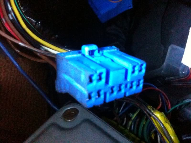
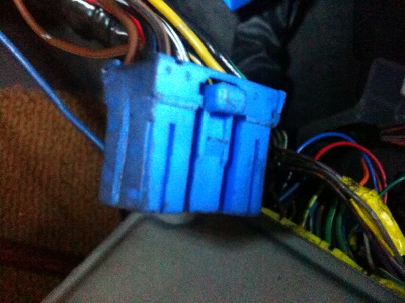
i did before and its alot of work. first you need to modify the (blue connector on the jspec engine harness) x-05 connector to fit on the dash connector, re-pin blk/yel wire x-05 jspec harness to blk/org dash, this is the power source for the injectors, then also if you dont want the fuel thermo check light on, you have to re-pin the brwn/yel wire from the jspec x-05 connector and pin it to x-14 connector blue wire.

If you can please explain more about what exactly needs to be done.Im pretty close to the end of the swap and I was under the assumption it was only the 12 wire blue connector that needs work.
Aviation Machinist Mate
Joined: Jul 2006
Posts: 78
Likes: 12
From: SAN DIEGO
ORIGINAL PIN DIAGRAM OF USDM X-05 (F) TO X-05 (EM) CONNECTOR
X-05 FRONT 10 PIN CONNECTOR
| G |BL/G|XXXX XXXX| V/W | Y |
|G/W|W/G| B/W | G\B | B/O | BR/W |
X-05 USDM (EM)10 PIN CONNECTOR
|B/L|BR/B| XXXXX | Y | B/G |
|BR | R |B/W|W/L | B/Y |BR\W|
X-05 JDM (EM)12 PIN CONNECTOR
| B/L |BR/B | Y | XXXXXXXXXXX| B/G | W/L |
|BR | R | B/W | BR\Y | B/Y | XXX |BR/W|
NOTE: PLEASE REMOVED ALL PINS BEFORE STARTING THIS MODIFICATION. NEXT, YOU NEED TO MODIFY THE JDM X-05 12 PIN (BLUE) CONNECTOR AND MAKE IT TO A 10 PIN CONNECTOR. I USED A DREMEL TO CUT MY OFF. CUT THE B/L AND BR PIN CONNECTOR OFF.
X-05 USDM (EM)10PINS
B/G - EGR
Y- 1ST GEAR
BR/B - TPS
BR/W - PRESS SENSOR
B/Y - INJECTOR 12V
W/L - COOLING RELAY
B/W - SOLENOID VALVES
R - 2ND GEAR SWITCH
BR - TRANNY
B/L - EGR
X-05 JDM (EM)11 PINS
B/L-EGR
BR/B - TPS
Y - 1ST GEAR
BR - TRANNY
R - 2ND GEAR SWITCH
BR/Y - FUEL TEMP SENSOR
BR/W - PRESS SENSOR
B/Y - INJECTORS 12V
B/W - SOLENOID VALVES
B/G- EGR
W/L - COOLING RELAY
NOTE: BR/Y WIRE(FUEL TEMP SENSOR) GOES TO X-14 AND PIN IT TO THE BLUE WIRE ON X-14 (white connector under the DASH).
Trending Topics

Aviation Machinist Mate
Joined: Jul 2006
Posts: 78
Likes: 12
From: SAN DIEGO

Can some please post up what each of US 10 pin NON EMISSION connector wires stand for. I need to know so i can match them up.
Ive been searching for hours through the forum and fsm with no definition to the colors
Ive been searching for hours through the forum and fsm with no definition to the colors
do you have the jdm male connector? I had one when i bought my clip, all I did was cut off the male connector and solder it according to the same color off the USDM one. After that it just plugs right in.
Aviation Machinist Mate
Joined: Jul 2006
Posts: 78
Likes: 12
From: SAN DIEGO
did you follow the step above, im running the same set up your doing ( usdm front and jdm em harness. you dont match the wires, just follow the step i did and you should be good. trust me, ive check where all the wires go one by one and prolly more than 30x.
for example usdm front to jdm EM
G - BL
BL/G - BR/B
V/W - Y
Y - B/G
ORIGINAL PIN DIAGRAM OF USDM X-05 (F) TO X-05 (EM) CONNECTOR
X-05 FRONT 10 PIN CONNECTOR
| G |BL/G|XXXX XXXX| V/W | Y |
|G/W|W/G| B/W | G\B | B/O | BR/W |
X-05 USDM (EM)10 PIN CONNECTOR
|B/L|BR/B| XXXXX | Y | B/G |
|BR | R |B/W|W/L | B/Y |BR\W|
Tundra driver, Rx-7 pilot
iTrader: (1)
Joined: Nov 2004
Posts: 150
Likes: 0
From: Everett, Washington
I apologize for resurrecting a dead thread. So im lame terms, should I be cutting off the JDM x-05 connector from the main engine harness and splicing in the USDM x-05 connector, splicing COLOR to COLOR, EXCEPT for the one brown/yellow wire? Or is there a certain wire from the JDM harness that needs to go to the USDM x-14 white connector with a blue wire?
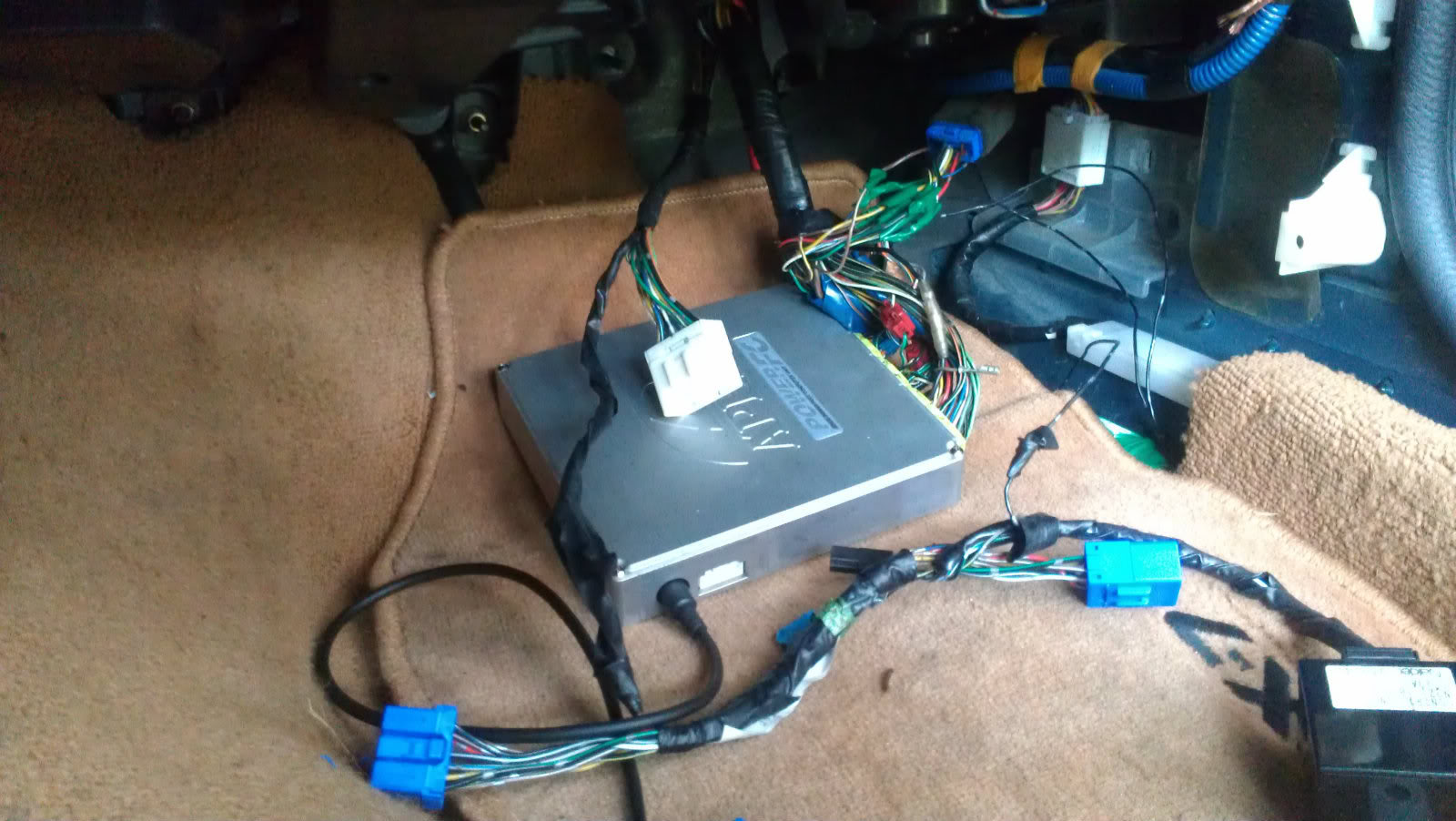
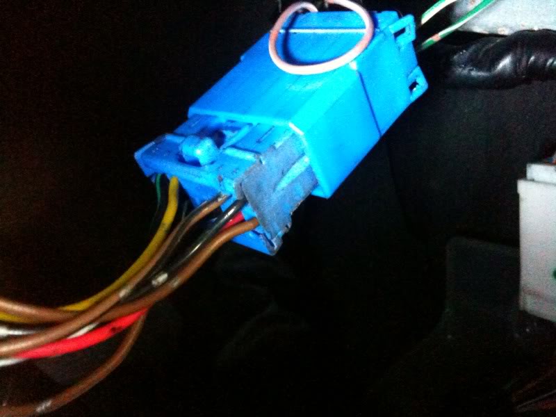
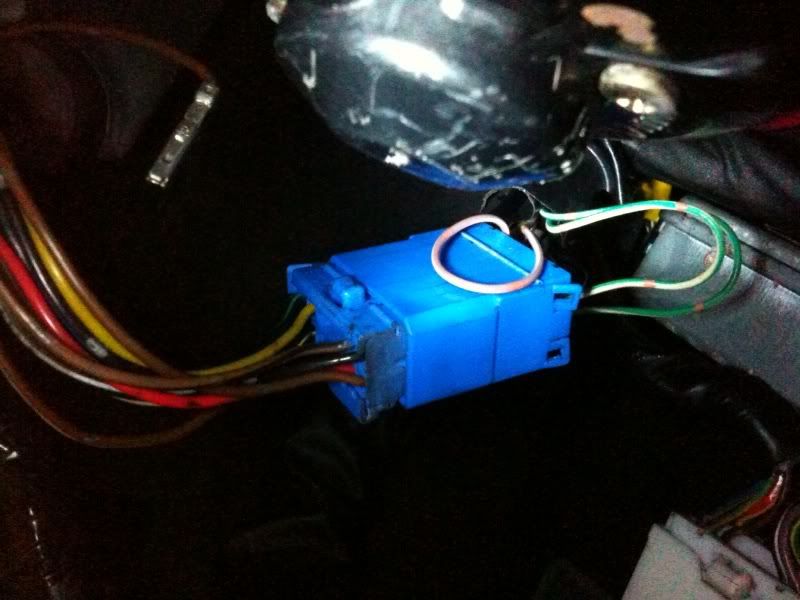
Also, what exactly is this white connector here, and where does it need to be connected?
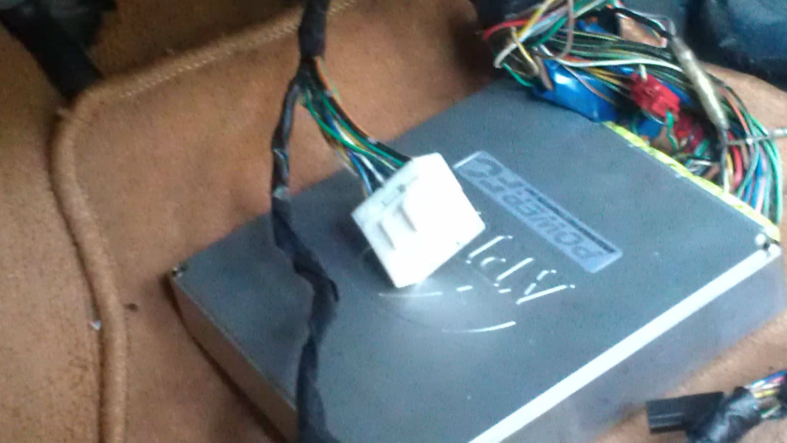
I also notice that the x-05 connector does not need this extension piece to fit into that other part. Is it necessary to be hooked up? it looks like in the picture above they have it hooked up directly. I apologize again for being so electrical illiterate. Someone to coach me through this part would be greatly appreciated. I am thinking this is the reason I have no power to my injectors.
Also, what exactly is this white connector here, and where does it need to be connected?
I also notice that the x-05 connector does not need this extension piece to fit into that other part. Is it necessary to be hooked up? it looks like in the picture above they have it hooked up directly. I apologize again for being so electrical illiterate. Someone to coach me through this part would be greatly appreciated. I am thinking this is the reason I have no power to my injectors.

If it fits in there then why would you want to swap it? I think they made the change to the bigger connector on cars 96 and up. None of the wires from the blue connector go into a different connectors.
I would just make sure that the color of the wires match on each side, also I would avoid splicing wires there especially on a connector that can be de-pinned so easily...
The white connector plugs into another female down there near the firewall you just have to look for it.
I would just make sure that the color of the wires match on each side, also I would avoid splicing wires there especially on a connector that can be de-pinned so easily...
The white connector plugs into another female down there near the firewall you just have to look for it.
Tundra driver, Rx-7 pilot
iTrader: (1)
Joined: Nov 2004
Posts: 150
Likes: 0
From: Everett, Washington
If that's the case then what were those previous guys talking about with connector x-14? Also does anybody know what that white connector is? I do realize it has to connect somewhere...