
DaleClark's guide to converting a KPH speedo/odo to MPH!

Thread Starter


Joined: Jan 2002
Posts: 15,622
Likes: 2,723
From: Pensacola, FL
SO happy I FINALLY figured this joker out.
OK, so your odometer or speedometer in your car is dead as a hammer. You buy a Japanese instrument cluster, and while it works, it shows your speed and odometer readings in kilometers. Novel, but not that great.
So, you hit up my writeup here -
https://www.rx7club.com/3rd-generati...meter-1011051/
and calibrate your KPH speedo so the KPH numbers actually mean MPH. So, when it says 40 kph, you're doing 40 MPH. And, the odometer says KPH and seems to be still reading in kilometers. And, your original odometer reading is now gone.
Time to fix ALL that.
First off, you will need to do some soldering. It's pretty light solder work at least. Get a good soldering iron, some solder, and a solder sucker or desoldering wick. You'll also need an XActo knife.
Note: the gauge face is VERY delicate and easily gets greasy with finger prints. Make sure your hands are clean and try to only hold the speedo from the side.
So, here's our candidate -
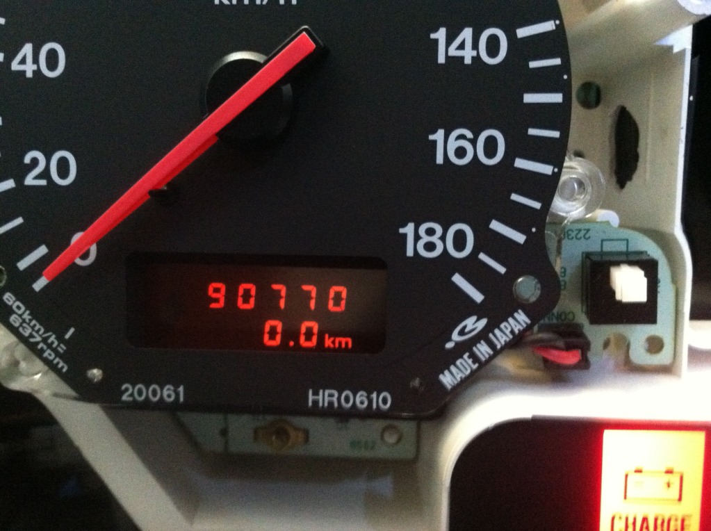
I bought this cluster off Ebay. Plugged it into my car, all looks good. Drove around the block, and it's definitely reading in kilometers.
So, I found 2 differences between my US instrument cluster and the JDM instrument cluster. I modified the JDM cluster to be like the US one, the first mod didn't do it, the second did. Now, you might just need to do the second mod and that's it. That's how I will present this mod.
OK, take your instrument cluster apart and remove the speedo module. There are 4 screws that hold it in from the back. I also remove the little circuit board that goes to the odometer reset button and leave it attached. There is also a black plastic cover on the back held on with one screw, remove that then disconnect the ribbon cable underneath. Flip it over and look at the back. You're looking for a section with 4 pads with 2 resistors, they're marked R14 through R17 -
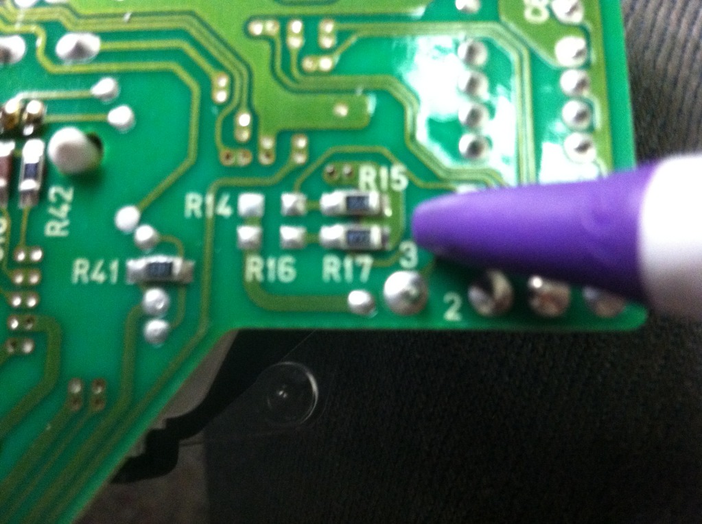
OK, see the 2 small black boxes at R15 and R17? That's how it should look for US-spec. The JDM cluster has one on the left and one on the right. You need to desolder the one on the left and move it to the right - again, we want to make it look like the picture above.
Removing the resistor is tricky, it's a surface mount resistor and is VERY tiny. It's also glued to the circuit board. I removed as much solder as I could on each side with the solder sucker, then scored the top and bottom of the resistor with an Xacto knife. I then heated one side and worked the Xacto knife under the resistor, it eventually worked free. Then heated up the other side and got it to come up. I placed it in its new home and touched a dab of solder to each side, good to go. The solder traces are pretty close together, don't use a big dab that will contact 2 solder points and short it out, that would be Bad.
At this point, I would try it out in your car to see if you don't need to do the second step. Or, just do the second step anyhow .
.
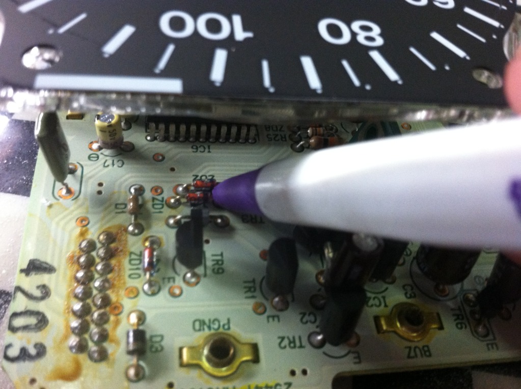
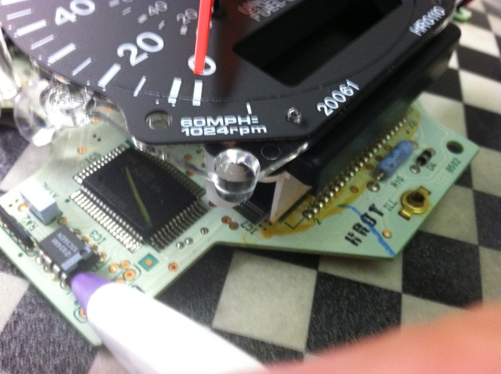
For the second step, go to Radio Shack and get a pack of 2 12v Zenier diodes. It was like a dollar for the pack, and my crappy Radio Shack had plenty in stock. Look at the front side of the odometer above the gauge face, there's a spot marked ZD1 and ZD2. We need to add one diode into the spot that doesn't have one.
The two pads for the missing diode have a small bit of solder covering the holes the diode needs to go through. With your soldering iron, warm it up and the solder should flow out of the hole and open it up. Feed the diode's legs in from the front side and solder it in place. The line on the diode shows what way the current travels, we want it to be in there just like the other diode that's already installed. Here it is done -
OK, so pop it in your car and test your work. Make sure to hook up that ribbon cable, without it the odometer won't work. Here's what I got -
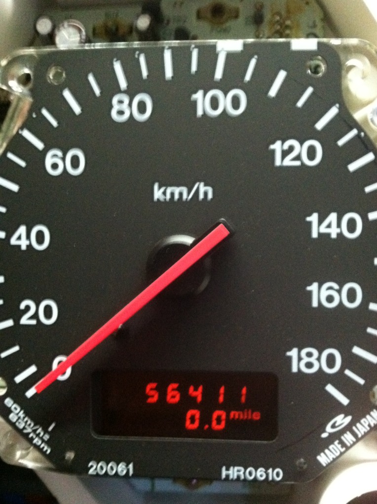
Yay! Miles per hour! Also, you'll notice the odometer reading has been converted from 91,xxx to 56,xxx - it converted the value stored to the proper reading.
OK, so you want to move your existing odometer reading from your original instrument cluster to the new one. I have discovered where this is stored, but I haven't done this yet. There is a small EEPROM on the board, over on the left front side. That stores the odometer reading.
The chip is labeled "93c56en". It's here -
There are 8 legs that need to be desoldered. Desolder the old one as well, solder it on, and there ya go. I have NOT tested this, but I have done extensive Googling on the topic, and other cars with digital odometers use this exact chip to store the reading, so I'm confident that this will work.
So, here's the steps, in summary -
- Pull instrument cluster from car
- Remove speedo from instrument cluster
- Move small surface mount resistor on back side to correct spot
- (may not need to be done) install new zenier diode on front side
- Test to make sure it's working
- Move 93c56en chip if necessary
- Install speedo back into cluster, install back in car
- Drive around and calibrate speedo with my how-to guide
I am SO EXCITED to have cracked this.
Also, I am available to do this to your cluster for moneys, PM me if interested.
Dale
OK, so your odometer or speedometer in your car is dead as a hammer. You buy a Japanese instrument cluster, and while it works, it shows your speed and odometer readings in kilometers. Novel, but not that great.
So, you hit up my writeup here -
https://www.rx7club.com/3rd-generati...meter-1011051/
and calibrate your KPH speedo so the KPH numbers actually mean MPH. So, when it says 40 kph, you're doing 40 MPH. And, the odometer says KPH and seems to be still reading in kilometers. And, your original odometer reading is now gone.
Time to fix ALL that.
First off, you will need to do some soldering. It's pretty light solder work at least. Get a good soldering iron, some solder, and a solder sucker or desoldering wick. You'll also need an XActo knife.
Note: the gauge face is VERY delicate and easily gets greasy with finger prints. Make sure your hands are clean and try to only hold the speedo from the side.
So, here's our candidate -
I bought this cluster off Ebay. Plugged it into my car, all looks good. Drove around the block, and it's definitely reading in kilometers.
So, I found 2 differences between my US instrument cluster and the JDM instrument cluster. I modified the JDM cluster to be like the US one, the first mod didn't do it, the second did. Now, you might just need to do the second mod and that's it. That's how I will present this mod.
OK, take your instrument cluster apart and remove the speedo module. There are 4 screws that hold it in from the back. I also remove the little circuit board that goes to the odometer reset button and leave it attached. There is also a black plastic cover on the back held on with one screw, remove that then disconnect the ribbon cable underneath. Flip it over and look at the back. You're looking for a section with 4 pads with 2 resistors, they're marked R14 through R17 -
OK, see the 2 small black boxes at R15 and R17? That's how it should look for US-spec. The JDM cluster has one on the left and one on the right. You need to desolder the one on the left and move it to the right - again, we want to make it look like the picture above.
Removing the resistor is tricky, it's a surface mount resistor and is VERY tiny. It's also glued to the circuit board. I removed as much solder as I could on each side with the solder sucker, then scored the top and bottom of the resistor with an Xacto knife. I then heated one side and worked the Xacto knife under the resistor, it eventually worked free. Then heated up the other side and got it to come up. I placed it in its new home and touched a dab of solder to each side, good to go. The solder traces are pretty close together, don't use a big dab that will contact 2 solder points and short it out, that would be Bad.
At this point, I would try it out in your car to see if you don't need to do the second step. Or, just do the second step anyhow
.For the second step, go to Radio Shack and get a pack of 2 12v Zenier diodes. It was like a dollar for the pack, and my crappy Radio Shack had plenty in stock. Look at the front side of the odometer above the gauge face, there's a spot marked ZD1 and ZD2. We need to add one diode into the spot that doesn't have one.
The two pads for the missing diode have a small bit of solder covering the holes the diode needs to go through. With your soldering iron, warm it up and the solder should flow out of the hole and open it up. Feed the diode's legs in from the front side and solder it in place. The line on the diode shows what way the current travels, we want it to be in there just like the other diode that's already installed. Here it is done -
OK, so pop it in your car and test your work. Make sure to hook up that ribbon cable, without it the odometer won't work. Here's what I got -
Yay! Miles per hour! Also, you'll notice the odometer reading has been converted from 91,xxx to 56,xxx - it converted the value stored to the proper reading.
OK, so you want to move your existing odometer reading from your original instrument cluster to the new one. I have discovered where this is stored, but I haven't done this yet. There is a small EEPROM on the board, over on the left front side. That stores the odometer reading.
The chip is labeled "93c56en". It's here -
There are 8 legs that need to be desoldered. Desolder the old one as well, solder it on, and there ya go. I have NOT tested this, but I have done extensive Googling on the topic, and other cars with digital odometers use this exact chip to store the reading, so I'm confident that this will work.
So, here's the steps, in summary -
- Pull instrument cluster from car
- Remove speedo from instrument cluster
- Move small surface mount resistor on back side to correct spot
- (may not need to be done) install new zenier diode on front side
- Test to make sure it's working
- Move 93c56en chip if necessary
- Install speedo back into cluster, install back in car
- Drive around and calibrate speedo with my how-to guide
I am SO EXCITED to have cracked this.
Also, I am available to do this to your cluster for moneys, PM me if interested
.Dale
Dale, If you need to move the mileage up to match, use a signal generator and set it so the speedo is doing 180MPH. It may take a little while but the mileage will tick up pretty quickly.
I used my signal generator I made in Electronics School and it worked like a charm. I always wanted to let it run to 999999 and see if it would flip back to zero, haven't tried it yet.
I used my signal generator I made in Electronics School and it worked like a charm. I always wanted to let it run to 999999 and see if it would flip back to zero, haven't tried it yet.
Thread Starter
Joined: Jan 2002
Posts: 15,622
Likes: 2,723
From: Pensacola, FL
There is also software out there that you can re-program the EEPROM with a new value. So, in theory, you can pull that EEPROM, put it in a programmer, and put whatever value you want into it.
Of course, tampering with this type of stuff is illegal. But, most of our cars are odometer exempt, but it isn't cool to put a lower reading speedo into a car with a lot of miles and try to sell it as such.
Dale
Of course, tampering with this type of stuff is illegal. But, most of our cars are odometer exempt, but it isn't cool to put a lower reading speedo into a car with a lot of miles and try to sell it as such.
Dale
Trending Topics
Dale, you continue to be my hero - seriously
Thanks for doing this. It opens up the possibility of using JDM KPH clusters. I had scratched all of these off of my list due to the issues you have now resolved. Thanks so much!
Thanks for doing this. It opens up the possibility of using JDM KPH clusters. I had scratched all of these off of my list due to the issues you have now resolved. Thanks so much!
RX Dragon
Joined: Sep 2012
Posts: 6
Likes: 0
From: South Africa JHB
HI Dale
I have a question or two...Nice write up !
Anyways, do you know if this will affect the Speed Cut out? what i mean is.... , speedo is in KM/h and the car cuts out at 180 Km/h, if i were to try changing to miles do you know if it might remove the limiter,... Running stock ECU.. i am from South africa and have a jap spec 96 FD mostly Stock.. thanks for any input you might have.
Thread Starter
Joined: Jan 2002
Posts: 15,622
Likes: 2,723
From: Pensacola, FL
Haha, thanks . You can have it read MPH, but that won't do you a lot of good if you're in a KPH country. There are quite a few aftermarket JDM speedos that read to 300 or 320 KPH, but you may be payin' for 'em.
Dale
. You can have it read MPH, but that won't do you a lot of good if you're in a KPH country. There are quite a few aftermarket JDM speedos that read to 300 or 320 KPH, but you may be payin' for 'em.Dale

Full Member
Joined: Jan 2011
Posts: 94
Likes: 0
From: Sweden
hey guys... nice write up for sure
but have a thing to ask.. about to get a UDSM cluster to put in my JDM car... well will only move the speedo �ver... but I need the ODO to read km, not miles... and keep it so it reads up to 180mp/h also, 280km/h... instead of buying those aftermarkes 300km/h speedos for LOTS and LOTS of money
will move over the EEPROM so the mileage is still correct for the chassie... what of the 2 solderings should I do to get this to be correct you think?
guess the speed signal needs to be untouched... only the ODO circuits needs some change
EDIT... now I read it again... and the soldering only fixes with the ODO? and the speedo output is totally up to the calibration thread? or am I reading this wrong? =)
Last edited by Wolf_; Feb 26, 2013 at 05:07 PM. Reason: EDIT!

Thread Starter
Joined: Jan 2002
Posts: 15,622
Likes: 2,723
From: Pensacola, FL
hey guys... nice write up for sure
but have a thing to ask.. about to get a UDSM cluster to put in my JDM car... well will only move the speedo �ver... but I need the ODO to read km, not miles... and keep it so it reads up to 180mp/h also, 280km/h... instead of buying those aftermarkes 300km/h speedos for LOTS and LOTS of money
will move over the EEPROM so the mileage is still correct for the chassie... what of the 2 solderings should I do to get this to be correct you think?
guess the speed signal needs to be untouched... only the ODO circuits needs some change
EDIT... now I read it again... and the soldering only fixes with the ODO? and the speedo output is totally up to the calibration thread? or am I reading this wrong? =)
but have a thing to ask.. about to get a UDSM cluster to put in my JDM car... well will only move the speedo �ver... but I need the ODO to read km, not miles... and keep it so it reads up to 180mp/h also, 280km/h... instead of buying those aftermarkes 300km/h speedos for LOTS and LOTS of money
will move over the EEPROM so the mileage is still correct for the chassie... what of the 2 solderings should I do to get this to be correct you think?
guess the speed signal needs to be untouched... only the ODO circuits needs some change
EDIT... now I read it again... and the soldering only fixes with the ODO? and the speedo output is totally up to the calibration thread? or am I reading this wrong? =)
But, basically everything I said to do with the cluster you can probably back out. I just made a Japanese cluster match what a US cluster is like, so if you make a US cluster match up with a Japanese you should be good.
You'd still have the 180kph problem. I guess with the US cluster with the KPH readings in the center you could go by that but it's a little goofy. Or just don't speed
.Dale
Full Member
Joined: Jan 2011
Posts: 94
Likes: 0
From: Sweden
Well my jdm cluster works fine, just want to see more then the 180km/h, well After about 15seconds with my last BPU setup I had to try seeing what the pfc commander said... :-P and now with a singelturbo I guess it'll be even less ;-)
But still, the usdm speedo shouldn't need calibration, only remove the resistor and move that little thingy over to the left, going backwards in your guide would make my ODO read km instead of miles, right? :-)
But still, the usdm speedo shouldn't need calibration, only remove the resistor and move that little thingy over to the left, going backwards in your guide would make my ODO read km instead of miles, right? :-)
Full Member
Joined: Jan 2011
Posts: 94
Likes: 0
From: Sweden
hmm jsut one question Dave
whom of the resistors was to the left, is it one on R15 and one on R16? =)
and what diod was missing, the Z01 or Z02?
Have a buddy here in sweden that has to do this mod soon, I havent removed mine yet so can't look at how it looks on the JDM cluster
whom of the resistors was to the left, is it one on R15 and one on R16? =)
and what diod was missing, the Z01 or Z02?
Have a buddy here in sweden that has to do this mod soon, I havent removed mine yet so can't look at how it looks on the JDM cluster


Full Member
Joined: Mar 2011
Posts: 149
Likes: 1
I tried this on my 2002 gauge cluster not the spirit R. I followed your guide step by step. I decided to do both mods instead of putting it back int the car to test it then pull it again. When i finished adding the diode. My ODO was not coming on at all. I was a little worried and drove the car and noticed that neither my tach or the speedo worked.
Can you help me hopefully diagnose what is the case of this? Thanks in advance,
Can you help me hopefully diagnose what is the case of this? Thanks in advance,
Thread Starter
Joined: Jan 2002
Posts: 15,622
Likes: 2,723
From: Pensacola, FL
If both aren't working, you could have popped a fuse or didn't hook up one of the electrical connectors properly. The tach is a SUPER simple circuit, the 3 screws that hold it in give it power, ground, and signal. If the tach isn't working and it previously was, something isn't hooked up right.
Also, turn on your parking lights and see if the cluster lights up. If not, that will give something else to troubleshoot.
Mind you, I've only done this mod to an earlier JDM cluster, they may have things different with the later clusters. I'm no electronics genius, I just compared the two and made the changes.
Dale
Full Member
Joined: Mar 2011
Posts: 149
Likes: 1
If both aren't working, you could have popped a fuse or didn't hook up one of the electrical connectors properly. The tach is a SUPER simple circuit, the 3 screws that hold it in give it power, ground, and signal. If the tach isn't working and it previously was, something isn't hooked up right.
Also, turn on your parking lights and see if the cluster lights up. If not, that will give something else to troubleshoot.
Mind you, I've only done this mod to an earlier JDM cluster, they may have things different with the later clusters. I'm no electronics genius, I just compared the two and made the changes.
Dale
Also, turn on your parking lights and see if the cluster lights up. If not, that will give something else to troubleshoot.
Mind you, I've only done this mod to an earlier JDM cluster, they may have things different with the later clusters. I'm no electronics genius, I just compared the two and made the changes.
Dale