When you click on links to various merchants on this site and make a purchase, this can result in this site earning a commission. Affiliate programs and affiliations include, but are not limited to, the eBay Partner Network.
The crankcase pressure that fills up my catch can at least half way with the nasty oil and water mixture in less than 5,000 miles.
The setup you suggested is a catch can too. The random container thing works but looks ghetto. I'm all for function over form but I'll spend $20 on an ebay catch can for the sake of not having to keep a stack of empty coke bottles in my garage And believe it or not a lot of people actually get the catch can for appearance purposes.
But again, don't 3 hoses go into the stock plastic PCV? We're only talking about the position of 2 of them so where does the 3rd one go?
The stock purge valve is vacuum controlled so that it only bypasses under high vacuum. The top port opens the two bottom ports and allows flow through them. One port has a small orifice which is calibrated to control flow so that engine operation isn't effected from excess air when the valve opens.
When using a catch can, I just replace the valve with a generic PCV valve from the parts store.
Originally Posted by KhanArtisT
There is no need to run vacuum through the catch can. The only advantage to doing this would be longer intervals in draining the can, the primary job of the setup is to vent crankcase pressure. I feel it adds extra plumbing and increases the risk of vacuum leaks but if the car is daily driven it would be worthwhile.
Running vacuum through the catch can keeps the stock crankcase venting function in place. Air flows from the nipple in the center iron to the center of the engine around the eccentric, capturing all the junk the builds up on the way as it flows back up the oil filler neck, out through that nipple and into the intake to be burned. Just plumbing both nipples to a catch can without this circulation allows all that nasty to build up. The evidence of this is the white junk that accumulates under the oil cap and the rust formed in the oil filler neck.
Also the whole point of running a catch can is to keep the dirty oil/water mixture from being sent to the engine which causes carbon buildup and degrades the fuel octane level (more so than it already is with the OMP).
The point of a catch can is to prevent excessive oil from entering the intake. As would be experienced in an engine running high boost or one under fairly high G-forces. Or engines built a little loose or worn out. There is no reason not to both incorporate the function of the catch can and the PCV function needed to keep the crankcase clean.
Originally Posted by PvillKnight7
What crankcase pressure? This isn't a piston engine. Most of these old rotaries are so worn out and have so much blow by the oil is quickly contaminated with fuel. I wouldn't even bother with a catch can. Just run 5/8" fuel line from the center iron nipple to a soda bottle and wrap a rag and zip tie around the neck to serve as an air filter.
Crankcase pressure will build up from natural gas bypass from side seal clearance or boost pressure. Excessive fuel will exacerbate the problem as the oil film is washed from the irons.
Aaron, can you please comment on the routing in the pic provided.
I've been toying around with this for quite some time as I do need a catch tank of sorts but don't want to burn all the contaminents off. I'd rather capture them to be emptied. My idea consists of basically a double chamber tank. The first chamber if you will is fitted with a breather filter and is plumbed to the nipple on the center iron.
The nipple on the oil filter neck would be plumbed to the bottom of the second chamber. This chamber would be filled with a steel wool material and have a drain as well. This chamber would have a smaller sintered type filter on it. The second chamber is routed to the TID.
The theory is the vac created will circulate air through the crankcase but the steel wool will capture any crap in the second chamber and not allow it enter the intake.
Since the contaminates are in vapour form, I don't know how well that would work. They would probably pass straight through the steel wool filter. What's wrong with burning the stuff off?
The crap that's getting caught in my can right now isn't in vapor form, I believe that I also have oil sloshing up the oil filler on hard turns Regardless of how hard I push the car in a straight line, there seems to be minimal buildup in the can, as soon as I hit the backrds or the track, it's virtually overflowing. I also have other problems with such a cold running engine and the moisture that's in there so I need to address this.
There's nothing really wrong with burning the vapor as long as it's consistent. What I don't want to see happen is the intercooler become saturated with oil. Given the rate that I can fill the catch tank, it'll soak the intercooler rather quickly. Something that I'd like to avoid which is the reason for the double chamber and something to slow it down and catch it.
So when the upper nipple on the filler neck is connected to a vac source via a PCV valve, and the catch can is connected to the nipple on the center iron, no oil would be vented to the catch can while the car is running, correct? It would be sucked into the engine and burned? So I'm assuming the catch can would only collect excess oil once the car is shut off?
Also, wouldn't this setup act as a vacuum leak at idle? Even if air is drawn from the TID, it is still bypassing the throttle body, which seems like it would cause a high idle.
I just have the hose going to the filler neck, yes I think it can be better going to the center iron or even have heard that the proper way is to run 2 cans, but I aint running NASCAR with this thing.
So i just got mine installed and one hose it went from the center iron to the catch can and the other nipple on the catch can is left open as a breather.
Ok so one hose from center iron nipple to input on oil catch can and the ouput from oil catch can open.
But What happens with the hose that was connect it to the center iron nipple????
I have toyed with the catch can or no catch can theory for so long now. 🤦🏻♂️ i think im ready to finally install, but still not sure which way i want2 do it.
There are quite a few threads on this topic, I would suggest trying to search since this has been covered.
You will basically end up running your catch can to the oil filler and/or the breathing tube on the engine block. Then the other hose on your can goes to atmosphere....
Sup.
Guy from the future here just to say it's always fun to land on these threads while actually doing a search and immediately see "why don't you do a search" lol
It's also quite amusing when a thread lays out with exactly how something should be set up, complete with explanations why, and then there are a bunch of posts after that just saying "I stuck a hose on it and let it drip all over".
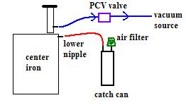
The proper way to connect a catch can is to run the lower nipple on the center iron to the catch can. Then have the top connection of the catch can draw air from a little filter (standalone) or from the TID (stock ECU). The nipple in the filler neck then gets connected to a vacuum port on the intake through a PCV valve.
This preserves the proper fresh air flow through the crankcase and prevents moisture buildup.
Originally Posted by PvillKnight7
Here's a pic for you visual learners.
Since this thread has been resurrected once (and has good info), I'll do it again.
Where would the hose from the factory charcoal canister factor into this system? From the factory it's T'ed into the hose from the center iron nipple to the TID. Should I do the same and have it run into the catch can, then have the catch can outlet run into the TID? Is is safe to have fuel vapor in the catch can?
Sorry to be annoying, but I have doubts about the setup I've arrived at. I connected the charcoal canister to the upper nipple as recommended to avoid oil being pushed into it, and I've added the catch can inline with the hose coming off of the lower nipple.
It's my understanding the the lower nipple is meant to draw air in to the crankcase, and the air the air then flows out of the upper nipple into the PCV. However, with the factory check valve in place on the TID as I have it now, it appears there's no way for air to be drawn into the lower nipple. Am I meant to remove that check valve?
Factory setup:
How I have it now (changes circled in red, the catch can is the vertical rectangle in the lower nipple hose):
I'm using the factory 3-nipple PCV valve, I couldn't find a generic 2-nipple PCV valve that matches the vacuum nipple sizes on the car


 And believe it or not a lot of people actually get the catch can for appearance purposes.