
Oil Catch Can setup

Oil Catch Can setup
Whats up guys can anyone show me detailed pics of their oil catch can setup. I got an ebay catch can but I have no idea how to hook it up. Any help will be much appreciated.
This is the catch can I bought.......
http://cgi.ebay.com/ebaymotors/Unive...Q5fAccessories
This is the catch can I bought.......
http://cgi.ebay.com/ebaymotors/Unive...Q5fAccessories
Last edited by Arnomardi; Mar 30, 2010 at 11:26 AM.
There are quite a few threads on this topic, I would suggest trying to search since this has been covered.
You will basically end up running your catch can to the oil filler and/or the breathing tube on the engine block. Then the other hose on your can goes to atmosphere....
You will basically end up running your catch can to the oil filler and/or the breathing tube on the engine block. Then the other hose on your can goes to atmosphere....


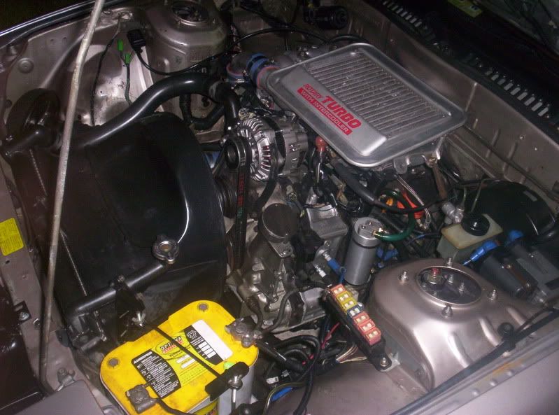
i got the same one , I took the middle box/nipple thing and threaded it into the top and then put a breather on it. And mounted it with the included L bracket onto the battery trey. Good setup if you have an electric fan, so then you have room and not soo obvious appearance.


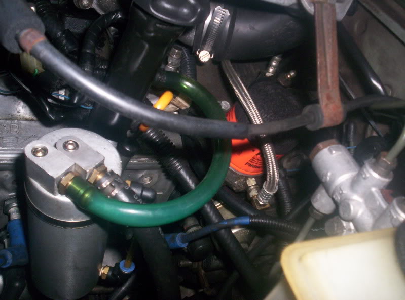
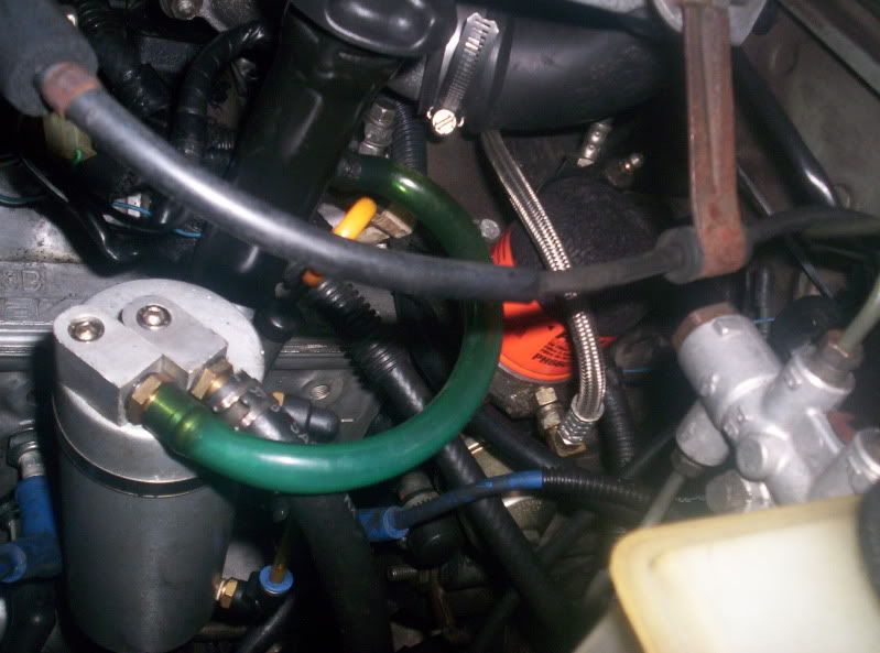
Plumb it like that, use the included tube adapter piece *whatever its called* as a cap on that hose, then just route the can to the fitting from the fitting on the oil fill.
Plumb it like that, use the included tube adapter piece *whatever its called* as a cap on that hose, then just route the can to the fitting from the fitting on the oil fill.
Trending Topics
So the stock hose that goes into the filler neck now I pull off and cap off? and put a hose going from the filler neck to the catch can? and the other nipple on the catch can I can just leave the way it is right? Do I have this right?
Joined: Feb 2001
Posts: 29,798
Likes: 128
From: London, Ontario, Canada
Much of the setup here is wrong.
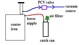
The proper way to connect a catch can is to run the lower nipple on the center iron to the catch can. Then have the top connection of the catch can draw air from a little filter (standalone) or from the TID (stock ECU). The nipple in the filler neck then gets connected to a vacuum port on the intake through a PCV valve.
This preserves the proper fresh air flow through the crankcase and prevents moisture buildup.
Card-carrying Rotorhead
Joined: May 2006
Posts: 457
Likes: 0
From: Quebec
Much of the setup here is wrong.
The proper way to connect a catch can is to run the lower nipple on the center iron to the catch can. Then have the top connection of the catch can draw air from a little filter (standalone) or from the TID (stock ECU). The nipple in the filler neck then gets connected to a vacuum port on the intake through a PCV valve.
This preserves the proper fresh air flow through the crankcase and prevents moisture buildup.
Ok so the stock hose thats on the filler neck we dont touch right? and the lower nipple on the center iron gets connected to the catch can. So what happenes to the hose that is connected to the center iron on a stock setup? Or is there nothing hooked up to it to begin with? I dont have my car with me or I would check it.
Joined: Feb 2001
Posts: 29,798
Likes: 128
From: London, Ontario, Canada
The bottom nipple goes to a passage that leads to the center of the engine. The top nipple goes to the filler neck.
The stock system draws air into the bottom nipple, through the crankcase, then out through the top nipple. This circulates air inside the engine and cleans out all that crap that PCV systems are designed to clean; moisture, combustion blowby, vapors, etc. This is now the stock system works and this is how a catch can should be set up.
The stock system draws air into the bottom nipple, through the crankcase, then out through the top nipple. This circulates air inside the engine and cleans out all that crap that PCV systems are designed to clean; moisture, combustion blowby, vapors, etc. This is now the stock system works and this is how a catch can should be set up.
There is no need to run vacuum through the catch can. The only advantage to doing this would be longer intervals in draining the can, the primary job of the setup is to vent crankcase pressure. I feel it adds extra plumbing and increases the risk of vacuum leaks but if the car is daily driven it would be worthwhile.
Also the whole point of running a catch can is to keep the dirty oil/water mixture from being sent to the engine which causes carbon buildup and degrades the fuel octane level (more so than it already is with the OMP).
Also the whole point of running a catch can is to keep the dirty oil/water mixture from being sent to the engine which causes carbon buildup and degrades the fuel octane level (more so than it already is with the OMP).
What crankcase pressure? This isn't a piston engine. Most of these old rotaries are so worn out and have so much blow by the oil is quickly contaminated with fuel. I wouldn't even bother with a catch can. Just run 5/8" fuel line from the center iron nipple to a soda bottle and wrap a rag and zip tie around the neck to serve as an air filter.