How To: Single Turbo Harness
 12-24-09, 06:06 AM
#1
Turd Ferguson
Thread Starter
iTrader: (1)
Join Date: Jul 2006
Location: Sherman Oaks, California
Posts: 2,047
Likes: 0
Received 1 Like
on
1 Post
How To: Single Turbo Harness
Before you begin, familiarize yourself with the harness. Know what plugs you want to remove. Then read the forums and determine if you still want to remove them. Finally, I take no responsibility if you mess up your harness. You do the below at your own risk and if there are any errors in my instructions it is up to you to sort them out before you start.
Tools/Items You’ll Need:
A very small screwdriver
Wire Cutters
Soldering Iron
Solder
Heat Shrink Wrap
Needle-Nose Pliers
A variety of colored wire in gauge near to that of the harness wire
Electrical Tape
Box Cutter/Razor Blade
Wire Loom Protectors
Engine Harness
How to: Single Turbo Harness
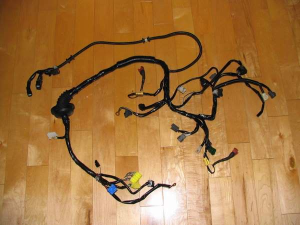
1. Lay out the harness on a flat surface.
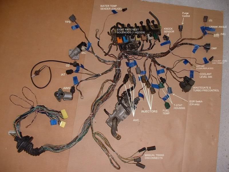
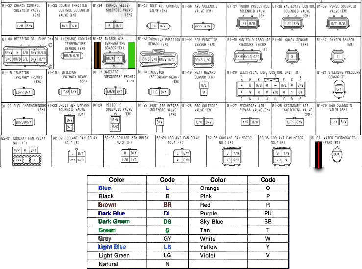
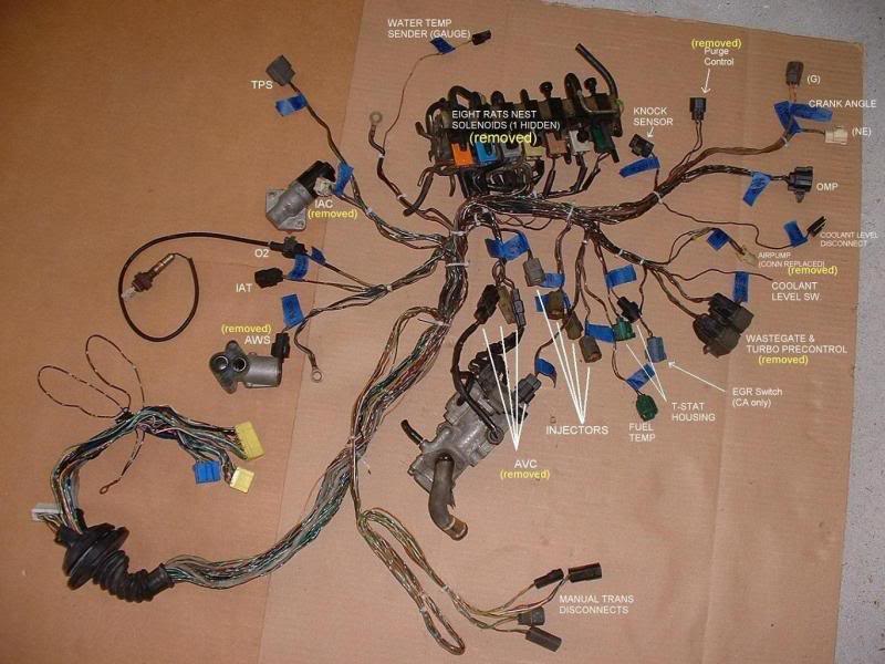
2. Label all the plugs with tape and marker. It is especially important to identify the following plugs as they will be removed and/or modified: AWS, Purge, AVSx4, Wastegate, Pre-control, EGR, IAC/ISC, Air Pump, Rats nest x 8. Use the below diagrams. *A NOTE HERE: the automatic transmission harness is different than the pictured harness below; however, all essential plugs that you will be removing/modifying remain the same. If you can’t figure out what the plug is and have located all of the plugs on the diagram then don’t worry about it.
3. Carefully remove electrical tape and loom protection. Go slow if this is an older harness or if using a sharp blade. I used a box cutter and a pair of scissors to remove all piece of tape holding the loom together. Be especially careful not to nick the wires.
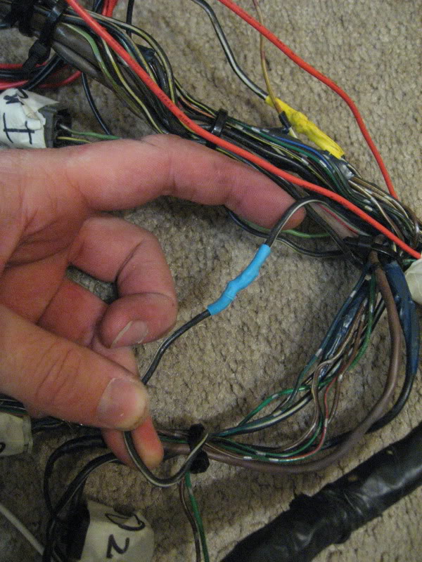
4. Zip tie the loom at the various points of their splitting. You can see the white zip-ties on the first picture. This helps keep the loom from knotting or from becoming a mental overload.
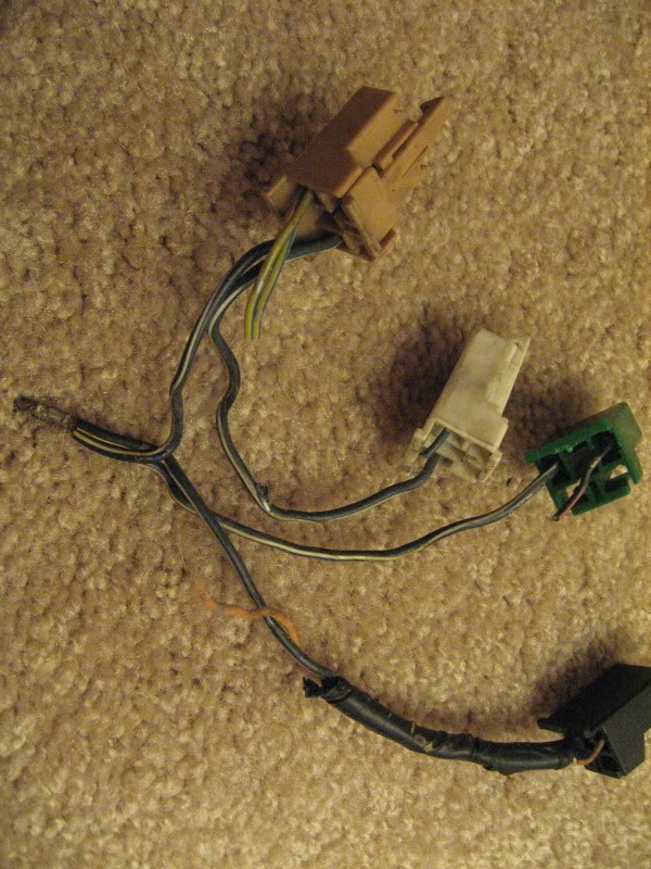
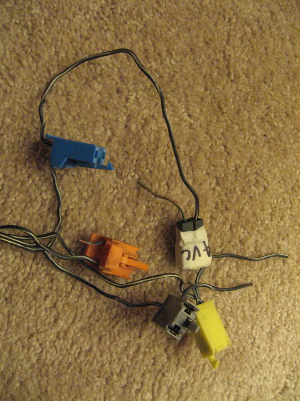
5. Let’s get the nest first, locate the Grey plug within the rat’s nest. You will see two black wires with a white stripe. This wire runs throughout the rats nest and is a ground. Cut all of the colored wires attached to the rat nest’s plugs. Leave the black/white wires in place.
6. Here notice that there are actually 2 clusters within the rat nest. The first cluster is connected with the black/white wire are the Blue, Grey, Yellow, Orange and Black AVC plug. The second clusters is the Green, Brown and White, Black plugs. Trace the black/White wire from the grey connector to the trunk of the loom. You will find a metal junction that merges this cluster’s ground to the main harness. Cut this wire just below the metal junction so that the cluster can be removed. Repeat this process for the other cluster (Brown, Green, etc..).
7. Locate your other plugs and cut their wires. On my harness I cut the following: AWS, Purge, AVSx4, Wastegate, Pre-control, EGR, AirPump, Rats nest x 7. You will start to notice that most of the plugs have a black/white ground wire running to them. I DID NOT REMOVE MY IAC/ISC.
8. Pull the colored wires that you’ve cut out of the loom. You’ll have a bunch.
9. The colored wires will run down to the connectors that plug into the ECU.
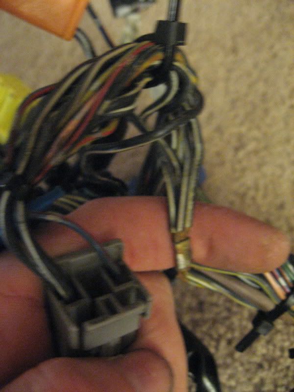
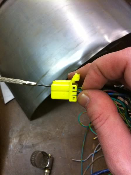
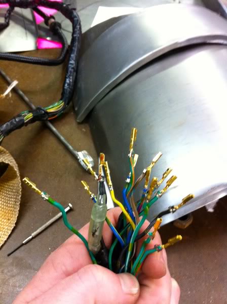
10. There’s probably many ways to de-pin the connectors. Here’s how I did it. On the yellow plugs the tops and bottom of the plug flips open. Look at the sides of the plugs and notice the small tabs. Carefully open the flip-tops of the plugs with a small screwdriver. I then take a pair of needle-nose pliers and grab the wire as close to the plug as possible with the pliers parallel to the plug. Next I rotate the pliers opposite direction from the plug and pull the pin out of the plug. See below.
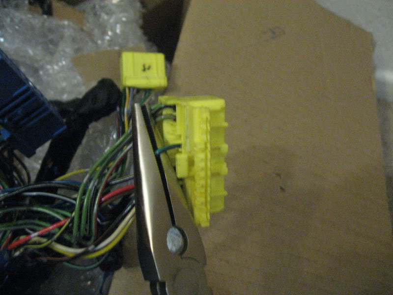
11. Take out all of the colored wires to the plugs you're removing and their pins.
Tools/Items You’ll Need:
A very small screwdriver
Wire Cutters
Soldering Iron
Solder
Heat Shrink Wrap
Needle-Nose Pliers
A variety of colored wire in gauge near to that of the harness wire
Electrical Tape
Box Cutter/Razor Blade
Wire Loom Protectors
Engine Harness
How to: Single Turbo Harness
1. Lay out the harness on a flat surface.
2. Label all the plugs with tape and marker. It is especially important to identify the following plugs as they will be removed and/or modified: AWS, Purge, AVSx4, Wastegate, Pre-control, EGR, IAC/ISC, Air Pump, Rats nest x 8. Use the below diagrams. *A NOTE HERE: the automatic transmission harness is different than the pictured harness below; however, all essential plugs that you will be removing/modifying remain the same. If you can’t figure out what the plug is and have located all of the plugs on the diagram then don’t worry about it.
3. Carefully remove electrical tape and loom protection. Go slow if this is an older harness or if using a sharp blade. I used a box cutter and a pair of scissors to remove all piece of tape holding the loom together. Be especially careful not to nick the wires.
4. Zip tie the loom at the various points of their splitting. You can see the white zip-ties on the first picture. This helps keep the loom from knotting or from becoming a mental overload.
5. Let’s get the nest first, locate the Grey plug within the rat’s nest. You will see two black wires with a white stripe. This wire runs throughout the rats nest and is a ground. Cut all of the colored wires attached to the rat nest’s plugs. Leave the black/white wires in place.
6. Here notice that there are actually 2 clusters within the rat nest. The first cluster is connected with the black/white wire are the Blue, Grey, Yellow, Orange and Black AVC plug. The second clusters is the Green, Brown and White, Black plugs. Trace the black/White wire from the grey connector to the trunk of the loom. You will find a metal junction that merges this cluster’s ground to the main harness. Cut this wire just below the metal junction so that the cluster can be removed. Repeat this process for the other cluster (Brown, Green, etc..).
7. Locate your other plugs and cut their wires. On my harness I cut the following: AWS, Purge, AVSx4, Wastegate, Pre-control, EGR, AirPump, Rats nest x 7. You will start to notice that most of the plugs have a black/white ground wire running to them. I DID NOT REMOVE MY IAC/ISC.
8. Pull the colored wires that you’ve cut out of the loom. You’ll have a bunch.
9. The colored wires will run down to the connectors that plug into the ECU.
10. There’s probably many ways to de-pin the connectors. Here’s how I did it. On the yellow plugs the tops and bottom of the plug flips open. Look at the sides of the plugs and notice the small tabs. Carefully open the flip-tops of the plugs with a small screwdriver. I then take a pair of needle-nose pliers and grab the wire as close to the plug as possible with the pliers parallel to the plug. Next I rotate the pliers opposite direction from the plug and pull the pin out of the plug. See below.
11. Take out all of the colored wires to the plugs you're removing and their pins.
 12-24-09, 06:07 AM
#2
Turd Ferguson
Thread Starter
iTrader: (1)
Join Date: Jul 2006
Location: Sherman Oaks, California
Posts: 2,047
Likes: 0
Received 1 Like
on
1 Post
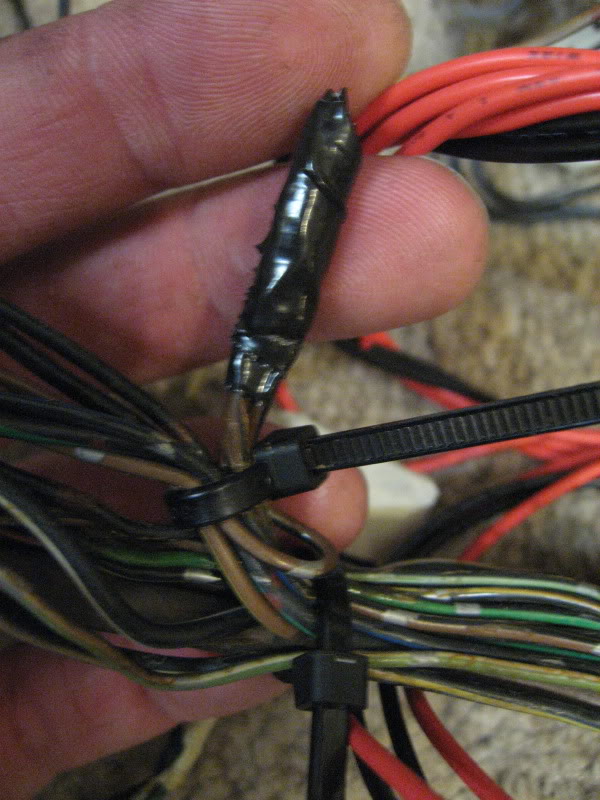
12. Now for grounds. The grounds will all trace back to a metal juncture point. You can clip them above the metal junction or solder them all together. I cut all of mine with the exception of 1 near the IAC/ISC plug. Step 13.
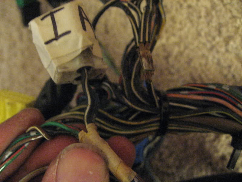
13. Because you cut out the rat net, the IAC/ISC plug is now improperly grounded and will not function. To resolve this you must connect the cut ground wire from the IAC/ISC plug and solder it with one of the grounds connected to the main wiring loom.
14. A word about the EGR. It does not have a black/white ground. Instead it has a brown wire and a blue/aqua wire. The blue/aqua wire will run to one of the yellow plugs at the start of the loom. You’ll de-pin it as normal. The brown wire will run to a metal junction of other brown wires. Cut the brown wire from the EGR as close to the metal junction as possible without disturbing the other wires on the other side of the metal junction and then wrap the junction back up.
14. At this point you are essentially done with the exception of taping everything up. I, however, went one step further per badddrx7’s advice and added additional BLANK wires back into the loom should I require wires for future gauges or electrical needs.
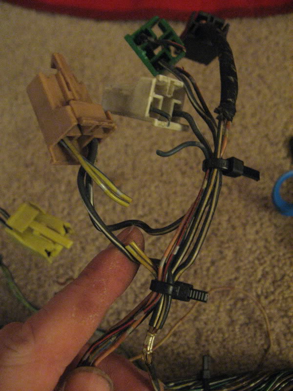
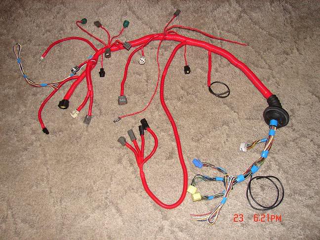
15. To do this, take several different colored wires and run them up the length of the wiring harness. In the picture below you can see them as the multi-colored wires at either end that appear looped around. This will give you extra wires should you need them in the future and you will not have to open up the harness. Be sure to give yourself plenty of length as you never know where you might allocate them in the future.
16. Now it’s time to put it all back together. Get out your best electrical tape (I use 3M *Scotch� Super 33+™ Vinyl Electrical Tape) and wire loom protectors. Some options:
Russell Performance “Russell Wrap-It”
http://www.summitracing.com/search/?...0wrap-it&dds=1
Electric-Life “Electric-Life Accordion-Style Wire Looms”
http://www.summitracing.com/parts/ELI-5050-10-099/
You can find the accordion wire loom at local Advance Auto, NAPA, AutoZone or PepBoys.
17. Be sure to tape up any of the exposed metal junction points first. Then move to the areas near the zip-ties (and remove the ties). Then to any of the wires that run near one another together to plugs. And so forth.
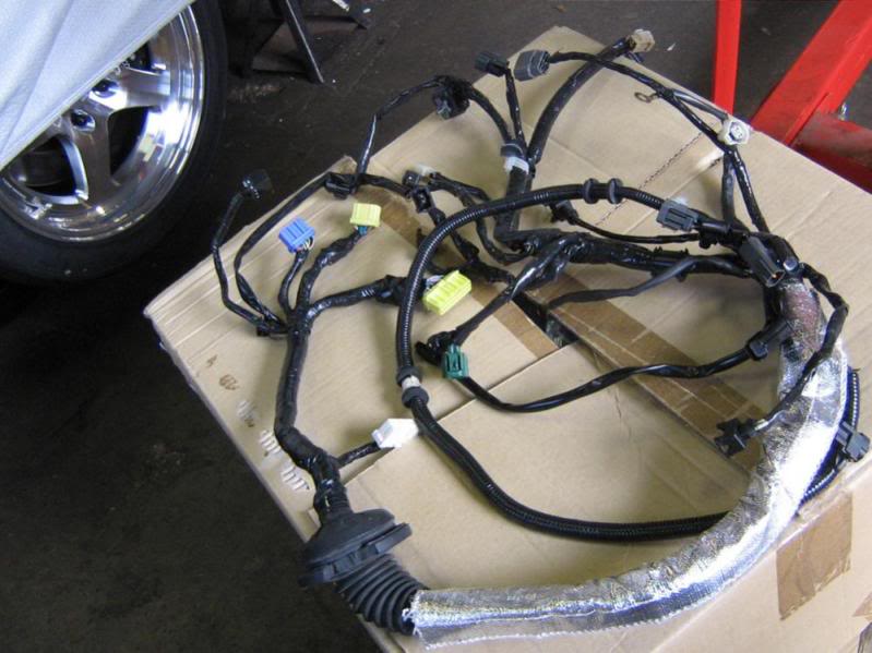
Here are some pictures of others' completed looms:
13. Because you cut out the rat net, the IAC/ISC plug is now improperly grounded and will not function. To resolve this you must connect the cut ground wire from the IAC/ISC plug and solder it with one of the grounds connected to the main wiring loom.
14. A word about the EGR. It does not have a black/white ground. Instead it has a brown wire and a blue/aqua wire. The blue/aqua wire will run to one of the yellow plugs at the start of the loom. You’ll de-pin it as normal. The brown wire will run to a metal junction of other brown wires. Cut the brown wire from the EGR as close to the metal junction as possible without disturbing the other wires on the other side of the metal junction and then wrap the junction back up.
14. At this point you are essentially done with the exception of taping everything up. I, however, went one step further per badddrx7’s advice and added additional BLANK wires back into the loom should I require wires for future gauges or electrical needs.
15. To do this, take several different colored wires and run them up the length of the wiring harness. In the picture below you can see them as the multi-colored wires at either end that appear looped around. This will give you extra wires should you need them in the future and you will not have to open up the harness. Be sure to give yourself plenty of length as you never know where you might allocate them in the future.
16. Now it’s time to put it all back together. Get out your best electrical tape (I use 3M *Scotch� Super 33+™ Vinyl Electrical Tape) and wire loom protectors. Some options:
Russell Performance “Russell Wrap-It”
http://www.summitracing.com/search/?...0wrap-it&dds=1
Electric-Life “Electric-Life Accordion-Style Wire Looms”
http://www.summitracing.com/parts/ELI-5050-10-099/
You can find the accordion wire loom at local Advance Auto, NAPA, AutoZone or PepBoys.
17. Be sure to tape up any of the exposed metal junction points first. Then move to the areas near the zip-ties (and remove the ties). Then to any of the wires that run near one another together to plugs. And so forth.
Here are some pictures of others' completed looms:
12-24-09, 06:14 AM
#3
Turd Ferguson
Thread Starter
iTrader: (1)
Join Date: Jul 2006
Location: Sherman Oaks, California
Posts: 2,047
Likes: 0
Received 1 Like
on
1 Post
I should also add that if you have a fast reacting IAT that you've been waiting to install. this is the time. Cut the IAT plug and solder your new IAT onto the harness per your IAT vendor's instruction.

Trending Topics
12-24-09, 11:26 AM
#8
Canadiana... Eh?
iTrader: (2)
Join Date: Aug 2009
Location: Canada
Posts: 537
Likes: 0
Received 0 Likes
on
0 Posts
wow would this have helped me out when I did my harness.
Keep in mind those of you who are planning to do this... do a really good "look over" of all the other wires while you're in there. I found quite a few cracked/splitting wires that needed to be repaired. This outlines what you need to remove and how to do it, but spend an extra hour looking everything over from ECU to clips. It will save headaches when you re-install it and it doesn't work. Especially after wrapping it in tape !
Keep in mind those of you who are planning to do this... do a really good "look over" of all the other wires while you're in there. I found quite a few cracked/splitting wires that needed to be repaired. This outlines what you need to remove and how to do it, but spend an extra hour looking everything over from ECU to clips. It will save headaches when you re-install it and it doesn't work. Especially after wrapping it in tape !
12-24-09, 04:59 PM
#9
Unhealthy Obsession
iTrader: (3)

Join Date: May 2006
Location: NNJ
Posts: 482
Likes: 0
Received 0 Likes
on
0 Posts
Just what i was looking for. Ill post my question here.
So a bare minimum harness would be as follow:
- Tps
- Omp
- Iat
- Water Temp Sender Gauge
- Coolant level Switch
- Knock sensor disconnect / coolant level disconnect (which does not pin into any connectors)
- Tsat housing X2
- Injectors X4
- Crank angle sensors X2
- Trans. Disconnects
Now there are 3 grounds in all I need help in direction with all three.
The ground near the ecu connectors made its way apart from one side can some diagram how this needs to be re soldered up?
The two other grounds bridge together to three wires that lead back to the white connector plug and the other two to the yellow connector plug. Should i leave these in the harness or can they be taken out?
Last edited by rx927; 12-24-09 at 05:00 PM. Reason: Forgot trans disconnects

 awesome
12-25-09, 01:05 AM
awesome
12-25-09, 01:05 AM
#12
Turd Ferguson
Thread Starter
iTrader: (1)
Join Date: Jul 2006
Location: Sherman Oaks, California
Posts: 2,047
Likes: 0
Received 1 Like
on
1 Post
 12-26-09, 08:20 PM
#13
Harness w/o plugs that are not needed.
I was considering fabricating a complete harness, just like OEM, but w/o the plugs for all the stuff that gets eliminated. No butt connectors, tape, etc.. I mean brand new but w/o the junk. I will have to try it on my car first of course. If there were such a harness available does anyone think that it could be something others would want?
12-26-09, 11:25 PM
#15
Jonny. It definately applies to single turbo cars with power fcs. I mean, you can leave those lines in, the would just clutter up the engine bay. This is just like unplugging them, except more permanent.
I just did this. Thanks grimple for the guidance.
I just did this. Thanks grimple for the guidance.
12-27-09, 12:48 AM
#16
Derwin
iTrader: (2)
Join Date: Apr 2005
Location: MTL, QC
Posts: 2,888
Likes: 0
Received 0 Likes
on
0 Posts
I was considering fabricating a complete harness, just like OEM, but w/o the plugs for all the stuff that gets eliminated. No butt connectors, tape, etc.. I mean brand new but w/o the junk. I will have to try it on my car first of course. If there were such a harness available does anyone think that it could be something others would want?
12-27-09, 05:08 PM
#18
I see one of my red loomed single turbo harnesses in there. Good write up. For whatever application you are running, taking your engine harness apart and cleaning it up will yield better performance. Hard baked wires will not deliver a good signal and shielded wires need just that - good shielding.
LAter
LAter
12-28-09, 02:05 AM
#21
Canadiana... Eh?
iTrader: (2)
Join Date: Aug 2009
Location: Canada
Posts: 537
Likes: 0
Received 0 Likes
on
0 Posts
No.. I didn't go that in depth. My harness was fairly low KM. I visually went over and "bent around" every wire to check for cracks. I also looked at every clip where the wires attach, and if there was wire showing I replaced it and for some threw some silicone over the wire to seal it from moisture.
01-27-10, 08:39 AM
#23
Senior Member

Join Date: Nov 2007
Location: Warwickshire, UK
Posts: 251
Likes: 0
Received 0 Likes
on
0 Posts
Sorry to bump a hugely old post, but wuick questyion about the ever elusive earth wire for the ICV.
On mine (JDM car) it seems to earth to a pin on the blue connector - I'm guessing I don't need to splice it to an additional earth as well as this?
Cheers guys, and sorry for the thread revival.
Ace thread BTW, so useful.
On mine (JDM car) it seems to earth to a pin on the blue connector - I'm guessing I don't need to splice it to an additional earth as well as this?
Cheers guys, and sorry for the thread revival.
Ace thread BTW, so useful.
03-26-11, 07:15 PM
#25
Full Member
iTrader: (2)
Join Date: Jan 2003
Location: Springfield MO
Posts: 216
Likes: 0
Received 0 Likes
on
0 Posts
I wanted to add another method of de-pinning the connectors that proved to be much simpler than the aforementioned needle nose pry and pull method. I figured this was the best place to post this since a lot of people reference it for doing their single turbo harness conversion.
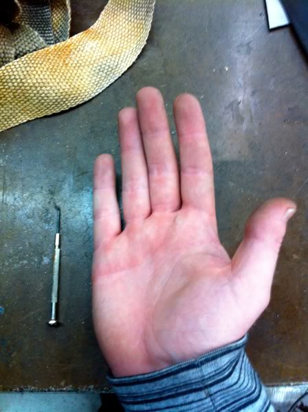
First the tools you'll need: A eyeglass screw driver and one of your hands ;-)
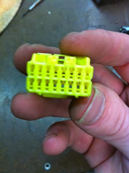
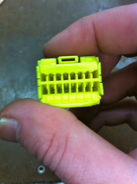
Then with the small screwdriver lift open the flip tops that hold in the wires. You'll see on the sides; small little tabs holding the flip tops down like mentioned earlier.
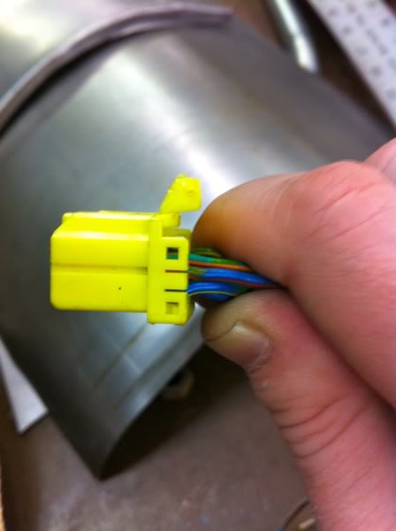
Next, look in the face of the connector and you'll see in the big hole a small little tab.
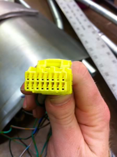
Take your small screw driver and insert at an angle applying pressure to the bottom of the tab inside of the connector and lift the tab up. Basically you're prying up the yellow tab. As you are holding up the tab take your spare hand holding the wire and pull back allowing the pin to slide right out.
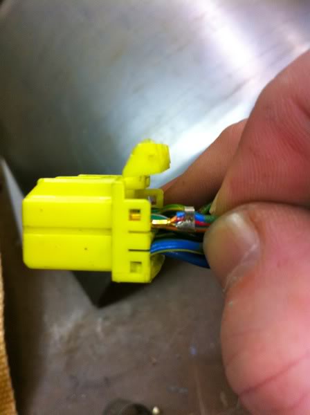
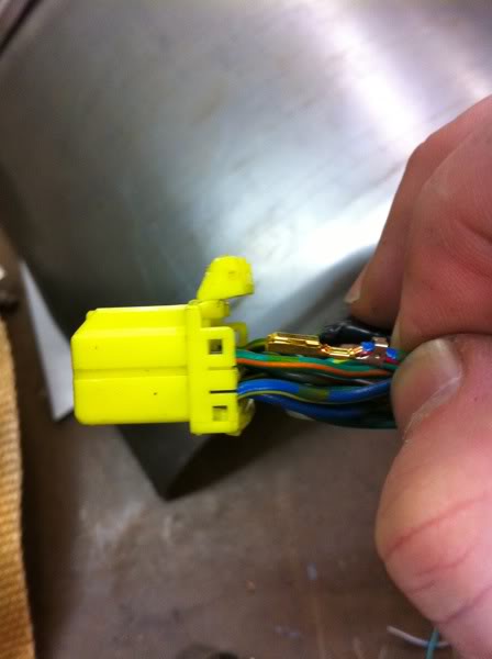
Voila! Done and you have a clean uninstall! Look at all those re-usable wires and pins!
Also re-usable are the connectors and they are really hard to come by. Oh yeah these yellow ones are exactly the same on a FC as on a FD.
First the tools you'll need: A eyeglass screw driver and one of your hands ;-)
Then with the small screwdriver lift open the flip tops that hold in the wires. You'll see on the sides; small little tabs holding the flip tops down like mentioned earlier.
Next, look in the face of the connector and you'll see in the big hole a small little tab.
Take your small screw driver and insert at an angle applying pressure to the bottom of the tab inside of the connector and lift the tab up. Basically you're prying up the yellow tab. As you are holding up the tab take your spare hand holding the wire and pull back allowing the pin to slide right out.
Voila! Done and you have a clean uninstall! Look at all those re-usable wires and pins!
Also re-usable are the connectors and they are really hard to come by. Oh yeah these yellow ones are exactly the same on a FC as on a FD.