Rtek New target AFR tables
 03-03-10, 02:35 PM
#1
New target AFR tables
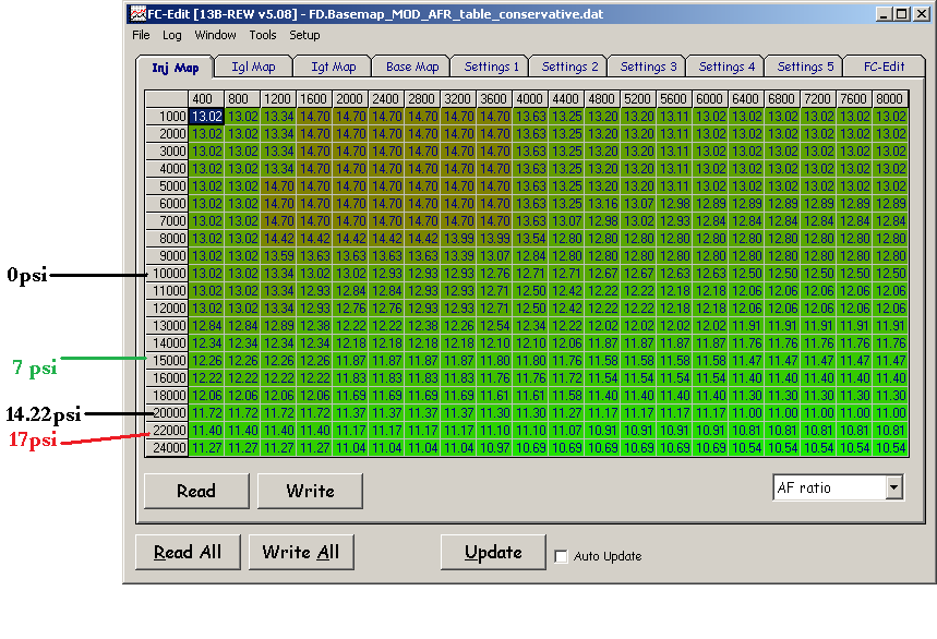
I have already covered timing maps in this thread: https://www.rx7club.com/rtek-forum-168/new-boost-based-timing-maps-885556/ . Now I want to discuss target AFR ranges and AFR target table strategies. Just like that thread, I've divided up the fuel maps into "conservative," "moderate," and "somwhat aggressive." I made these target AFR maps with my Power FC software because it is easy to manipulate quickly. I know the breakpoints aren't the same as the fuel correction map in the Rtek, but I have labeled the boost axis to make it easier to read. The boost cells are in Kg/Cm^2 of absolute pressure where 10000 = atmospheric pressure and 20000 is 14.22psi boost.
On to the maps. Now there are two tuning principles to consider:
1) the numbers--the basic range of target AFR. Figure your AFR is always going to fluctuate within a range of +/- .3 points of AFR. The number ranges I am using here are based on personal experience with multiple setups but also certain accepted "rules of thumb" among rotary tuners, such as don't run leaner than 12:1 under higher boost levels with only normal pump fuel.
2) the shape of the curve--how target AFR changes with rpm and boost. You have to think three dimensionally here, just like with the timing maps. In all three of these maps a different shaped fuel curve is utilized. As boost increases, you can either richen up the AFR or keep it the same. As RPM increases, you can richen it up to reduce the chance of detonation at peak combustion pressure (peak torque) area. You can lean it out in less detonation prone areas (before and after the peak torque range). You can also keep it unchanged (flat). All three strategies are illustrated here.
The biggest thing you'll notice with the conservative map is that AFR's continue to get richer as rpm and boost increase. You'll see this on a lot of OEM maps. This richening is not necessary but I want to illustrate that it is one way of doing things.
Moderate: Along the rpm axis, the AFR curve flattens once you get near the peak torque area and stays flat until redline. This is a common strategy employed by tuners.

Somewhat aggressive: just like the moderate map, the AFR curve richens and flattens once you get near the peak torque area. But then the AFR leans out a bit once you get past peak torque. Also, as you go down the boost axis the AFR "flattens" out when you get to about 8-9psi. It stops getting richer as boost goes up.

For those of you who have looked at my timing maps: you don't always have to use a "conservative" timing with "conservative" AFR targets--not necessarily anyway. For example, if you have 8.5:1 rotors, a good FMIC, and 93 octane the "somewhat aggressive" fuel map could work with the "moderate" timing map. Of you could use "conservative" fuel with "moderate" timing. For those of you running stock intercoolers, I wouldn't recommend anything leaner than the "moderate" fuel map. And even then I would be careful with timing. If you have 91 octane along with the stock TMIC I would stay with the "conservative" fuel targets, especially if you have 9.0:1 or higher compression.
I personally run "somewhat aggressive" AFR targets with timing closer to the "conservative" map posted in the other thread. That's at about 16.5psi with FMIC, 8.5:1 compression, T04R turbo. Again I don't take any responsibility for anything that happens as a result of anyone taking my advice or using anything I've provided.
On to the maps. Now there are two tuning principles to consider:
1) the numbers--the basic range of target AFR. Figure your AFR is always going to fluctuate within a range of +/- .3 points of AFR. The number ranges I am using here are based on personal experience with multiple setups but also certain accepted "rules of thumb" among rotary tuners, such as don't run leaner than 12:1 under higher boost levels with only normal pump fuel.
2) the shape of the curve--how target AFR changes with rpm and boost. You have to think three dimensionally here, just like with the timing maps. In all three of these maps a different shaped fuel curve is utilized. As boost increases, you can either richen up the AFR or keep it the same. As RPM increases, you can richen it up to reduce the chance of detonation at peak combustion pressure (peak torque) area. You can lean it out in less detonation prone areas (before and after the peak torque range). You can also keep it unchanged (flat). All three strategies are illustrated here.
The biggest thing you'll notice with the conservative map is that AFR's continue to get richer as rpm and boost increase. You'll see this on a lot of OEM maps. This richening is not necessary but I want to illustrate that it is one way of doing things.
Moderate: Along the rpm axis, the AFR curve flattens once you get near the peak torque area and stays flat until redline. This is a common strategy employed by tuners.
Somewhat aggressive: just like the moderate map, the AFR curve richens and flattens once you get near the peak torque area. But then the AFR leans out a bit once you get past peak torque. Also, as you go down the boost axis the AFR "flattens" out when you get to about 8-9psi. It stops getting richer as boost goes up.
For those of you who have looked at my timing maps: you don't always have to use a "conservative" timing with "conservative" AFR targets--not necessarily anyway. For example, if you have 8.5:1 rotors, a good FMIC, and 93 octane the "somewhat aggressive" fuel map could work with the "moderate" timing map. Of you could use "conservative" fuel with "moderate" timing. For those of you running stock intercoolers, I wouldn't recommend anything leaner than the "moderate" fuel map. And even then I would be careful with timing. If you have 91 octane along with the stock TMIC I would stay with the "conservative" fuel targets, especially if you have 9.0:1 or higher compression.
I personally run "somewhat aggressive" AFR targets with timing closer to the "conservative" map posted in the other thread. That's at about 16.5psi with FMIC, 8.5:1 compression, T04R turbo. Again I don't take any responsibility for anything that happens as a result of anyone taking my advice or using anything I've provided.
 03-03-10, 05:48 PM
#2
404** File not Found
iTrader: (6)

Join Date: Feb 2008
Location: houston
Posts: 399
Likes: 0
Received 0 Likes
on
0 Posts
i appreciate these. i have tuned on some FWD boingers and a termie my friend had, but this is kind of alien territory to me. this helps me a lot more to go on to get a base tune. still going to have someone look over the tune for me though.
07-20-10, 11:20 PM
#3
bumping this thread per a question via PM about general advice for what AFR's to go for.
One thing to keep in mind: open vs closed loop control logic. The factory ECU has certain criteria to determine whether the O2 sensor feedback should be used. When the O2 feedback is being used the AFR will fluctuate between 14:1 and 15:1 pretty consistently. Usually that's during cruising under about 4000rpm (before secondary injectors come online) with steady throttle. Sometimes you will see the vehicle stay in closed loop at part throttle boost when cruising. That's not necessarily cause for alarm.
I don't know the exact logic that the factory computer uses to switch between open loop (o2 sensor ignored) and closed loop (ECU tries to keep between 14:1 and 15:1) when the engine isn't idling or decelerating. From what I've seen on other cars, especially Subarus, the basic factors are:
1) throttle position -- if TPS % exceeds some level, the engine will go into open loop
2) load -- load is a function of airflow voltage divided by rpm. So if the AFM signal gets high enough at a given engine rpm, the ECU will go into open loop operation and enrich the mixture
3) rpm -- the stock ECU seems to go into open loop once the secondary injectors come online, at least from what I've seen.
4) delay counter -- I'm not sure if the Rtek/stock ECU has this. Basically after some of the above conditions have been met, the delay counter waits a certain number of milliseconds before going open loop. This keeps the ECU from immediately dumping in fuel when it may not necessary.
For an explanation of open/closed loop transition on WRX/STi, see
http://www.romraider.com/forum/viewt...hp?f=25&t=1603
 07-21-10, 06:27 PM
#7
bumping this thread per a question via PM about general advice for what AFR's to go for.
One thing to keep in mind: open vs closed loop control logic. The factory ECU has certain criteria to determine whether the O2 sensor feedback should be used. When the O2 feedback is being used the AFR will fluctuate between 14:1 and 15:1 pretty consistently. Usually that's during cruising under about 4000rpm (before secondary injectors come online) with steady throttle. Sometimes you will see the vehicle stay in closed loop at part throttle boost when cruising. That's not necessarily cause for alarm.
I don't know the exact logic that the factory computer uses to switch between open loop (o2 sensor ignored) and closed loop (ECU tries to keep between 14:1 and 15:1) when the engine isn't idling or decelerating. From what I've seen on other cars, especially Subarus, the basic factors are:
1) throttle position -- if TPS % exceeds some level, the engine will go into open loop
2) load -- load is a function of airflow voltage divided by rpm. So if the AFM signal gets high enough at a given engine rpm, the ECU will go into open loop operation and enrich the mixture
3) rpm -- the stock ECU seems to go into open loop once the secondary injectors come online, at least from what I've seen.
4) delay counter -- I'm not sure if the Rtek/stock ECU has this. Basically after some of the above conditions have been met, the delay counter waits a certain number of milliseconds before going open loop. This keeps the ECU from immediately dumping in fuel when it may not necessary.
For an explanation of open/closed loop transition on WRX/STi, see
http://www.romraider.com/forum/viewt...hp?f=25&t=1603
One thing to keep in mind: open vs closed loop control logic. The factory ECU has certain criteria to determine whether the O2 sensor feedback should be used. When the O2 feedback is being used the AFR will fluctuate between 14:1 and 15:1 pretty consistently. Usually that's during cruising under about 4000rpm (before secondary injectors come online) with steady throttle. Sometimes you will see the vehicle stay in closed loop at part throttle boost when cruising. That's not necessarily cause for alarm.
I don't know the exact logic that the factory computer uses to switch between open loop (o2 sensor ignored) and closed loop (ECU tries to keep between 14:1 and 15:1) when the engine isn't idling or decelerating. From what I've seen on other cars, especially Subarus, the basic factors are:
1) throttle position -- if TPS % exceeds some level, the engine will go into open loop
2) load -- load is a function of airflow voltage divided by rpm. So if the AFM signal gets high enough at a given engine rpm, the ECU will go into open loop operation and enrich the mixture
3) rpm -- the stock ECU seems to go into open loop once the secondary injectors come online, at least from what I've seen.
4) delay counter -- I'm not sure if the Rtek/stock ECU has this. Basically after some of the above conditions have been met, the delay counter waits a certain number of milliseconds before going open loop. This keeps the ECU from immediately dumping in fuel when it may not necessary.
For an explanation of open/closed loop transition on WRX/STi, see
http://www.romraider.com/forum/viewt...hp?f=25&t=1603
i once had an issue with running lean while going into closed loop. i'm pretty sure the ecu holds a long term fuel trim for when in closed loop... like most modern cars. some cars have it per cyclinder. it would be cool to have it per chamber or even remember which face of the rotors, like f1 f2 f3 and rear r1 r2 r3, but i think that's dreaming.
Trending Topics
07-22-10, 01:00 PM
#8
There are no long or short term fuel trims, at least not in the traditional sense that you would find with OBD II or late OBD I cars. Even the Series 6 FD doesn't have them (maybe the later 16 bit ECU's did). There are no mentions in the service manuals of trims and the people who have done disassembly haven't found anything.
07-22-10, 02:36 PM
#9
i do my best not to compare our rotards to any piston engine or newer car. everything always seems to be the oppasite, often during the day my boss will say "all cars have ****, or no car has a ****. and my responce 99 percent of the time..."well, my rotary does"( or doesn't). Even the non rotary specific stuff.
like the IAT sensor being effected by a warm engine. in the ASE test you're supposed to KNOW that the IAT sensor is in a plastic intake, therefore doesnt not read diffrently due to hot or cold intake manifolds.. but no, in rx-7s, it's in the metal.
like the IAT sensor being effected by a warm engine. in the ASE test you're supposed to KNOW that the IAT sensor is in a plastic intake, therefore doesnt not read diffrently due to hot or cold intake manifolds.. but no, in rx-7s, it's in the metal.
07-22-10, 03:21 PM
#10
i do my best not to compare our rotards to any piston engine or newer car. everything always seems to be the oppasite, often during the day my boss will say "all cars have ****, or no car has a ****. and my responce 99 percent of the time..."well, my rotary does"( or doesn't). Even the non rotary specific stuff.
like the IAT sensor being effected by a warm engine. in the ASE test you're supposed to KNOW that the IAT sensor is in a plastic intake, therefore doesnt not read diffrently due to hot or cold intake manifolds.. but no, in rx-7s, it's in the metal.
like the IAT sensor being effected by a warm engine. in the ASE test you're supposed to KNOW that the IAT sensor is in a plastic intake, therefore doesnt not read diffrently due to hot or cold intake manifolds.. but no, in rx-7s, it's in the metal.

It's in metal. So is the FC #2 IAT in the elbow, as you have already pointed out. The IAT sensor on the FD is on a primary intake runner in the manifold very much like the Honda pictured above. The FC and FD crank angle sensor has a similar signal to what a lot of other manufacturers were using (24-2 trigger wheel) at the time. The FC TPS is a lot like the button-style TPS/closed throttle sensor used on early Bosch systems. The FD TPS is a lot like the Honda TPS because it's a rotating, sliding potentiometer. The BAC valve in the FC and FD works like a Ford or Honda plunger style IACV. In fact the FD BAC/IACV looks just like the IACV on an 80s Ford 5.0 .
The EGR system on the FC and FD works a lot like early EGR systems (simple vacuum solenoid). The evaporative emissions system on the FC is similar to what you find on older Toyotas without a duty controlled EVAP solenoid. The list goes on. The ASE exam and your boss are focused on newer cars, that's all.
 08-05-10, 02:28 PM
#14
Moderator
iTrader: (3)
Join Date: Mar 2001
Location: https://www2.mazda.com/en/100th/
Posts: 30,761
Received 2,556 Likes
on
1,819 Posts
http://www.jimrothe.com/mazda/84_tra...raining_4b.pdf
if you scroll to page 32, there is a map that shows the different "zones", on this one the zones are TPS and RPM based (if you scroll back to about page 19-20, it explains the DC1, 2, and 3 tps sections).
so in the 1st gen the o2 feedback is not as rigidly fixed as the FD is.
the FC being in between both cars is in between both cars. i think the S4 is closer to the GSL-SE, and the s5 is closer to the FD
the FC has fixed RPM limits, 1500 and about 3500rpms. however it will pop out based on load, and seems to have a lot of latencies built in. if you're driving in closed loop @14.7:1 and quickly floor it and release the pedal back to where it was, it'll go rich, and stay there for a few seconds, before going back to closed loop.
the FD doesn't seem to have these latencies, it'll leave closed loop, and then go right back in.
as far as making adjustments to the fuel in the closed loop zone, i understand it the following way.
the ecu comes up with an injector duty #, and then it'll look at the o2 sensor and adjust it.
if you take the ecu #, and say subtract 2%, it'll inject its number -2% and then still correct for the o2 sensor to a point.
the opportunity is there where the map in the ecu gives you a richer than 14.7:1 mixture, and your change actually brings it closer to its target, its a small window though
08-10-10, 12:31 AM
#15
^ I have seen that document on the FB. Where are you getting the information for the FD and the FC? I know how my s4 turbo FC behaved on stock ECU, and I do recall it staying in closed loop under lower load boost and going open loop right around the time the secondaries came on.
08-10-10, 11:29 AM
#16
Quick thought.. what are your opinions on using a brake boosting method for slight fuel map tuning adjustments, ie, getting engine into the desired rpm band (say 5k) pressing the brakes and the gas until the car hits full boost (say 7 psi) then adjusting the duty cycle till they match what you want from the posted charts above? When i do my 2nd gear pulls on the street, even if I don't change anything between the pulls, my AFR's are not consistent which makes it hard to tune. I'm wondering if brake boosting will give me more consistent results?
Just a thought
Just a thought
08-10-10, 12:41 PM
#17
brake boosting is a lot like using a loading dyno. I used to screw around with brake boosting on stock turbo a lot actually. When it was cold outside I would brake boost to about 16psi. It was insanely abusive. Once I upgraded the turbo I found that i had to have my foot on the brakes hard to keep the car under control. It was just too abusive having the brake and the gas pedals of the way down.
If you want to be hardcore like this then I would rent time on a loading dyno, I think you're going to find that consistent brake boosting is hard to do on the street safely. Don't drive yourself nuts trying to get the AFR's perfect. Remember that the basic fuel calculation is based on airflow voltage while your fuel adjustment table is based on pressure sensor voltage. There is going to be enough variation in airflow and pressure through your various runs that repeatability isn't going to be perfect.
I'd just get it "good enough," whatever that ends up being I guess. You're going to pull your hair out otherwise. Now you may have an easier time doing that on a loading dyno, and you can certainly try brake boosting, but your AFR's will inevitably vary some. If you do look for a loading dyno, try finding a dynojet 224xlc or a 44xlc2. National Speed in Wilmington has a 44xlc2 and I had an opportunity to use it on an FD I was tuning down there. I didn't get a chance to use the "hold rpm" feature but you can set % load as well just to give it more of a road feel.
08-10-10, 05:58 PM
#18
Thanks! Yea, dyno time is going to be a must, I'm attempting to get it "good enough" so that my dyno experience is very brief and cheap(er). I'm trying to figure out ways to restore my torquey mid-range I used to have with the rtek 1.7. I could punch it at 4k and spin my fresh 225's tires even at 4-5psi. Now I have to side step the clutch to spin in the rain and it feels like i'm running a laggy front mount. I changed to a boost base timing map and input a mixture between your timing map and Solareon's, and I could feel a significant difference but still wasn't back to where I with the rtek 1.7. I've also tried leaning my AFR's into the 12's around 4-5k, butt dyno wasn't reading a considerable difference so I'm a little stumped.
08-15-10, 01:45 PM
#19
Somebody posted this (RotaryRocket ?):

I suppose that has a little more timing than the 1.7 did. Look through a log and compare the timing you are seeing to the stock values at the top. If you get on the dyno you can play around with the timing more on your own setup.
I suppose that has a little more timing than the 1.7 did. Look through a log and compare the timing you are seeing to the stock values at the top. If you get on the dyno you can play around with the timing more on your own setup.
08-26-10, 12:14 PM
#20
Moderator
iTrader: (3)
Join Date: Mar 2001
Location: https://www2.mazda.com/en/100th/
Posts: 30,761
Received 2,556 Likes
on
1,819 Posts
^ I have seen that document on the FB. Where are you getting the information for the FD and the FC? I know how my s4 turbo FC behaved on stock ECU, and I do recall it staying in closed loop under lower load boost and going open loop right around the time the secondaries came on.
the FC i've never seen a graph for, but having looked at the -SE and FD, and driven a few cars with an o2 sensor, you can see its not very different. the thing i noticed is that there are a lot more latencies, if you're cruising, floor it, and then let up to where you had it before, it'll pop into open loop, and stay there for a bit (5 seconds?) before finding closed loop again. the FD doesn't do that
the FC seems like its a little more flexible with its open loop/closed loop strategy. the FD is either 1psi or 3200rpm which ever comes first. i think the FD they did this because the turbo responds way faster
05-18-11, 07:12 AM
#21
Thanks arghx for all the info!
If you install an Electronic Boost Controller in the FC and use the Overboost/Scramble function that makes the turbo spool way faster than before, will there be any problems with the ECU trying to keep up adjusting mixtures?
Thanks!
If you install an Electronic Boost Controller in the FC and use the Overboost/Scramble function that makes the turbo spool way faster than before, will there be any problems with the ECU trying to keep up adjusting mixtures?
Thanks!
 04-25-17, 11:39 AM
#23
I want to bump this old thread to clarify something:
Conservative AFR table: Use this if you have a cat. You want it to be richest at high rpm/high boost to protect the cat. I mean you could still get away with the moderate table if you have a cat, but you are reducing the life of it and that could lead to failing an emissions test eventually.
Moderate AFR table: This is appropriate for most setups that don't have a cat.
Somewhat aggressive table: Try this if you have water injection to reduce knock and cool the turbo/cat.

Thread
Thread Starter
Forum
Replies
Last Post
edgars95rx7
Link Vi-PEC
0
10-01-15 01:59 PM

