solidworks project?
 06-06-07, 06:19 PM
#1
Full Member
Thread Starter

Join Date: Mar 2005
Location: So. Cal
Posts: 189
Likes: 0
Received 0 Likes
on
0 Posts
solidworks project?
hey. anyone have any solidworks project that they have that can send me in solidworks file? Could be anything, a rotary, suspension, clutch, lsd, etc. etc. anything would be fine. please send whatever you have if you have any. thanks!
my email is kevintsvu@yahoo.com
kevin
my email is kevintsvu@yahoo.com
kevin
 06-06-07, 09:45 PM
#3
Full Member
Thread Starter
Join Date: Mar 2005
Location: So. Cal
Posts: 189
Likes: 0
Received 0 Likes
on
0 Posts
im not going to rip off your design and machine it or anything. i just have a project that i have to do for solidworks for school. and it be nice if i get help. its totally up to you guys if you want to help out or if you dont mind sharing your solidworks project.
06-06-07, 10:37 PM
#4
All of mine are in Solid Edge... I have some of rotors, housings, and side plates.
I don't want to sounds like I am preaching but if it is for school you should probably get some good practice in... I played with solid edge for days on end before starting my project just designing pencils and the like, and assembling them got me used to the software.
Good Luck
I don't want to sounds like I am preaching but if it is for school you should probably get some good practice in... I played with solid edge for days on end before starting my project just designing pencils and the like, and assembling them got me used to the software.
Good Luck
06-07-07, 12:03 AM
#5
Full Member
Thread Starter
Join Date: Mar 2005
Location: So. Cal
Posts: 189
Likes: 0
Received 0 Likes
on
0 Posts
i know what you mean. im a mechanical engineer major and im just really press for time right now being that finals are coming up next week. and i have so many projects and papers due and on top of that finals to study for. just a little stressed on trying to get everything done and was hoping to get help. thanks though.
but anyways something like rotors and housings would be perfect but unfortunately i need them in solidworks. anyone else have any solidworks files?
but anyways something like rotors and housings would be perfect but unfortunately i need them in solidworks. anyone else have any solidworks files?
06-07-07, 10:52 AM
#6
Junior Member

Join Date: Jun 2007
Location: North Carolina
Posts: 6
Likes: 0
Received 0 Likes
on
0 Posts
I am making some rotary projects on s/w. I can help you get the shape.
Make a circle at any given radius, Snap to the upper or lower quadrant, make a circle to the center, now see where the circles intersect. Draw a line from intersection to intersection. Start a circle with the same radius from the mid point of that line, and now you have the peanut for the housing. From mathmatical formulas based on your housing, you should be able to generate the rotar. Remember 2/3 the teeth on the shaft then on the rotar.
Make a circle at any given radius, Snap to the upper or lower quadrant, make a circle to the center, now see where the circles intersect. Draw a line from intersection to intersection. Start a circle with the same radius from the mid point of that line, and now you have the peanut for the housing. From mathmatical formulas based on your housing, you should be able to generate the rotar. Remember 2/3 the teeth on the shaft then on the rotar.
06-08-07, 12:27 AM
#7
engineer wanabe
Join Date: Jul 2005
Location: tucson
Posts: 409
Likes: 0
Received 0 Likes
on
0 Posts
ha ill send you a rotor i designed in solidworks 06
here it comes.
i feel your pain of being a ME i'm a junior at UofA in ME right now. talk about a pain in the ***.
here is a pic of it for every one else :P.
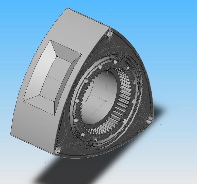
its perfectly to scale if any one was wondering.
here it comes.
i feel your pain of being a ME i'm a junior at UofA in ME right now. talk about a pain in the ***.
here is a pic of it for every one else :P.
its perfectly to scale if any one was wondering.
Last edited by ikari899; 06-08-07 at 12:35 AM.
Trending Topics
06-08-07, 12:51 AM
#9
engineer wanabe
Join Date: Jul 2005
Location: tucson
Posts: 409
Likes: 0
Received 0 Likes
on
0 Posts
hum i was wondering about how to get the perfect shape for the housing. i attempted using the Epitrochoid equations but i can not figure out what numbers to use for the exact same sized one as in the engine. i can get one that looks very similar but i want the exact one..
could you give me those numbers DeathandMajesty
for the R r and d values that apply to the 13b
x=(R+r)cos(theta)-d*cos((R+r)/r(theta))
y=(R+r)sin(theta)-d*sin((R+r)/r(theta))
could you give me those numbers DeathandMajesty
for the R r and d values that apply to the 13b
x=(R+r)cos(theta)-d*cos((R+r)/r(theta))
y=(R+r)sin(theta)-d*sin((R+r)/r(theta))
Last edited by ikari899; 06-08-07 at 12:57 AM.
06-08-07, 01:39 AM
#12
spoon!
hum i was wondering about how to get the perfect shape for the housing. i attempted using the Epitrochoid equations but i can not figure out what numbers to use for the exact same sized one as in the engine. i can get one that looks very similar but i want the exact one..
could you give me those numbers DeathandMajesty
for the R r and d values that apply to the 13b
x=(R+r)cos(theta)-d*cos((R+r)/r(theta))
y=(R+r)sin(theta)-d*sin((R+r)/r(theta))
could you give me those numbers DeathandMajesty
for the R r and d values that apply to the 13b
x=(R+r)cos(theta)-d*cos((R+r)/r(theta))
y=(R+r)sin(theta)-d*sin((R+r)/r(theta))
06-08-07, 03:35 PM
#14
Junior Member
Join Date: Apr 2005
Location: Sweden
Posts: 37
Likes: 0
Received 0 Likes
on
0 Posts
ikari899: I am very interested in your scale rotor. Id love to see 2D drawing so i can make my own rotor model perfect (i use SW 2003 so i must have a drawing like a picture). A small preview in my avatar and i calculate it to be 1/4 the weight as an mazda orginal.
There are other ways you can make the wankel shape but its time consuming.
There are other ways you can make the wankel shape but its time consuming.
06-08-07, 04:55 PM
#15
Junior Member
Join Date: Apr 2005
Location: Sweden
Posts: 37
Likes: 0
Received 0 Likes
on
0 Posts
You make a circle with the radius = e. Then you make dots 45 min or 270 deg. around the circle, that will be a total of 46 dots.
Draw a line from the first dot with the length = R. Draw a second line from the second dot with the same length. Then you make the angle of that line 2 deg. from the first line. Draw a third line from the third dot with the same length and make the angle 2 deg. from the second line. Repeat until you have atleast 1/4 epitrochoid.
I suggest you stop here because doing a full epitrochoid this way isnt fun at all and if you mess one up you might have to do it all over again, i dunno how many times i screwed up .
.
From here you can easily mirror it around to a full epitrochoid. Clean it up a bit and then you hit '3D curve' and select every dot in order all the way around. Dont forget to check 'Closed curve'.
Now you have a curve of the epitrochoid. Bad news is that you must have two epitrochoid curves in order to generate a 3D model since you cant extrude or cut with a 3D curve. You can simply copy the sketch and put it on an other parallel plane and then make an other 3D curve on that plane.
Now you should have two 3D curves featuring an epitrochoid. Now you can use Loft or Cut-Loft to generate a 3D epitrochoid.
This methods accuracy is good enough for 0.0000Xmm movements on the apexseals in a animated assembly. Yet not perfectly enough for solidworks which will give you error messages time to time and its a pain to get them away, often its just to move the assemble around a bit and its gone. A tip is to just have two corners of the rotor coincident to the epitrochoid.
A great program for wankel experimental models is the Rotary Engine Simulator by Michael Culley: http://mikesdriveway.com/EngineApp/
Draw a line from the first dot with the length = R. Draw a second line from the second dot with the same length. Then you make the angle of that line 2 deg. from the first line. Draw a third line from the third dot with the same length and make the angle 2 deg. from the second line. Repeat until you have atleast 1/4 epitrochoid.
I suggest you stop here because doing a full epitrochoid this way isnt fun at all and if you mess one up you might have to do it all over again, i dunno how many times i screwed up
.From here you can easily mirror it around to a full epitrochoid. Clean it up a bit and then you hit '3D curve' and select every dot in order all the way around. Dont forget to check 'Closed curve'.
Now you have a curve of the epitrochoid. Bad news is that you must have two epitrochoid curves in order to generate a 3D model since you cant extrude or cut with a 3D curve. You can simply copy the sketch and put it on an other parallel plane and then make an other 3D curve on that plane.
Now you should have two 3D curves featuring an epitrochoid. Now you can use Loft or Cut-Loft to generate a 3D epitrochoid.
This methods accuracy is good enough for 0.0000Xmm movements on the apexseals in a animated assembly. Yet not perfectly enough for solidworks which will give you error messages time to time and its a pain to get them away, often its just to move the assemble around a bit and its gone. A tip is to just have two corners of the rotor coincident to the epitrochoid.
A great program for wankel experimental models is the Rotary Engine Simulator by Michael Culley: http://mikesdriveway.com/EngineApp/
Last edited by Eson; 06-08-07 at 05:11 PM.
06-09-07, 06:00 PM
#16
Junior Member
Join Date: Jun 2007
Location: North Carolina
Posts: 6
Likes: 0
Received 0 Likes
on
0 Posts
O.o I guess I was kinda off.... lol Ikari and Eson, your drawings are amazing. I have been trying to learn it through trial and error. I thought my way worked...... I guess I need to learn some more Do you guys have any fresh ideas on internal combustion engines?
Do you guys have any fresh ideas on internal combustion engines?
06-10-07, 01:10 AM
#17
Full Member

Join Date: Oct 2005
Location: The Sticks Maine
Posts: 120
Likes: 0
Received 0 Likes
on
0 Posts
That last method is crazy. I just used excel to generate xyz coordinates of the epitrochiod then generated a curve in SW using the coordinates. It was accurate enough to get a working animation. I didn't bother getting correct scale though.
06-10-07, 02:49 AM
#18
(Terraplane)
I'll swap anyone with an engine model for a front end FC Pro-e Model or SW. It should be convertable to SW or visa vesa. By front end, I mean radiator, wheel wheels, radiator support and misc. It shows my A2W IC set-up which you can supress.
06-11-07, 10:07 AM
#19
engineer wanabe
Join Date: Jul 2005
Location: tucson
Posts: 409
Likes: 0
Received 0 Likes
on
0 Posts
tony you are going to have to show me how exactly to get SW to read the excel file and generate the curve. with that equation i can finally make a to scale one. weeeeeeeeeeeee
then its only a matter making a Eshaft and some stat gears and i will have a whole motor, to scale. which would be nice.
lol nope no fresh ideas :P.
P.S. Eson that is the most insane way i have seen to make a housing. good job! im going to be lazy and attempt it tonys way with excel.
then its only a matter making a Eshaft and some stat gears and i will have a whole motor, to scale. which would be nice.
lol nope no fresh ideas :P.
P.S. Eson that is the most insane way i have seen to make a housing. good job! im going to be lazy and attempt it tonys way with excel.
06-11-07, 10:27 AM
#20
engineer wanabe
Join Date: Jul 2005
Location: tucson
Posts: 409
Likes: 0
Received 0 Likes
on
0 Posts
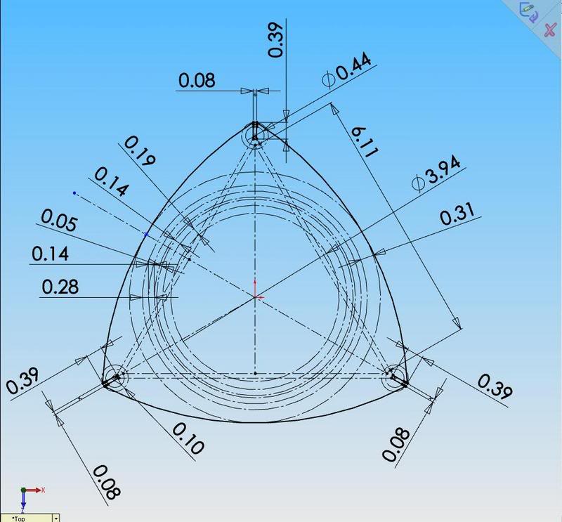
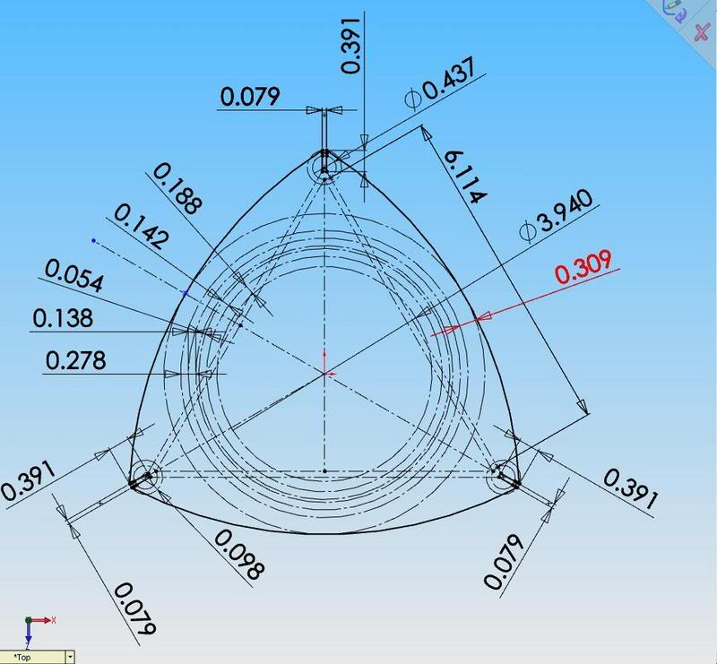
here is my 2d sketch of how i made the rotor. my own trick to making stuff is model it the exact way you measure it. so i laid down the dimensions only of the stuff i could measure with my calipers.
 06-11-07, 03:24 PM
#23
engineer wanabe
Join Date: Jul 2005
Location: tucson
Posts: 409
Likes: 0
Received 0 Likes
on
0 Posts
yeah inches. and those are exact numbers. so you can convert them to mm and i would bet they are within .0254mm of the actual number. i can not measure any smaller then .001" so to attempt to work within metric when i can only measure in standard at that accuracy wont work very well for me. just convert the numbers to metric they will be fine.
06-26-07, 02:06 PM
#24
spoon!
Just a bit of a bump; sat down with Excel and Solidworks and banged out a dimensionally accurate housing (well, every 5 degrees, but close enough for what I'm doing) Actually just placed points, mirrored them around, and used the spline tool. Dunno why Eson did it as a 3d sketch; as a 2d one with the spline tool you can extrude it and whatnot. Dunno if the spline tool was in 2003 though; I've got the 2005 version.
Fun part is that I made a simple 1-lobe e-shaft and rotor and it works. Even got the rotor flank radii right to not interfere with the housing, and tweaked the assembly mates to where I can enter e-shaft angle and come up with rotor position to find intake ports locations.
Fun part is that I made a simple 1-lobe e-shaft and rotor and it works. Even got the rotor flank radii right to not interfere with the housing, and tweaked the assembly mates to where I can enter e-shaft angle and come up with rotor position to find intake ports locations.
06-26-07, 02:26 PM
#25
Place your ad here...
I know you're looking for Solidworks specific files, but you are aware that SW can import pretty much all of the standard modeling formats (IGES, STEP, etc), right? This means that an individual with a completely different 3D modeling program can provide you with a part that you can use as a basis for your models.
As an aside, I found a picture of a rotor that I modeled a couple years ago using Autodesk Inventor PRO 10. I was playing with the "stitch face" command, and as evidenced by the improper bathtub shapes, I hadn't quite perfected it at the time I took this picture. I did make some subsequent improvements to the model, but I'd have to look through all of my files to find the right one.
For those who are curious, this was based on a parametric model. Meaning, you could input a few specific parameters, such as the displacement of the engine, and it would automatically recalculate all the proper dimensions.
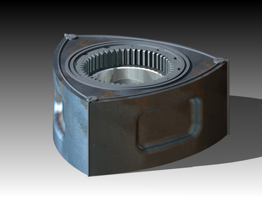
-Rob
As an aside, I found a picture of a rotor that I modeled a couple years ago using Autodesk Inventor PRO 10. I was playing with the "stitch face" command, and as evidenced by the improper bathtub shapes, I hadn't quite perfected it at the time I took this picture. I did make some subsequent improvements to the model, but I'd have to look through all of my files to find the right one.
For those who are curious, this was based on a parametric model. Meaning, you could input a few specific parameters, such as the displacement of the engine, and it would automatically recalculate all the proper dimensions.
-Rob

