Megasquirt Teensy 3.2 (Arduino-based) Megasquirt CAN display & Controller
 06-28-18, 09:46 AM
#1
Teensy 3.2 (Arduino-based) Megasquirt CAN display & Controller
So, I ended up diving into the world of arduino-like controllers partly because I wanted to play with something new, and partly because of project creep.
t started as a need to switch on a water-to-air intercooler pump at 35-40C in a way that I could adjust, since I didn't know what specific temperature would work best. I couldn't find any good thermo-switches in this range that I liked, so that got me looking at microcontrollers and temperature sensors (thermistors) to do the switching.
- Well... if I'm going to get a microcontroller, learn to program it & install a sensor in the intercooler, I may as well do one in the water-to-air heat exchanger to trigger the electric fan if that got too hot too.
- And, if I'm doing that, why not use it as a flexible way of triggering the low and high speed fans based on the coolant temperature too.
- It sure would be nice to be able to easily see and monitor these temperatures so I know when to set them to switch and make sure everything is working properly, so lets add a small display to this project.
- I don't want to have to bust out the laptop every time I want to change a temperature switching point, so we need an input method. Preferably something that allows for fairly easy number selection, and can switch between which of the temperatures are displayed on the screen.
- If I'm going to be changing temperatures on the fly, this controller will need to store those temperatures so that they dont get re-set the next time I start the car. The controller has to have some sort of EEPROM or something.
- Its kind-of a waste to just display a couple of temperatures on this screen, especially when I'm doing all of this to keep things like the MAT low and that sensor is already used by the Megasquirt. Hmm... the megasquirt can do CAN output, and there are a number of options for CAN with these microcontrollers...
- With all this work and capability, I want it to be easy to use and very visible when driving. The LCD clock in the warning light cluster has never worked, maybe I can put it there.
So, there we have a rough map of the course that project creep took. For reference, the mechanical side of the water-to-air intercooler and e-Fan project is here. There were a few other twists and turns along the way, but I'll spare you all the details as they haven't made the final cut for this project. I started with an Arduino Uno, which was too big for packaging near the warning cluster, so the I played with a couple other smaller controllers before settling on the Teensy 3.2, mostly because of the greater capability, the built-in CAN support, and the guidance and sample CAN code that was posted across a few places by I think the same person. Who-ever you are, thank you!
Since I think this may turn into a fairly long and detailed write-up, lets start with a carrot - this is what it currently looks and operates like, as installed in the car now.
Parts:
Teensy 3.2 microcontroller
Waveshare CAN transciever
Adafruit RGB backlit negative LCD display
Autometer 2253 thermistors
Various resistors, capacitors, diodes, transistors, LEDs, switches etc.
Prototyping boards etc.
Last edited by toplessFC3Sman; 06-28-18 at 09:56 AM.
 06-28-18, 10:56 AM
#2
Since this project completely revolves around the controller and display, lets start with the... thermistors. Well, the whole point (initially) was to read temperatures, so it makes sense in a way... at least to me...
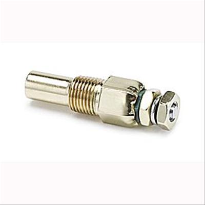
Anyhow, I eventually went with the Autometer 2253 replacement thermistor since it is quite compact (1/8" NPT threading), the calibration curve is public and posted online, and its sealed so it will work with water, oil, coolant - any of them. It would work in air too, but since it is sealed and the element is behind the brass body, it would likely have pretty poor response and could be dominated by the metal temperature that it is mounted in. The only negative is that it doesn't have an isolated ground - the sensor body is the ground which prevents you from isolating the sensor ground from the power ground. This could give some more noisy measurements or cause issues if the heat exchanger, IC core etc are not well grounded. There's no specific connector, just a screw terminal, which makes the connection easy but possibly less secure/less finished looking.
Anyhow, to avoid having to write an interpolation routine, and deal with the errors that it would give, I did a bit of curve-fitting. Since thermistors basically follow a power relationship with the absolute temperature, that was the basis of the fit (the equation is shown under the image below). This is the first part of the equation: 511 * resistance ^ -0.0812. To correct for some errors at low resistances, I added the second bit: + 120 / (resistance + 0.1). The +0.1 added to the resistance here is just to make sure the calculation doesn't do something screwy if the signal accidentally gets grounded and a 0 gets calculated for resistance. Finally, the -273.15 is converting from absolute temperature in Kelvin to the more familiar Celsius. Yea, thats right, Celsius. I'm an engineer, and I like my engineering units - screw these Fahrenheit, pound-force vs pound-weight stuff.

There is a bit more calculation involved in converting the raw A2D voltage into the resistance, and that is based on the specific wiring chosen for the sensor. Since these sensors don't have a separate sensor ground, one end of them will always be grounded. For the sake of space on the prototype board, and since we aren't dealing with extremely accurate sensors and will always have some level of noise on the signal, I decided to forego the fancy, precise wheatstone bridge for a more simple pull-up to the Teensy's 3.3V supply, which also simplifies the conversion code. The pull-up resistor was chosen to basically be around the value that we're switching at, so roughly 40 C, and a higher value will reduce the total current flow through the sensing signal which is important since the Teensy's internal voltage regulator is a bit limited in current capacity. Since we're measuring the voltage between the pull-up resistor and the temperature-dependent thermistor, calculation of the resistance from the A2D measured value is a simple ratio.
This is the whole wiring diagram for the Teensy 3.2 - we're really just looking at the part in the upper right corner with the four variable resistors (the thermistors), with 1.0 kOhm resistors to the 3.3V supply, and 0.01 microF capacitors to ground to do a little signal filtering.

Anyhow, I eventually went with the Autometer 2253 replacement thermistor since it is quite compact (1/8" NPT threading), the calibration curve is public and posted online, and its sealed so it will work with water, oil, coolant - any of them. It would work in air too, but since it is sealed and the element is behind the brass body, it would likely have pretty poor response and could be dominated by the metal temperature that it is mounted in. The only negative is that it doesn't have an isolated ground - the sensor body is the ground which prevents you from isolating the sensor ground from the power ground. This could give some more noisy measurements or cause issues if the heat exchanger, IC core etc are not well grounded. There's no specific connector, just a screw terminal, which makes the connection easy but possibly less secure/less finished looking.
Anyhow, to avoid having to write an interpolation routine, and deal with the errors that it would give, I did a bit of curve-fitting. Since thermistors basically follow a power relationship with the absolute temperature, that was the basis of the fit (the equation is shown under the image below). This is the first part of the equation: 511 * resistance ^ -0.0812. To correct for some errors at low resistances, I added the second bit: + 120 / (resistance + 0.1). The +0.1 added to the resistance here is just to make sure the calculation doesn't do something screwy if the signal accidentally gets grounded and a 0 gets calculated for resistance. Finally, the -273.15 is converting from absolute temperature in Kelvin to the more familiar Celsius. Yea, thats right, Celsius. I'm an engineer, and I like my engineering units - screw these Fahrenheit, pound-force vs pound-weight stuff.
There is a bit more calculation involved in converting the raw A2D voltage into the resistance, and that is based on the specific wiring chosen for the sensor. Since these sensors don't have a separate sensor ground, one end of them will always be grounded. For the sake of space on the prototype board, and since we aren't dealing with extremely accurate sensors and will always have some level of noise on the signal, I decided to forego the fancy, precise wheatstone bridge for a more simple pull-up to the Teensy's 3.3V supply, which also simplifies the conversion code. The pull-up resistor was chosen to basically be around the value that we're switching at, so roughly 40 C, and a higher value will reduce the total current flow through the sensing signal which is important since the Teensy's internal voltage regulator is a bit limited in current capacity. Since we're measuring the voltage between the pull-up resistor and the temperature-dependent thermistor, calculation of the resistance from the A2D measured value is a simple ratio.
This is the whole wiring diagram for the Teensy 3.2 - we're really just looking at the part in the upper right corner with the four variable resistors (the thermistors), with 1.0 kOhm resistors to the 3.3V supply, and 0.01 microF capacitors to ground to do a little signal filtering.
The following users liked this post:
Mugen1800 (01-22-21)
06-28-18, 04:29 PM
#3
The rest of the stuff on that wiring diagram are fairly straightforward. Adafruit has a bunch of good write-ups for connecting & controlling the screen, so that was really just about following the directions, setting the outputs correctly and it worked. The output circuits are pretty standard for driving a power NPN, although I ended up using a few TIP120s since the current for the relays was right at the edge of the specs for the 2N3904s I had and they wouldn't switch properly. The CAN transceiver requires 3.3V, ground, and the CAN TX & RX pins connected, so the wiring was simple enough that I omitted it from the image. One thing to note - the FlexCAN library that comes installed with the Arduino programmer is out-of-date, and the inputs changed so if you try to use that library with the code that I'm going to post IT WILL NOT WORK! You need a newer version of the FlexCAN library, and to change the file name of the old one so that the new library gets included in the compiled program.
The rotary encoder took a little bit of figuring out since it worked out a bit differently than I expected. It is a 3-channel setup (top 3 pins), where one channel will go open (pulled high) first, followed by the next, then the first will go low (connected to ground), followed by the next. That way, its possible to tell which way the encoder has rotated, not just that it has moved. Well, I was expecting each click or detent of the encoder would change the output by 1 phase in the image below, but it actually went through a whole cycle (so all 4 phases). This messed with my code at first since the rotary encoder library reported jumps of 4, but that was easy enough to correct for in the code. The encoder also had a built-in pushbutton, which connects the two bottom pins to one another when pressed.

Lastly, there was the headlight input. Since this goes to battery voltage (12 - 14V), I just put a couple of resistors in series to knock down the voltage in the middle of them to the 2 to 2.3V range, which is comfortably within the 1.7 to 3.3V range that will read as "High" for a digital input.
Of course, all this was first put together on a pair of prototype boards to make sure everything worked properly on the bench as the code was written and debugged. Some rheostats were used for the thermistors for testing and to make sure the outputs were working, etc.

Medusa mess!
First was the display - I had to do a bit of trimming and filing of the edges to make it short enough to fit in the warning light cluster. It was still as large as physically possible while still fitting where the clock had been, so everything else needed to fit within it's footprint behind it. I started with a general Radioshack IC prototyping board that I had laying around since it was laid out with two "lines" running the length of the board for regulated 5V and ground, as well as pads coming outward with 3 holes for each pin of the Teensy controller chip. It also had a row of 2-hole pads along the top and bottom which would be useful for the header to attach the screen. However, this board needed to be trimmed down a bit to fit within the cluster and behind the extents of the screen - this is it shortly after starting after soldering down the connections for the screen along the top (power, ground, various data lines, back-light LED colors, etc), then the voltage regulator on the right side, one of the TIP120 transistors on the left, the screw-connections from the CAN transceiver board on the lower left (the board itself is mounted underneath this proto board), and a bunch of resistors over capacitors for the inputs in the lower right. Ignore these - I made a mistake in the wiring with the resistors and they ended up getting relocated to over the CAN transceiver board where it was easier to add the external wires to go to the thermistors. The second transistor would be going directly to the right of the first transistor, but wasn't soldered down yet to give better access for soldering more components.

The third transistor is on the back-side of the proto board, as is the Teensy controller itself and the Waveshare CAN transceiver. The Teensy was on the back so that I could work on the opposite side of the board with good access directly to the copper pads. The Teensy would be installed with a set of headers so the controller can be removed without soldering, and to keep it out-of-the-way from most of the other soldering. Here it is just stuck in place for reference without the headers. The height of and access to the screw-terminals and size of the CAN transceiver dictated that it be on the back as well, and I just ran out of room on the front for the last of the transistors. The three wires here are the outputs to the relays for fan speed and IC water pump. This really highlights how much forethought really needed to go into placing all the components and trying to ensure access to get everything soldered down.

And the side view, without the headers for the Teensy controller or the screen in place. The screen would go on the bottom of this stack the way I'm holding it, and the Teensy would be lower than it is currently positioned with the headers. The micro-usb programming cable is currently attached and sticking off to the left - I want to keep this accessible for programming, but it won't be installed with this in place.

In these pictures its a bit further along - the headers are installed (I had to trim down the ones for the Teensy so it would sit comfortably between the screen and the prototype board), the screen is on and trimmed a bit, and the proto board is more complete. Filtered power from the cluster has been wired to it, but sensor input wiring and control **** wiring hasn't been attached. Also, you can see the power filtering circuitry to give a more steady 12V and switched 12V for the gauges and this project, now reconfigured and wedged into the spot for the left-most lights. The convertible doesn't have a hatch warning light, so these were empty already; I just had to hollow out the area to wedge these components into.


Since the rotary control **** & button combo that I am using to control the screen couldn't be mounted up next to it (no space, plus I don't want to be reaching all the way up there for it!), I needed to find a new place to put it. The ashtray seemed like a good candidate, especially since it gets too hot to stick a phone in anyway. Since I would be taking up that space, I decided to throw a few manual switches for the outputs in there, and some LEDs to show if it was on (whether by the manual switch, the controller output, or the thermoswitch for the fan speeds)

And now, with the proto-board mostly finished, and all the various wires added. I realize now that I didn't get a good picture of the board with the correct input resistor setup...oops.

For the remote control panel in the ash tray, all the connectors fit through the existing hole in the side, and it doesn't require any modification to the tray - it slides in tightly enough that it is snug. Everything seems to work as it should except when the key is in the accessory position. Then, the Fan High and IC Water Pump LEDs are lit, even though the devices themselves aren't on. I think I need to add some diodes so they don't ground through the relay coil, but I'm still figuring this bit out.. It also has the calibrate & status LED for the LC-1 wideband controller mounted on that panel.

The rotary encoder took a little bit of figuring out since it worked out a bit differently than I expected. It is a 3-channel setup (top 3 pins), where one channel will go open (pulled high) first, followed by the next, then the first will go low (connected to ground), followed by the next. That way, its possible to tell which way the encoder has rotated, not just that it has moved. Well, I was expecting each click or detent of the encoder would change the output by 1 phase in the image below, but it actually went through a whole cycle (so all 4 phases). This messed with my code at first since the rotary encoder library reported jumps of 4, but that was easy enough to correct for in the code. The encoder also had a built-in pushbutton, which connects the two bottom pins to one another when pressed.
Lastly, there was the headlight input. Since this goes to battery voltage (12 - 14V), I just put a couple of resistors in series to knock down the voltage in the middle of them to the 2 to 2.3V range, which is comfortably within the 1.7 to 3.3V range that will read as "High" for a digital input.
Of course, all this was first put together on a pair of prototype boards to make sure everything worked properly on the bench as the code was written and debugged. Some rheostats were used for the thermistors for testing and to make sure the outputs were working, etc.
Medusa mess!
First was the display - I had to do a bit of trimming and filing of the edges to make it short enough to fit in the warning light cluster. It was still as large as physically possible while still fitting where the clock had been, so everything else needed to fit within it's footprint behind it. I started with a general Radioshack IC prototyping board that I had laying around since it was laid out with two "lines" running the length of the board for regulated 5V and ground, as well as pads coming outward with 3 holes for each pin of the Teensy controller chip. It also had a row of 2-hole pads along the top and bottom which would be useful for the header to attach the screen. However, this board needed to be trimmed down a bit to fit within the cluster and behind the extents of the screen - this is it shortly after starting after soldering down the connections for the screen along the top (power, ground, various data lines, back-light LED colors, etc), then the voltage regulator on the right side, one of the TIP120 transistors on the left, the screw-connections from the CAN transceiver board on the lower left (the board itself is mounted underneath this proto board), and a bunch of resistors over capacitors for the inputs in the lower right. Ignore these - I made a mistake in the wiring with the resistors and they ended up getting relocated to over the CAN transceiver board where it was easier to add the external wires to go to the thermistors. The second transistor would be going directly to the right of the first transistor, but wasn't soldered down yet to give better access for soldering more components.
The third transistor is on the back-side of the proto board, as is the Teensy controller itself and the Waveshare CAN transceiver. The Teensy was on the back so that I could work on the opposite side of the board with good access directly to the copper pads. The Teensy would be installed with a set of headers so the controller can be removed without soldering, and to keep it out-of-the-way from most of the other soldering. Here it is just stuck in place for reference without the headers. The height of and access to the screw-terminals and size of the CAN transceiver dictated that it be on the back as well, and I just ran out of room on the front for the last of the transistors. The three wires here are the outputs to the relays for fan speed and IC water pump. This really highlights how much forethought really needed to go into placing all the components and trying to ensure access to get everything soldered down.
And the side view, without the headers for the Teensy controller or the screen in place. The screen would go on the bottom of this stack the way I'm holding it, and the Teensy would be lower than it is currently positioned with the headers. The micro-usb programming cable is currently attached and sticking off to the left - I want to keep this accessible for programming, but it won't be installed with this in place.
In these pictures its a bit further along - the headers are installed (I had to trim down the ones for the Teensy so it would sit comfortably between the screen and the prototype board), the screen is on and trimmed a bit, and the proto board is more complete. Filtered power from the cluster has been wired to it, but sensor input wiring and control **** wiring hasn't been attached. Also, you can see the power filtering circuitry to give a more steady 12V and switched 12V for the gauges and this project, now reconfigured and wedged into the spot for the left-most lights. The convertible doesn't have a hatch warning light, so these were empty already; I just had to hollow out the area to wedge these components into.
Since the rotary control **** & button combo that I am using to control the screen couldn't be mounted up next to it (no space, plus I don't want to be reaching all the way up there for it!), I needed to find a new place to put it. The ashtray seemed like a good candidate, especially since it gets too hot to stick a phone in anyway. Since I would be taking up that space, I decided to throw a few manual switches for the outputs in there, and some LEDs to show if it was on (whether by the manual switch, the controller output, or the thermoswitch for the fan speeds)
And now, with the proto-board mostly finished, and all the various wires added. I realize now that I didn't get a good picture of the board with the correct input resistor setup...oops.
For the remote control panel in the ash tray, all the connectors fit through the existing hole in the side, and it doesn't require any modification to the tray - it slides in tightly enough that it is snug. Everything seems to work as it should except when the key is in the accessory position. Then, the Fan High and IC Water Pump LEDs are lit, even though the devices themselves aren't on. I think I need to add some diodes so they don't ground through the relay coil, but I'm still figuring this bit out.. It also has the calibrate & status LED for the LC-1 wideband controller mounted on that panel.
Last edited by toplessFC3Sman; 06-29-18 at 09:02 AM.
06-29-18, 08:46 AM
#5
Last but certainly not least, the code. Let me preface this with the statement that I am definitely not a programmer by trade and am mostly self-taught, so this may be a bit messy. I know that I am using a ton of global variables which seems to be frowned on, and I probably pass some of them unnecessarily between functions and commit other no-nos. I tried to comment the code as I was writing it to delineate sections and intent, and ultimately the whole thing does work as intended so I am not too inclined to go back in and change things. Also, all of my de-bugging messages sent across Serial to the laptop are still active - I know that these could be turned off to make it run more quickly, but there is really no need. I had to put in a timer to slow down the update rate of the display, otherwise it was changing too quickly making it difficult to read the numbers if they were changing quickly or if there was some noise in the signal.
Lastly, this all uses the 11-bit CAN messages that MS3-extra and MS2-extra v3.4.0 and up support, so this won't work with earlier builds of MS2-extra.
One other note is on the libraries that I included - this tripped me up when trying to get CAN working so I'm posting it here to hopefully save someone else the headache.
- LiquidCrystal.h - This was the default one that came with installing the Arduino programmer 1.8.5
- Rotary.h - This one I got from a google search off github - I think it was this one
- EEPROM.h - This came with the Arduino programmer
- string.h - I think I had included this because I was attempting to create longer strings to display both in the serial monitor and on the LCD, but I don't think I actually use anything from it at this point.
- FlexCAN.h - This one NEEDS to be downloaded and installed - the default version of this library has a different input order and doesn't throw an error, but CAN simply doesn't work since it takes the first number input as a CAN filter, not as the data rate. I got a new version here.
- kinetis_flexcan.h - This came with FlexCAN.h, but I am not sure if its necessary for this code. I included it because the project that I was looking at as a basis for reading the CAN messages had it
#include <LiquidCrystal.h>
#include <Rotary.h>
#include <EEPROM.h>
#include <string.h>
#include <FlexCAN.h>
#include <kinetis_flexcan.h>
/* Keeping Track of Pins for Teensy 3.2:
A0 (D14) = IC Heat Exchanger T
A1 (D15) = IC Out T
A2 (D16) = Rad Out T
A3 (D17) = Eng Out T
A4 (D18) = Encoder Pin A
A5 (D19) = Encoder Pin B
A6 (D20) = Encoder Button
A7 (D21) = LCD Red Ground (PWM)
A8 (D22) = LCD Green Ground (PWM)
A9 (D23) = LCD Blue Ground (PWM)
A10 =
A11 =
A12 =
A13 =
A14 (DAC) =
A15 (D26) =
A16 (D27) =
A17 (D28) =
A18 (D29) =
A19 (D30) =
A20 (D31) =
D0 =
D1 =
D2 = Headlight Switch (In)
D3 = CAN TX
D4 = CAN RX
D5 = Rad Fan Low Spd
D6 = Rad Fan High Spd
D7 = LCD RS pin
D8 = LCD E pin
D9 = LCD D4 pin
D10 = LCD D5 pin
D11 = LCD D6 pin
D12 = LCD D7 pin
D13 = IC Water Pump
D24 =
D25 =
D32 =
D33 =
*/
const float Rp = 1000.0; // Resistance of pull-up for T meas
// Power Fit constants for Autometer 2253
const float c = 511.0; // Multiplicative fitting constant
const float b = -0.0812; // Exponential fitting constant
const float d = 120.0; // Division fitting constant
// ------------- Input Setup
const int numIns = 32; // Number of inputs
const int inPin = {14, 15, 16, 17}; //{0, 1, 2, 3};
const int lastT = 3; // Last Temperature reading (0, 1, 2)
const int canGroup = { -1, -1, -1, -1, 0, // 1
2, 2, 2, 3, // 2
0, 0, -1, -1, // 3
4, 5, 5, 6, // 4
3, 3, 4, 4, // 5
1, 7, 57, 57, // 6
3, 17, 17, 28, // 7
43, 43, 43, // 8
};
const int canOffset = { -1, -1, -1, -1, 6, // 1
2, 4, 6, 0, // 2
2, 4, -1, -1, // 3
6, 0, 2, 0, // 4
4, 6, 2, 4, // 5
0, 0, 2, 4, // 6
2, 0, 4, 0, // 7
0, 1, 7, // 8
};
const int canSize = { -1, -1, -1, -1, 2, // 1
2, 2, 2, 2, // 2
2, 2, -2, -3, // 3
2, 2, 2, 2, // 4
2, 2, 2, 2, // 5
2, 2, 2, 2, // 6
2, 2, 1, 2, // 7
1, 1, 1, // 8
};
const int canMlt = { 0, 0, 0, 0, 1, // 1
1, 5, 5, 1, // 2
1, 1, 1, 1, // 3
1, 1, 1, 1, // 4
1, 1, 1, 1, // 5
1, 1, 1, 1, // 6
1, 1, 1, 1, // 7
1, 1, 1, // 8
};
const int canDiv = { 0, 0, 0, 0, 1, // 1
10, 90, 90, 10, // 2
1000, 1000, 1, 1, // 3
10, 10, 10, 10, // 4
10, 10, 10, 10, // 5
10, 10, 10, 10, // 6
10, 10, 1, 1, // 7
1, 1, 1, // 8
};
const int canAdd = { 0, 0, 0, 0, 0, // 1
0, -18, -18, 0, // 2
0, 0, 0, 0, // 3
0, 0, 0, 0, // 4
0, 0, 0, 0, // 5
0, 0, 0, 0, // 6
0, 0, 0, 0, // 7
0, 0, 0, // 8
};
// DutyCyc1 & DutyCyc2 must appear after engine speed & PW1 & PW2
char label[numIns][12] = {"IC Hx T", "IC Out T", "Rad Out T", "Eng Out T", "EngSpd", //1
"MAP", "MAT", "Cool T", "Throt Pos", // 2
"PulseWd1", "PulseWd2", "DutyCyc1", "DutyCyc2", // 3
"AirDensCor", "WarmUpCor", "AccelCor", "TotalCor", // 4
"AFR1", "AFR2", "EGO Cor 1", "EGO Cor 2", // 5
"Spark", "WarmUpAdv", "IdleAdv", "MATRet", // 6
"Batt V", "BoostTarg", "BoostDuty", "IdleTarg", // 7
"SyncCount", "SyncReason", "SparkErr", // 8
};
char units[numIns][4] = {"^C", "^C", "^C", "^C", "RPM", // 1
"kPa", "^C", "^C", "%", // 2
"ms", "ms", "%", "%", // 3
"%", "%", "%", "%", // 4
"", "", "%", "%", // 5
"^bT", "^", "^", "^bT", // 6
"V", "kPa", "%", "RPM", // 7
"", "", "%", // 8
};
float conVal = {0.0, 0.0, 0.0, 0.0, 0.0, // 1
0.0, 0.0, 0.0, 0.0, // 2
0.0, 0.0, 0.0, 0.0, // 3
0.0, 0.0, 0.0, 0.0, // 4
0.0, 0.0, 0.0, 0.0, // 5
0.0, 0.0, 0.0, 0.0, // 6
0.0, 0.0, 0.0, 0.0, // 7
0.0, 0.0, 0.0, 0.0, // 8
};
// ------------- CAN setup
const int canBaseID = 1520;
FlexCAN CANbus(500000); // 500kHz frequency
static CAN_message_t rxmsg;
// ------------- Encoder Setup
// this is for a rotary encoder using 2-channel gray logic
#define encoderPinA 18 //A5
#define encoderPinB 19 //A4
const int encoderButton = 20; //A6;
// Rotary encoder is wired with the common to ground and the two
// outputs to pins 2 and 3 (hardware interrupts)
Rotary rotary = Rotary(encoderPinA, encoderPinB);
int curPos = 0;
int prevPos = 0;
int changePos = 0;
unsigned long pressTime;
// ------------- Output Setup
const int numOuts = 3;
// 5 - Fan Low
// 6 - Fan High
// 13 - Pump On
char outName[numOuts][10] = {"Fan Low", "Fan High", "IC Pump"};
const int outPin = {5, 6, 13};
// ------------- Conditional Setup
// Any "true" trigger in the column for the output pin
// will turn on that output. Each row corresponds to
// a condition (last one is manual override)
const int numConds = 4;
bool trig[numConds + 1][numOuts] = { {false, false, false},
{false, false, false},
{false, false, false},
{false, false, false},
{false, false, false}};
// 0 - IC Out T > 35 = Pump On
// 1 - IC Hx T > 35 = Fan On Low
// 2 - Tstat T > 90 = Fan On Low
// 3 - Tstat T > 100 = Fan On High
int setPt[4] = {35, 35, 90, 100}; // Move Me to EEPROM
int hyst[4] = { 5, 5, 5, 5};
const int sigN[4] = { 1, 0, 3, 3};
const int outN[4] = { 2, 0, 0, 1};
char strBuf[8];
const int eepLocSetPt[4] = { 12, 16, 20, 24};
// ------------- Display
//lcd(RS, E, D4, D5, D6, D7)
LiquidCrystal lcd(7, 8, 9, 10, 11, 12);
const int numRows = 2;
const int numCols = 16;
const int backLPin[3] = {A7, A8, A9}; // A7 A8 A9
// Color values: 0 = Red, 15 = Green, 30 = Blue, 45 == 0 = Red
// Brightness values: 0 = dim, 24 = full color 47 = full bright (white)
int headLightPin = 2;
bool headLightOn = false;
int color[2] = {2, 2};
int bright[2] = {24, 10};
const int eepLocCol[2] = {28, 32}; // EEPROM memory address
const int eepLocBri[2] = {36, 40}; // EEPROM memory address
char daynight[2][6] = {"Day", "Night"};
int topRow = 0; // Version of eepLocTop in memory
int botRow = 1; // Version of eepLocBot in memory
const int eepLocTop = 4; // EEPROM memory address
const int eepLocBot = 8; // EEPROM memory address
// ------------- Other
int rawVint;
float rawVfloat;
int randVar;
int randVar2;
int randVar3;
int i;
int j;
int sig;
int out;
int inc;
const int eepKey = 28; // EEPROM key - used to see if vars from the current code are in memory
bool turnOn = false;
bool mode = false; // false is normal display, true is change setpoints
bool sel = false; // selection made by holding down button for > 1 sec
int selLine = 0; // selection line to display
int modeLine = -1; // which programming menu item is selected if mode == true
const int numOps = 14;
int refreshInt = 300; // Refresh displayed numbers every X ms
unsigned long dispTime = millis();
int refreshCAN = 1000; // If CAN is not read every X ms, set all CAN to -999
unsigned long canTime = millis();
bool firstTime = false;
void setup() {
// put your setup code here, to run once:
Serial.begin(9600);
Serial.println("Hello Dave");
CANbus.begin();
pinMode(encoderPinA, INPUT_PULLUP);
pinMode(encoderPinB, INPUT_PULLUP);
attachInterrupt(encoderPinA, rotate, CHANGE);
attachInterrupt(encoderPinB, rotate, CHANGE);
lcd.begin(numRows, numCols);
lcd.clear();
for (i = 0; i < numOuts; i++) {
pinMode(outPin[i], OUTPUT);
digitalWrite(outPin[i], HIGH);
}
pinMode(headLightPin, INPUT);
for (i = 0; i < 3; i++) {
pinMode(backLPin[i], OUTPUT);
}
pinMode(encoderButton, INPUT_PULLUP);
// Initialize Counter Position to current
prevPos = curPos;
changePos = 0;
// Create custom characters
byte degreeSign[8] = {
B01110,
B01010,
B01110,
B00000,
B00000,
B00000,
B00000,
};
lcd.createChar(0, degreeSign);
byte lowSel[8] = {
B10000,
B11000,
B10100,
B10000,
B10000,
B10000,
B00000,
};
lcd.createChar(1, lowSel);
byte midSel[8] = {
B00100,
B01110,
B10101,
B00100,
B00100,
B00100,
B00000,
};
lcd.createChar(2, midSel);
byte highSel[8] = {
B00001,
B00011,
B00101,
B00001,
B00001,
B00001,
B00000,
};
lcd.createChar(3, highSel);
byte leftSel[8] = {
B00000,
B00000,
B00001,
B00000,
B00000,
B00000,
B00000,
};
lcd.createChar(4, leftSel);
byte rightSel[8] = {
B00000,
B00000,
B10000,
B00000,
B00000,
B00000,
B00000,
};
lcd.createChar(5, rightSel);
// Set Up or Pull Values from EEPROM
if (EEPROMReadInt(0) != eepKey) {
// If the key is not correct, then EEPROM is not written
Serial.println("EEPROM Key was NOT correct, writing setpoints to EEPROM!!!!!");
EEPROMWriteInt(0,eepKey);
EEPROMWriteInt(eepLocTop,topRow);
EEPROMWriteInt(eepLocBot,botRow);
//EEPROM.put(0,eepKey);
//EEPROM.put(eepLocTop,topRow);
//EEPROM.put(eepLocBot,botRow);
for (i = 0; i < numConds; i++) {
EEPROMWriteInt(eepLocSetPt[i],setPt[i]);
//EEPROM.put(eepLocSetPt[i],setPt[i]);
}
EEPROMWriteInt(eepLocCol[0],color[0]);
EEPROMWriteInt(eepLocCol[1],color[1]);
EEPROMWriteInt(eepLocBri[0],bright[0]);
EEPROMWriteInt(eepLocBri[1],bright[1]);
//EEPROM.put(eepLocCol[0],color[0]);
//EEPROM.put(eepLocCol[1],color[1]);
//EEPROM.put(eepLocBri[0],bright[0]);
//EEPROM.put(eepLocBri[1],bright[1]);
}
else {
Serial.println("EEPROM Key was correct");
topRow = EEPROMReadInt(eepLocTop);
botRow = EEPROMReadInt(eepLocBot);
//EEPROM.get(eepLocTop,topRow);
//EEPROM.get(eepLocBot,botRow);
for (i = 0; i < numConds; i++) {
setPt[i] = EEPROMReadInt(eepLocSetPt[i]);
//EEPROM.get(eepLocSetPt[i],setPt[i]);
}
color[0] = EEPROMReadInt(eepLocCol[0]);
color[1] = EEPROMReadInt(eepLocCol[1]);
bright[0] = EEPROMReadInt(eepLocBri[0]);
bright[1] = EEPROMReadInt(eepLocBri[1]);
//EEPROM.get(eepLocCol[0],color[0]);
//EEPROM.get(eepLocCol[1],color[1]);
//EEPROM.get(eepLocBri[0],bright[0]);
//EEPROM.get(eepLocBri[1],bright[1]);
}
headLightOn = digitalRead(headLightPin);
colorPWM(headLightOn);
writeNamestoLCD(topRow, 0, label);
writeNamestoLCD(botRow, 1, label);
}
void loop() {
// Check status of encoder button, how long it has been pressed
if (!digitalRead(encoderButton) && (millis() - pressTime) > 1000) {
// if button is still pressed after 1 second, switch mode (Normal to
// Set-Point and back)
mode = !mode;
lcd.clear();
lcd.setCursor(0,0);
lcd.write("Options / Setup");
while (!digitalRead(encoderButton)) { } // Wait until button released
delay(500);
pressTime = millis();
Serial.print("Switching Mode to "); Serial.println(mode);
sel = false;
firstTime = true;
modeLine = -1;
selLine = 0;
lcd.clear();
// Write initial lines to LCD if mode changes
if (!mode) {
writeNamestoLCD(topRow, 0, label);
writeNamestoLCD(botRow, 1, label);
}
}
else if (!digitalRead(encoderButton) && (millis() - pressTime) > 500) {
// if button is still pressed after 0.5 seconds, selection has been made
// within current mode
sel = true;
Serial.println("Selection Made!");
Serial.print("Time Diff = ");
Serial.println(millis() - pressTime);
}
else if (digitalRead(encoderButton)) {
// If no button is pressed, keep setting the "pressTime" counter to the
// current time so that a difference will not accumulate.
pressTime = millis();
}
else {
Serial.print("Time Diff = ");
Serial.println(millis() - pressTime);
}
if (mode) {
// Change Display Lines, Set-Points for each Condition, Force Outs On, Change Colors etc
switch (modeLine) {
case -1:
// No selection made in base menu, still displaying base menu items
if (curPos != prevPos) {
changePos = curPos - prevPos;
Serial.print("selLine = "); Serial.print(selLine); Serial.print(", Change of ");
Serial.print(changePos); Serial.print(" = ");
selLine = mod_AlwaysPos(selLine + changePos, numOps);
Serial.println(selLine);
prevPos = curPos;
firstTime = true;
}
// Do different things based on second option
if (selLine <= 0) {
// Change Disp 1
if (firstTime) {
lcd.clear();
lcd.setCursor(0,0);
lcd.write("Change Display 1");
writeNamestoLCD(topRow, 1, label);
firstTime = false;
}
if (millis() - dispTime >= refreshInt) {
writeNumstoLCD(topRow, 1, conVal, units);
dispTime = millis();
}
}
else if (selLine <= 1) {
// Change Disp 2
if (firstTime) {
lcd.clear();
lcd.setCursor(0,0);
lcd.write("Change Display 2");
writeNamestoLCD(botRow, 1, label);
firstTime = false;
}
if (millis() - dispTime >= refreshInt) {
writeNumstoLCD(botRow, 1, conVal, units);
dispTime = millis();
}
}
else if (selLine <= 5) {
// Change Set Point
if (firstTime) {
randVar = selLine - 2;
lcd.clear();
lcd.setCursor(0,0);
lcd.write(outName[outN[randVar]]);
lcd.write(" On if");
lcd.setCursor(0,1);
lcd.write(label[sigN[randVar]]);
lcd.write(" > ");
writeNumsBasic(1, setPt[randVar], units[sigN[randVar]], 3, 0);
firstTime = false;
}
}
else if (selLine <= 8 ) {
// Force Output On
if (firstTime) {
randVar = selLine - 6;
lcd.clear();
lcd.setCursor(0,0);
lcd.write("Turn ");
lcd.write(outName[randVar]);
lcd.write(" On");
lcd.setCursor(0,1);
if (trig[numConds][randVar]) { lcd.write("Yes"); }
else { lcd.write("No"); }
firstTime = false;
}
}
else if (selLine <= 10) {
// Change Display Color
if (firstTime) {
randVar = selLine - 9;
lcd.clear();
lcd.setCursor(0,0);
lcd.write("Change Display");
lcd.setCursor(0,1);
lcd.write("Color for ");
lcd.write(daynight[randVar]);
firstTime = false;
}
}
else if (selLine <= 12) {
// Change Display Brightness
if (firstTime) {
randVar = selLine - 11;
lcd.clear();
lcd.setCursor(0,0);
lcd.write("Change Display");
lcd.setCursor(0,1);
lcd.write("Light for ");
lcd.write(daynight[randVar]);
firstTime = false;
}
}
else if (selLine <= 13) {
// Exit to Display Mode
if (firstTime) {
lcd.clear();
lcd.setCursor(0,0);
lcd.write("Exit to Display");
firstTime = false;
}
}
else {
// Don't know what happened here
Serial.print("selLine = "); Serial.print(selLine);
Serial.println(", Not in defined option");
mode = false;
}
// If a selection is made, save the selected line (option) as the mode line
if (sel) {
Serial.print("Selection Made = "); Serial.println(selLine);
pressTime = millis();
modeLine = selLine;
selLine = 0;
sel = false;
firstTime = true;
lcd.clear();
}
break;
case 0:
// Selection 0, Change Display Line 1
if (curPos != prevPos || firstTime) {
// Run this if it is the first time displaying current
// options, or if encoder changed position
firstTime = false;
changePos = curPos - prevPos;
Serial.print("topRow = "); Serial.print(topRow); Serial.print(", Change of ");
Serial.print(changePos); Serial.print(" = ");
topRow = mod_AlwaysPos(topRow + changePos, numIns);
Serial.println(topRow);
selLine = mod_AlwaysPos(topRow + 1, numIns);
prevPos = curPos;
writeNamestoLCD(topRow, 0, label);
writeNamestoLCD(selLine, 1, label);
}
if (millis() - dispTime >= refreshInt) {
writeNumstoLCD(topRow, 0, conVal, units);
writeNumstoLCD(selLine, 1, conVal, units);
dispTime = millis();
lcd.setCursor(numCols - 1, 0);
lcd.write("<<");
}
if (sel) {
// Store new topRow in EEPROM, Return to display operation -------------------------
Serial.print("Selection Made = "); Serial.print(topRow);
Serial.print(", Storing in EEPROM address "); Serial.println(eepLocTop);
EEPROMWriteInt(eepLocTop,topRow);
//EEPROM.put(eepLocTop,topRow);
mode = false;
firstTime = true;
}
break;
case 1:
// Selection 1, Change Display Line 2
if (curPos != prevPos || firstTime) {
// Run this if it is the first time displaying current
// options, or if encoder changed position
firstTime = false;
changePos = curPos - prevPos;
Serial.print("botRow = "); Serial.print(botRow); Serial.print(", Change of ");
Serial.print(changePos); Serial.print(" = ");
botRow = mod_AlwaysPos(botRow + changePos, numIns);
Serial.println(botRow);
selLine = mod_AlwaysPos(botRow + 1, numIns);
prevPos = curPos;
writeNamestoLCD(botRow, 0, label);
writeNamestoLCD(selLine, 1, label);
}
if (millis() - dispTime >= refreshInt) {
writeNumstoLCD(botRow, 0, conVal, units);
writeNumstoLCD(selLine, 1, conVal, units);
dispTime = millis();
lcd.setCursor(numCols - 1, 0);
lcd.write("<<");
}
if (sel) {
// Store new botRow in EEPROM, Return to display operation -------------------------
Serial.print("Selection Made = "); Serial.print(botRow);
Serial.print(", Storing in EEPROM address "); Serial.println(eepLocBot);
EEPROMWriteInt(eepLocBot,botRow);
//EEPROM.put(eepLocBot,botRow);
mode = false;
firstTime = true;
}
break;
case 2:
case 3:
case 4:
case 5:
// Change the setpoint at which an output turns on
if (curPos != prevPos || firstTime) {
//randVar = mod_AlwaysPos(modeLine - 2,numConds);
randVar = modeLine - 2;
firstTime = false;
changePos = curPos - prevPos;
Serial.print("SetPt = "); Serial.print(setPt[randVar]); Serial.print(", Change of ");
Serial.print(changePos); Serial.print(" = ");
setPt[randVar] = setPt[randVar] + changePos;
Serial.println(setPt[randVar]);
lcd.clear();
lcd.setCursor(0,0);
lcd.write(outName[outN[randVar]]);
lcd.write(" On if");
lcd.setCursor(0,1);
for (i = 0; i < numCols - 4 - strlen(units[sigN[randVar]]); i++) {
lcd.write(">");
}
for (i = numCols - 4 - strlen(units[sigN[randVar]]); i < numCols; i++) {
lcd.write(" ");
}
writeNumsBasic(1, setPt[randVar], units[sigN[randVar]], 3, 0);
prevPos = curPos;
}
if (sel) {
// Store new setPt in EEPROM, Return to display operation -------------------------
Serial.print("Set Point Changed = "); Serial.print(setPt[randVar]);
Serial.print(", Storing in EEPROM Address "); Serial.println(eepLocSetPt[randVar]);
EEPROMWriteInt(eepLocSetPt[randVar],setPt[randVar]);
//EEPROM.put(eepLocSetPt[randVar],setPt[randVar]);
mode = false;
firstTime = true;
}
break;
case 6:
case 7:
case 8:
// Force an output on
if (curPos != prevPos || firstTime) {
// randVar = mod_AlwaysPos(modeLine - 6,numOuts);
randVar = modeLine - 6;
if (!firstTime) {
trig[numConds][randVar] = !trig[numConds][randVar];
}
firstTime = false;
lcd.clear();
lcd.setCursor(0,0);
lcd.write("Turn ");
lcd.write(outName[randVar]);
lcd.write(" On");
lcd.setCursor(0,1);
if (trig[numConds][randVar]) { lcd.write(">> Yes"); }
else { lcd.write(">> No"); }
prevPos = curPos;
}
if (sel) {
mode = false;
firstTime = true;
Serial.print("Selection Made, "); Serial.print(outName[randVar]);
Serial.print(" = ");Serial.println(trig[numConds][randVar]);
}
break;
case 9:
case 10:
// Change Display Color
randVar = modeLine - 9;
if (firstTime) {
lcd.clear();
lcd.setCursor(0,0);
lcd.write("R----G----B----R");
}
if (curPos != prevPos || firstTime) {
changePos = curPos - prevPos;
// limit color to the range 0 to 44
color[randVar] = mod_AlwaysPos(color[randVar] + changePos,45);
Serial.print("Color = ["); Serial.print(color[0]); Serial.print(", ");
Serial.print(color[1]); Serial.println("]");
Serial.print("Bright = ["); Serial.print(bright[0]); Serial.print(", ");
Serial.print(bright[1]); Serial.println("]");
colorPWM(randVar); // color & bright are global vars
lcd.setCursor(0,1);
randVar2 = (color[randVar]+1)/3; // Display Cell to put marker in
randVar3 = mod_AlwaysPos(color[randVar]+1,3) + 1; // Custom Character to put in
for (int ii = 0; ii < numCols; ii++) {
if (ii == randVar2) {
// Write Arrow Marker in correct location
lcd.write(byte(randVar3));
}
else if (ii == randVar2 - 1 && randVar3 == 1) {
lcd.write(byte(4));
}
else if (ii == randVar2 + 1 && randVar3 == 3) {
lcd.write(byte(5));
}
else {
lcd.write(" ");
}
}
prevPos = curPos;
}
firstTime = false;
if (sel) {
// Store new color in EEPROM, Return to display operation -------------------------
mode = false;
firstTime = true;
Serial.print("Selection Made, "); Serial.print(daynight[randVar]);
Serial.print(" = "); Serial.println(color[randVar]);
EEPROMWriteInt(eepLocCol[randVar],color[randVar]);
//EEPROM.put(eepLocCol[randVar],color[randVar]);
headLightOn = digitalRead(headLightPin);
colorPWM(headLightOn); // color & bright are global vars
}
break;
case 11:
case 12:
// Change Display Brightness
randVar = modeLine - 11;
if (firstTime) {
lcd.clear();
lcd.setCursor(0,0);
lcd.write("Dim-------Bright");
}
if (curPos != prevPos || firstTime) {
changePos = curPos - prevPos;
// limit brightness to the range 0 to 47
bright[randVar] = max(min(bright[randVar] + changePos,47),0);
Serial.print("Color = ["); Serial.print(color[0]); Serial.print(", ");
Serial.print(color[1]); Serial.println("]");
Serial.print("Bright = ["); Serial.print(bright[0]); Serial.print(", ");
Serial.print(bright[1]); Serial.println("]");
colorPWM(randVar); // color & bright are global vars
lcd.setCursor(0,1);
randVar2 = (bright[randVar]+1)/3; // Display Cell to put marker in
randVar3 = mod_AlwaysPos(bright[randVar]+1,3) + 1; // Custom Character to put in
for (int ii = 0; ii < numCols; ii++) {
if (ii == randVar2) {
// Write Arrow Marker in correct location
lcd.write(byte(randVar3));
}
else if (ii == randVar2 - 1 && randVar3 == 1) {
lcd.write(byte(4));
}
else if (ii == randVar2 + 1 && randVar3 == 3) {
lcd.write(byte(5));
}
else {
lcd.write(" ");
}
}
prevPos = curPos;
}
firstTime = false;
if (sel) {
// Store new brightness in EEPROM, Return to display operation -------------------------
mode = false;
firstTime = true;
Serial.print("Selection Made, "); Serial.print(daynight[randVar]);
Serial.print(" = "); Serial.println(bright[randVar]);
EEPROMWriteInt(eepLocBri[randVar],bright[randVar]);
//EEPROM.put(eepLocBri[randVar],bright[randVar]);
headLightOn = digitalRead(headLightPin);
colorPWM(headLightOn); // color & bright are global vars
}
break;
case 13:
// Exit to Display Mode
Serial.println("Exiting to Display Mode");
mode = false;
break;
}
}
else {
// Normal operation, displaying Inputs & switching with Conditions
sel = false;
if (curPos != prevPos || firstTime) {
firstTime = false;
changePos = curPos - prevPos;
Serial.print("topRow = "); Serial.print(topRow); Serial.print(", Change of ");
Serial.print(changePos); Serial.print(" = ");
topRow = mod_AlwaysPos(topRow + changePos, numIns);
Serial.println(topRow);
botRow = mod_AlwaysPos(botRow + changePos, numIns);
prevPos = curPos;
writeNamestoLCD(topRow, 0, label);
writeNamestoLCD(botRow, 1, label);
}
if (inc == 0) {
Serial.println();
Serial.println();
Serial.print("Encoder Position is ");
Serial.println(curPos);
Serial.print("Chan A = "); Serial.print(digitalRead(encoderPinA));
Serial.print(", Chan B = "); Serial.println(digitalRead(encoderPinB));
Serial.print("Encoder Button Pressed is ");
Serial.println(digitalRead(encoderButton));
Serial.print("Current Mode is ");
Serial.println(mode);
Serial.print("Top Row is ");
Serial.println(topRow);
Serial.print("Bottom Row is ");
Serial.println(botRow);
}
// Change Backlight
if (headLightOn != digitalRead(headLightPin)) {
headLightOn = digitalRead(headLightPin);
colorPWM(headLightOn); // color & bright are global vars
}
// Update Display
if (millis() - dispTime >= refreshInt) {
writeNumstoLCD(topRow, 0, conVal, units);
writeNumstoLCD(botRow, 1, conVal, units);
dispTime = millis();
}
}
// Stuff to do, Regardless of Mode
// Read Inputs
for (i = 0; i < numIns; i++) {
if (i <= lastT) {
rawVint = analogRead(inPin[i]);
// Read & convert Input Temperature
rawVfloat = raw2Resist(rawVint, Rp);
conVal[i] = resist2Temp(rawVfloat, c, b, d);
}
if (inc == 0 && !mode) {
Serial.print(i); Serial.print(" --- ");
Serial.print(label[i]); Serial.print(" = ");
Serial.print(conVal[i]); Serial.print(" ");
Serial.println(units[i]);
}
}
// Read CAN signal
if (CANbus.read(rxmsg)) {
// Serial.print("CAN message recieved, ID : ");
// Serial.println(rxmsg.id);
// Serial.print("Bit 1-2 = ");
// Serial.println((float)(word(rxmsg.buf[1], rxmsg.buf[2])));
// Serial.print("Bit 3-4 = ");
// Serial.println((float)(word(rxmsg.buf[3], rxmsg.buf[4])));
// Serial.print("Bit 5-6 = ");
// Serial.println((float)(word(rxmsg.buf[5], rxmsg.buf[6])));
// Serial.print("Bit 7-8 = ");
// Serial.println((float)(word(rxmsg.buf[7], rxmsg.buf[8])));
UpdateCANVars(rxmsg.id);
canTime = millis();
}
if (millis() - canTime >= refreshCAN) {
// if no CAN comms for more than refreshCAN ms, set all CAN vals to -999
for (i = 0; i < numIns; i++) {
if (canGroup[i] >= 0) {
conVal[i] = -999;
}
}
}
// Evaluate Conditions
for (i = 0; i < numConds; i++) {
sig = sigN[i];
out = outN[i];
if (conVal[sig] >= setPt[i]) {
if (inc == 0) {
Serial.print("Setting trig[");
Serial.print(i); Serial.print("][");
Serial.print(out); Serial.println("] to true");
Serial.print(i); Serial.print(" --- ");
Serial.print(conVal[sig]); Serial.print(" >= ");
Serial.println(setPt[i]);
}
trig[i][out] = true;
}
else if (conVal[sig] < setPt[i] - hyst[i]) {
if (inc == 0) {
Serial.print("Setting trig[");
Serial.print(i); Serial.print("][");
Serial.print(out); Serial.println("] to false");
Serial.print(i); Serial.print(" --- ");
Serial.print(conVal[sig]); Serial.print(" < ");
Serial.println(setPt[i]);
}
trig[i][out] = false;
}
}
// Set Outputs
if (inc == 0) {
Serial.println();
}
for (i = 0; i < numOuts; i++) {
turnOn = false;
if (inc == 0) {
Serial.println();
Serial.print(i);
Serial.print(": ");
}
for (j = 0; j <= numConds; j++) {
// Run through all conditions for a given output
if (inc == 0) {
Serial.print(j); Serial.print("=");
Serial.print(trig[j][i]); Serial.print(" ");
}
if (trig[j][i]) {
// if any conditions are true, turn on output
turnOn = true;
}
}
if (turnOn) {
// Switch pin high to trigger NPN
// OLD - Switch pin Low to turn on
digitalWrite(outPin[i], HIGH);
}
else {
// Switch pin low to turn off NPN
// OLD - Switch pin High to turn off
digitalWrite(outPin[i], LOW);
}
}
// Reset incremental counter for serial-display
if (inc < 10000) {
inc++;
} else {
inc = 0;
dispTime = millis() - refreshInt - 1.0;
}
}
// UpdateCANVars is called whenever a new CAN message arrives
void UpdateCANVars(int canMsgID) {
float RPM = 0.0;
float PW1 = 0.0;
float PW2 = 0.0;
for (i = 0; i < numIns; i++) {
if (canGroup[i] + canBaseID == canMsgID && canOffset[i] >= 0) {
conVal[i] = (float)(word(rxmsg.buf[canOffset[i]], rxmsg.buf[canOffset[i] + canSize[i] - 1])) * canMlt[i] / canDiv[i] + canAdd[i];
}
// Special case to calculate injector duty cycle
if (canGroup[i] == 0 && canOffset[i] == 6) {
// RPM
RPM = conVal[i];
}
else if (canGroup[i] == 0 && canOffset[i] == 2) {
// Pulsewidth 1
PW1 = conVal[i];
}
else if (canGroup[i] == 0 && canOffset[i] == 4) {
// Pulsewidth 2
PW2 = conVal[i];
}
else if (canGroup[i] == -1 && canOffset[i] == -2) {
// Duty Cycle 1
conVal[i] = ((PW1 / 1000 * RPM / 120) * 4) * 100; // 4 squirts/cyc, in percent
}
else if (canGroup[i] == -1 && canOffset[i] == -3) {
// Duty Cycle 2
conVal[i] = ((PW2 / 1000 * RPM / 120) * 4) * 100; // 4 squirts/cyc, in percent
}
else if (canGroup[i] == 3 && canOffset[i] == 0 && conVal[i] > 200) {
// Throttle position - if it goes negative (very high # b/c unsigned), set to 0
conVal[i] = 0;
}
}
}
// rotate is called anytime the rotary inputs change state.
void rotate() {
unsigned char result = rotary.process();
if (result == DIR_CW) {
curPos++;
//Serial.println(curPos);
} else if (result == DIR_CCW) {
curPos--;
//Serial.println(curPos);
}
}
void colorPWM(bool briDark) {
// output the PWM value for red LED in LCD display based on color
// and brightness integers
// 0 - 255 values for PWM output, 45 values for color, 45 values for brightness
// Color values: 0 = Red, 15 = Green, 30 = Blue, 45 == 0 = Red
// Brightness values: 0 = dim (total sum of RGB = 197), 44 = bright (total sum of RGB = 3069 == white)
Serial.print("Color = "); Serial.println(color[briDark]);
Serial.print("Brightness = "); Serial.println(bright[briDark]);
int backLVal[3] = {0, 0, 0};
// Set Base Color
color[briDark] = mod_AlwaysPos(color[briDark],45);
if (color[briDark] <= 15) {
// Red-Green Spectrum
backLVal[0] = ((15-color[briDark]) * 255) / 15;
backLVal[1] = (color[briDark] * 255) / 15;
}
else if (color[briDark] <= 30) {
// Green-Blue Spectrum
backLVal[1] = ((30-color[briDark]) * 255) / 15;
backLVal[2] = ((color[briDark] - 15) * 255) / 15;
}
else {
// Blue-Red Spectrum
backLVal[2] = ((45-color[briDark]) * 255) / 15;
backLVal[0] = ((color[briDark] - 30) * 255) / 15;
}
Serial.print("Color RGB = ["); Serial.print(backLVal[0]); Serial.print(", ");
Serial.print(backLVal[1]); Serial.print(", ");Serial.print(backLVal[2]); Serial.println("]");
// Adjust base color for brightness
bright[briDark] = mod_AlwaysPos(bright[briDark],48);
float adjFrac = (bright[briDark] - 24) / 24.0;
Serial.print("-- Bright = ");Serial.print(bright[briDark]);Serial.print(", adjFrac = ");Serial.println(adjFrac);
for (int ii = 0; ii < 3; ii++) {
if (adjFrac < 0) {
backLVal[ii] = backLVal[ii] * (1.0 + adjFrac);
}
else {
backLVal[ii] = backLVal[ii] + (255 - backLVal[ii]) * adjFrac;
}
// Write Color to pins
Serial.print("--- Value "); Serial.print(backLVal[ii]); Serial.print(" to Pin "); Serial.println(backLPin[ii]);
analogWrite(backLPin[ii], 255 - backLVal[ii]);
}
Serial.print("Color + Bright RGB = ["); Serial.print(backLVal[0]); Serial.print(", ");
Serial.print(backLVal[1]); Serial.print(", ");Serial.print(backLVal[2]); Serial.println("]");
}
void writeNamestoLCD(int curRow, int dispRow, char label[numIns][12]) {
lcd.setCursor(0, dispRow);
for (int ii = 0; ii < numCols; ii++) {
lcd.write(" ");
}
lcd.setCursor(0, dispRow);
lcd.write(label[curRow]);
}
void writeNumstoLCD(int curRow, int dispRow, float conVal, char units[numIns][4]) {
// Write numbers to LCD screen
// save 4 characters for number (incl ., +1 for sign, if nesc)
// up to 2 decimal places max
float val = conVal[curRow];
char unit[4];
strcpy(unit, units[curRow]); // Write Units
writeNumsBasic(dispRow, val, unit, 3, 2);
}
void writeNumsBasic(int dispRow, float val, char unit[4], int sigFig, int numDec) {
// sigFig is the desired number of significant figures
// numDec is the maximum number of decimal places
// Writing the actual numbers at a specific spot
char strBuf[6];
int lenUn = strlen(unit);
int numLen = sigFig;
if (abs(val) >= 1000.0) {
numLen = 4;
}
else if (abs(val) >= 100.0) {
numLen = 3;
}
else if (abs(val) >= 10.0) {
numLen = 2;
}
else {
numLen = 1;
}
numDec = max(min(numDec,sigFig - numLen),0);
if (numDec > 0) {
numLen = numLen + numDec + 1; // any decimals, add them + point
}
//if (val < 0.0) {
numLen = numLen + 1; // add one more to length for sign
//}
int dispCol = numCols - numLen - lenUn;
lcd.setCursor(dispCol, dispRow); // set cursor at correct spot
dtostrf(val, numLen, numDec, strBuf);
lcd.write(strBuf); // Write Digits
for (int ii = 0; ii < lenUn; ii++) {
if (unit[ii] == '^') {
lcd.write(byte(0));
}
else {
lcd.write(unit[ii]);
}
}
}
float mod_AlwaysPos(float num, float divis) {
while (num >= divis) {
num = num - divis;
}
while (num < 0) {
num = num + divis;
}
return num;
}
//This function will write a 2 byte integer to the eeprom at the specified address and address + 1
void EEPROMWriteInt(int p_address, int p_value) {
byte lowByte = ((p_value >> 0) & 0xFF);
byte highByte = ((p_value >> & 0xFF);
EEPROM.write(p_address, lowByte);
EEPROM.write(p_address + 1, highByte);
}
//This function will read a 2 byte integer from the eeprom at the specified address and address + 1
unsigned int EEPROMReadInt(int p_address) {
byte lowByte = EEPROM.read(p_address);
byte highByte = EEPROM.read(p_address + 1);
return ((lowByte << 0) & 0xFF) + ((highByte << & 0xFF00);
}
float FtoC(float F) {
return (F - 32.0) * 5.0 / 9.0;
}
float raw2Resist(float raw, float Rp) {
/* Code to convert raw A2D number into thermistor resistance,
given pull-down resistance Rp */
return Rp / (1024.0 / raw - 1.0);
}
float resist2Temp(float R, float c, float b, float d) {
// Convert resistance (ohms) to temperature (C)
return c * pow(R, b) + d / (R + 0.1) - 273.15;
}
#include <Rotary.h>
#include <EEPROM.h>
#include <string.h>
#include <FlexCAN.h>
#include <kinetis_flexcan.h>
/* Keeping Track of Pins for Teensy 3.2:
A0 (D14) = IC Heat Exchanger T
A1 (D15) = IC Out T
A2 (D16) = Rad Out T
A3 (D17) = Eng Out T
A4 (D18) = Encoder Pin A
A5 (D19) = Encoder Pin B
A6 (D20) = Encoder Button
A7 (D21) = LCD Red Ground (PWM)
A8 (D22) = LCD Green Ground (PWM)
A9 (D23) = LCD Blue Ground (PWM)
A10 =
A11 =
A12 =
A13 =
A14 (DAC) =
A15 (D26) =
A16 (D27) =
A17 (D28) =
A18 (D29) =
A19 (D30) =
A20 (D31) =
D0 =
D1 =
D2 = Headlight Switch (In)
D3 = CAN TX
D4 = CAN RX
D5 = Rad Fan Low Spd
D6 = Rad Fan High Spd
D7 = LCD RS pin
D8 = LCD E pin
D9 = LCD D4 pin
D10 = LCD D5 pin
D11 = LCD D6 pin
D12 = LCD D7 pin
D13 = IC Water Pump
D24 =
D25 =
D32 =
D33 =
*/
const float Rp = 1000.0; // Resistance of pull-up for T meas
// Power Fit constants for Autometer 2253
const float c = 511.0; // Multiplicative fitting constant
const float b = -0.0812; // Exponential fitting constant
const float d = 120.0; // Division fitting constant
// ------------- Input Setup
const int numIns = 32; // Number of inputs
const int inPin = {14, 15, 16, 17}; //{0, 1, 2, 3};
const int lastT = 3; // Last Temperature reading (0, 1, 2)
const int canGroup = { -1, -1, -1, -1, 0, // 1
2, 2, 2, 3, // 2
0, 0, -1, -1, // 3
4, 5, 5, 6, // 4
3, 3, 4, 4, // 5
1, 7, 57, 57, // 6
3, 17, 17, 28, // 7
43, 43, 43, // 8
};
const int canOffset = { -1, -1, -1, -1, 6, // 1
2, 4, 6, 0, // 2
2, 4, -1, -1, // 3
6, 0, 2, 0, // 4
4, 6, 2, 4, // 5
0, 0, 2, 4, // 6
2, 0, 4, 0, // 7
0, 1, 7, // 8
};
const int canSize = { -1, -1, -1, -1, 2, // 1
2, 2, 2, 2, // 2
2, 2, -2, -3, // 3
2, 2, 2, 2, // 4
2, 2, 2, 2, // 5
2, 2, 2, 2, // 6
2, 2, 1, 2, // 7
1, 1, 1, // 8
};
const int canMlt = { 0, 0, 0, 0, 1, // 1
1, 5, 5, 1, // 2
1, 1, 1, 1, // 3
1, 1, 1, 1, // 4
1, 1, 1, 1, // 5
1, 1, 1, 1, // 6
1, 1, 1, 1, // 7
1, 1, 1, // 8
};
const int canDiv = { 0, 0, 0, 0, 1, // 1
10, 90, 90, 10, // 2
1000, 1000, 1, 1, // 3
10, 10, 10, 10, // 4
10, 10, 10, 10, // 5
10, 10, 10, 10, // 6
10, 10, 1, 1, // 7
1, 1, 1, // 8
};
const int canAdd = { 0, 0, 0, 0, 0, // 1
0, -18, -18, 0, // 2
0, 0, 0, 0, // 3
0, 0, 0, 0, // 4
0, 0, 0, 0, // 5
0, 0, 0, 0, // 6
0, 0, 0, 0, // 7
0, 0, 0, // 8
};
// DutyCyc1 & DutyCyc2 must appear after engine speed & PW1 & PW2
char label[numIns][12] = {"IC Hx T", "IC Out T", "Rad Out T", "Eng Out T", "EngSpd", //1
"MAP", "MAT", "Cool T", "Throt Pos", // 2
"PulseWd1", "PulseWd2", "DutyCyc1", "DutyCyc2", // 3
"AirDensCor", "WarmUpCor", "AccelCor", "TotalCor", // 4
"AFR1", "AFR2", "EGO Cor 1", "EGO Cor 2", // 5
"Spark", "WarmUpAdv", "IdleAdv", "MATRet", // 6
"Batt V", "BoostTarg", "BoostDuty", "IdleTarg", // 7
"SyncCount", "SyncReason", "SparkErr", // 8
};
char units[numIns][4] = {"^C", "^C", "^C", "^C", "RPM", // 1
"kPa", "^C", "^C", "%", // 2
"ms", "ms", "%", "%", // 3
"%", "%", "%", "%", // 4
"", "", "%", "%", // 5
"^bT", "^", "^", "^bT", // 6
"V", "kPa", "%", "RPM", // 7
"", "", "%", // 8
};
float conVal = {0.0, 0.0, 0.0, 0.0, 0.0, // 1
0.0, 0.0, 0.0, 0.0, // 2
0.0, 0.0, 0.0, 0.0, // 3
0.0, 0.0, 0.0, 0.0, // 4
0.0, 0.0, 0.0, 0.0, // 5
0.0, 0.0, 0.0, 0.0, // 6
0.0, 0.0, 0.0, 0.0, // 7
0.0, 0.0, 0.0, 0.0, // 8
};
// ------------- CAN setup
const int canBaseID = 1520;
FlexCAN CANbus(500000); // 500kHz frequency
static CAN_message_t rxmsg;
// ------------- Encoder Setup
// this is for a rotary encoder using 2-channel gray logic
#define encoderPinA 18 //A5
#define encoderPinB 19 //A4
const int encoderButton = 20; //A6;
// Rotary encoder is wired with the common to ground and the two
// outputs to pins 2 and 3 (hardware interrupts)
Rotary rotary = Rotary(encoderPinA, encoderPinB);
int curPos = 0;
int prevPos = 0;
int changePos = 0;
unsigned long pressTime;
// ------------- Output Setup
const int numOuts = 3;
// 5 - Fan Low
// 6 - Fan High
// 13 - Pump On
char outName[numOuts][10] = {"Fan Low", "Fan High", "IC Pump"};
const int outPin = {5, 6, 13};
// ------------- Conditional Setup
// Any "true" trigger in the column for the output pin
// will turn on that output. Each row corresponds to
// a condition (last one is manual override)
const int numConds = 4;
bool trig[numConds + 1][numOuts] = { {false, false, false},
{false, false, false},
{false, false, false},
{false, false, false},
{false, false, false}};
// 0 - IC Out T > 35 = Pump On
// 1 - IC Hx T > 35 = Fan On Low
// 2 - Tstat T > 90 = Fan On Low
// 3 - Tstat T > 100 = Fan On High
int setPt[4] = {35, 35, 90, 100}; // Move Me to EEPROM
int hyst[4] = { 5, 5, 5, 5};
const int sigN[4] = { 1, 0, 3, 3};
const int outN[4] = { 2, 0, 0, 1};
char strBuf[8];
const int eepLocSetPt[4] = { 12, 16, 20, 24};
// ------------- Display
//lcd(RS, E, D4, D5, D6, D7)
LiquidCrystal lcd(7, 8, 9, 10, 11, 12);
const int numRows = 2;
const int numCols = 16;
const int backLPin[3] = {A7, A8, A9}; // A7 A8 A9
// Color values: 0 = Red, 15 = Green, 30 = Blue, 45 == 0 = Red
// Brightness values: 0 = dim, 24 = full color 47 = full bright (white)
int headLightPin = 2;
bool headLightOn = false;
int color[2] = {2, 2};
int bright[2] = {24, 10};
const int eepLocCol[2] = {28, 32}; // EEPROM memory address
const int eepLocBri[2] = {36, 40}; // EEPROM memory address
char daynight[2][6] = {"Day", "Night"};
int topRow = 0; // Version of eepLocTop in memory
int botRow = 1; // Version of eepLocBot in memory
const int eepLocTop = 4; // EEPROM memory address
const int eepLocBot = 8; // EEPROM memory address
// ------------- Other
int rawVint;
float rawVfloat;
int randVar;
int randVar2;
int randVar3;
int i;
int j;
int sig;
int out;
int inc;
const int eepKey = 28; // EEPROM key - used to see if vars from the current code are in memory
bool turnOn = false;
bool mode = false; // false is normal display, true is change setpoints
bool sel = false; // selection made by holding down button for > 1 sec
int selLine = 0; // selection line to display
int modeLine = -1; // which programming menu item is selected if mode == true
const int numOps = 14;
int refreshInt = 300; // Refresh displayed numbers every X ms
unsigned long dispTime = millis();
int refreshCAN = 1000; // If CAN is not read every X ms, set all CAN to -999
unsigned long canTime = millis();
bool firstTime = false;
void setup() {
// put your setup code here, to run once:
Serial.begin(9600);
Serial.println("Hello Dave");
CANbus.begin();
pinMode(encoderPinA, INPUT_PULLUP);
pinMode(encoderPinB, INPUT_PULLUP);
attachInterrupt(encoderPinA, rotate, CHANGE);
attachInterrupt(encoderPinB, rotate, CHANGE);
lcd.begin(numRows, numCols);
lcd.clear();
for (i = 0; i < numOuts; i++) {
pinMode(outPin[i], OUTPUT);
digitalWrite(outPin[i], HIGH);
}
pinMode(headLightPin, INPUT);
for (i = 0; i < 3; i++) {
pinMode(backLPin[i], OUTPUT);
}
pinMode(encoderButton, INPUT_PULLUP);
// Initialize Counter Position to current
prevPos = curPos;
changePos = 0;
// Create custom characters
byte degreeSign[8] = {
B01110,
B01010,
B01110,
B00000,
B00000,
B00000,
B00000,
};
lcd.createChar(0, degreeSign);
byte lowSel[8] = {
B10000,
B11000,
B10100,
B10000,
B10000,
B10000,
B00000,
};
lcd.createChar(1, lowSel);
byte midSel[8] = {
B00100,
B01110,
B10101,
B00100,
B00100,
B00100,
B00000,
};
lcd.createChar(2, midSel);
byte highSel[8] = {
B00001,
B00011,
B00101,
B00001,
B00001,
B00001,
B00000,
};
lcd.createChar(3, highSel);
byte leftSel[8] = {
B00000,
B00000,
B00001,
B00000,
B00000,
B00000,
B00000,
};
lcd.createChar(4, leftSel);
byte rightSel[8] = {
B00000,
B00000,
B10000,
B00000,
B00000,
B00000,
B00000,
};
lcd.createChar(5, rightSel);
// Set Up or Pull Values from EEPROM
if (EEPROMReadInt(0) != eepKey) {
// If the key is not correct, then EEPROM is not written
Serial.println("EEPROM Key was NOT correct, writing setpoints to EEPROM!!!!!");
EEPROMWriteInt(0,eepKey);
EEPROMWriteInt(eepLocTop,topRow);
EEPROMWriteInt(eepLocBot,botRow);
//EEPROM.put(0,eepKey);
//EEPROM.put(eepLocTop,topRow);
//EEPROM.put(eepLocBot,botRow);
for (i = 0; i < numConds; i++) {
EEPROMWriteInt(eepLocSetPt[i],setPt[i]);
//EEPROM.put(eepLocSetPt[i],setPt[i]);
}
EEPROMWriteInt(eepLocCol[0],color[0]);
EEPROMWriteInt(eepLocCol[1],color[1]);
EEPROMWriteInt(eepLocBri[0],bright[0]);
EEPROMWriteInt(eepLocBri[1],bright[1]);
//EEPROM.put(eepLocCol[0],color[0]);
//EEPROM.put(eepLocCol[1],color[1]);
//EEPROM.put(eepLocBri[0],bright[0]);
//EEPROM.put(eepLocBri[1],bright[1]);
}
else {
Serial.println("EEPROM Key was correct");
topRow = EEPROMReadInt(eepLocTop);
botRow = EEPROMReadInt(eepLocBot);
//EEPROM.get(eepLocTop,topRow);
//EEPROM.get(eepLocBot,botRow);
for (i = 0; i < numConds; i++) {
setPt[i] = EEPROMReadInt(eepLocSetPt[i]);
//EEPROM.get(eepLocSetPt[i],setPt[i]);
}
color[0] = EEPROMReadInt(eepLocCol[0]);
color[1] = EEPROMReadInt(eepLocCol[1]);
bright[0] = EEPROMReadInt(eepLocBri[0]);
bright[1] = EEPROMReadInt(eepLocBri[1]);
//EEPROM.get(eepLocCol[0],color[0]);
//EEPROM.get(eepLocCol[1],color[1]);
//EEPROM.get(eepLocBri[0],bright[0]);
//EEPROM.get(eepLocBri[1],bright[1]);
}
headLightOn = digitalRead(headLightPin);
colorPWM(headLightOn);
writeNamestoLCD(topRow, 0, label);
writeNamestoLCD(botRow, 1, label);
}
void loop() {
// Check status of encoder button, how long it has been pressed
if (!digitalRead(encoderButton) && (millis() - pressTime) > 1000) {
// if button is still pressed after 1 second, switch mode (Normal to
// Set-Point and back)
mode = !mode;
lcd.clear();
lcd.setCursor(0,0);
lcd.write("Options / Setup");
while (!digitalRead(encoderButton)) { } // Wait until button released
delay(500);
pressTime = millis();
Serial.print("Switching Mode to "); Serial.println(mode);
sel = false;
firstTime = true;
modeLine = -1;
selLine = 0;
lcd.clear();
// Write initial lines to LCD if mode changes
if (!mode) {
writeNamestoLCD(topRow, 0, label);
writeNamestoLCD(botRow, 1, label);
}
}
else if (!digitalRead(encoderButton) && (millis() - pressTime) > 500) {
// if button is still pressed after 0.5 seconds, selection has been made
// within current mode
sel = true;
Serial.println("Selection Made!");
Serial.print("Time Diff = ");
Serial.println(millis() - pressTime);
}
else if (digitalRead(encoderButton)) {
// If no button is pressed, keep setting the "pressTime" counter to the
// current time so that a difference will not accumulate.
pressTime = millis();
}
else {
Serial.print("Time Diff = ");
Serial.println(millis() - pressTime);
}
if (mode) {
// Change Display Lines, Set-Points for each Condition, Force Outs On, Change Colors etc
switch (modeLine) {
case -1:
// No selection made in base menu, still displaying base menu items
if (curPos != prevPos) {
changePos = curPos - prevPos;
Serial.print("selLine = "); Serial.print(selLine); Serial.print(", Change of ");
Serial.print(changePos); Serial.print(" = ");
selLine = mod_AlwaysPos(selLine + changePos, numOps);
Serial.println(selLine);
prevPos = curPos;
firstTime = true;
}
// Do different things based on second option
if (selLine <= 0) {
// Change Disp 1
if (firstTime) {
lcd.clear();
lcd.setCursor(0,0);
lcd.write("Change Display 1");
writeNamestoLCD(topRow, 1, label);
firstTime = false;
}
if (millis() - dispTime >= refreshInt) {
writeNumstoLCD(topRow, 1, conVal, units);
dispTime = millis();
}
}
else if (selLine <= 1) {
// Change Disp 2
if (firstTime) {
lcd.clear();
lcd.setCursor(0,0);
lcd.write("Change Display 2");
writeNamestoLCD(botRow, 1, label);
firstTime = false;
}
if (millis() - dispTime >= refreshInt) {
writeNumstoLCD(botRow, 1, conVal, units);
dispTime = millis();
}
}
else if (selLine <= 5) {
// Change Set Point
if (firstTime) {
randVar = selLine - 2;
lcd.clear();
lcd.setCursor(0,0);
lcd.write(outName[outN[randVar]]);
lcd.write(" On if");
lcd.setCursor(0,1);
lcd.write(label[sigN[randVar]]);
lcd.write(" > ");
writeNumsBasic(1, setPt[randVar], units[sigN[randVar]], 3, 0);
firstTime = false;
}
}
else if (selLine <= 8 ) {
// Force Output On
if (firstTime) {
randVar = selLine - 6;
lcd.clear();
lcd.setCursor(0,0);
lcd.write("Turn ");
lcd.write(outName[randVar]);
lcd.write(" On");
lcd.setCursor(0,1);
if (trig[numConds][randVar]) { lcd.write("Yes"); }
else { lcd.write("No"); }
firstTime = false;
}
}
else if (selLine <= 10) {
// Change Display Color
if (firstTime) {
randVar = selLine - 9;
lcd.clear();
lcd.setCursor(0,0);
lcd.write("Change Display");
lcd.setCursor(0,1);
lcd.write("Color for ");
lcd.write(daynight[randVar]);
firstTime = false;
}
}
else if (selLine <= 12) {
// Change Display Brightness
if (firstTime) {
randVar = selLine - 11;
lcd.clear();
lcd.setCursor(0,0);
lcd.write("Change Display");
lcd.setCursor(0,1);
lcd.write("Light for ");
lcd.write(daynight[randVar]);
firstTime = false;
}
}
else if (selLine <= 13) {
// Exit to Display Mode
if (firstTime) {
lcd.clear();
lcd.setCursor(0,0);
lcd.write("Exit to Display");
firstTime = false;
}
}
else {
// Don't know what happened here
Serial.print("selLine = "); Serial.print(selLine);
Serial.println(", Not in defined option");
mode = false;
}
// If a selection is made, save the selected line (option) as the mode line
if (sel) {
Serial.print("Selection Made = "); Serial.println(selLine);
pressTime = millis();
modeLine = selLine;
selLine = 0;
sel = false;
firstTime = true;
lcd.clear();
}
break;
case 0:
// Selection 0, Change Display Line 1
if (curPos != prevPos || firstTime) {
// Run this if it is the first time displaying current
// options, or if encoder changed position
firstTime = false;
changePos = curPos - prevPos;
Serial.print("topRow = "); Serial.print(topRow); Serial.print(", Change of ");
Serial.print(changePos); Serial.print(" = ");
topRow = mod_AlwaysPos(topRow + changePos, numIns);
Serial.println(topRow);
selLine = mod_AlwaysPos(topRow + 1, numIns);
prevPos = curPos;
writeNamestoLCD(topRow, 0, label);
writeNamestoLCD(selLine, 1, label);
}
if (millis() - dispTime >= refreshInt) {
writeNumstoLCD(topRow, 0, conVal, units);
writeNumstoLCD(selLine, 1, conVal, units);
dispTime = millis();
lcd.setCursor(numCols - 1, 0);
lcd.write("<<");
}
if (sel) {
// Store new topRow in EEPROM, Return to display operation -------------------------
Serial.print("Selection Made = "); Serial.print(topRow);
Serial.print(", Storing in EEPROM address "); Serial.println(eepLocTop);
EEPROMWriteInt(eepLocTop,topRow);
//EEPROM.put(eepLocTop,topRow);
mode = false;
firstTime = true;
}
break;
case 1:
// Selection 1, Change Display Line 2
if (curPos != prevPos || firstTime) {
// Run this if it is the first time displaying current
// options, or if encoder changed position
firstTime = false;
changePos = curPos - prevPos;
Serial.print("botRow = "); Serial.print(botRow); Serial.print(", Change of ");
Serial.print(changePos); Serial.print(" = ");
botRow = mod_AlwaysPos(botRow + changePos, numIns);
Serial.println(botRow);
selLine = mod_AlwaysPos(botRow + 1, numIns);
prevPos = curPos;
writeNamestoLCD(botRow, 0, label);
writeNamestoLCD(selLine, 1, label);
}
if (millis() - dispTime >= refreshInt) {
writeNumstoLCD(botRow, 0, conVal, units);
writeNumstoLCD(selLine, 1, conVal, units);
dispTime = millis();
lcd.setCursor(numCols - 1, 0);
lcd.write("<<");
}
if (sel) {
// Store new botRow in EEPROM, Return to display operation -------------------------
Serial.print("Selection Made = "); Serial.print(botRow);
Serial.print(", Storing in EEPROM address "); Serial.println(eepLocBot);
EEPROMWriteInt(eepLocBot,botRow);
//EEPROM.put(eepLocBot,botRow);
mode = false;
firstTime = true;
}
break;
case 2:
case 3:
case 4:
case 5:
// Change the setpoint at which an output turns on
if (curPos != prevPos || firstTime) {
//randVar = mod_AlwaysPos(modeLine - 2,numConds);
randVar = modeLine - 2;
firstTime = false;
changePos = curPos - prevPos;
Serial.print("SetPt = "); Serial.print(setPt[randVar]); Serial.print(", Change of ");
Serial.print(changePos); Serial.print(" = ");
setPt[randVar] = setPt[randVar] + changePos;
Serial.println(setPt[randVar]);
lcd.clear();
lcd.setCursor(0,0);
lcd.write(outName[outN[randVar]]);
lcd.write(" On if");
lcd.setCursor(0,1);
for (i = 0; i < numCols - 4 - strlen(units[sigN[randVar]]); i++) {
lcd.write(">");
}
for (i = numCols - 4 - strlen(units[sigN[randVar]]); i < numCols; i++) {
lcd.write(" ");
}
writeNumsBasic(1, setPt[randVar], units[sigN[randVar]], 3, 0);
prevPos = curPos;
}
if (sel) {
// Store new setPt in EEPROM, Return to display operation -------------------------
Serial.print("Set Point Changed = "); Serial.print(setPt[randVar]);
Serial.print(", Storing in EEPROM Address "); Serial.println(eepLocSetPt[randVar]);
EEPROMWriteInt(eepLocSetPt[randVar],setPt[randVar]);
//EEPROM.put(eepLocSetPt[randVar],setPt[randVar]);
mode = false;
firstTime = true;
}
break;
case 6:
case 7:
case 8:
// Force an output on
if (curPos != prevPos || firstTime) {
// randVar = mod_AlwaysPos(modeLine - 6,numOuts);
randVar = modeLine - 6;
if (!firstTime) {
trig[numConds][randVar] = !trig[numConds][randVar];
}
firstTime = false;
lcd.clear();
lcd.setCursor(0,0);
lcd.write("Turn ");
lcd.write(outName[randVar]);
lcd.write(" On");
lcd.setCursor(0,1);
if (trig[numConds][randVar]) { lcd.write(">> Yes"); }
else { lcd.write(">> No"); }
prevPos = curPos;
}
if (sel) {
mode = false;
firstTime = true;
Serial.print("Selection Made, "); Serial.print(outName[randVar]);
Serial.print(" = ");Serial.println(trig[numConds][randVar]);
}
break;
case 9:
case 10:
// Change Display Color
randVar = modeLine - 9;
if (firstTime) {
lcd.clear();
lcd.setCursor(0,0);
lcd.write("R----G----B----R");
}
if (curPos != prevPos || firstTime) {
changePos = curPos - prevPos;
// limit color to the range 0 to 44
color[randVar] = mod_AlwaysPos(color[randVar] + changePos,45);
Serial.print("Color = ["); Serial.print(color[0]); Serial.print(", ");
Serial.print(color[1]); Serial.println("]");
Serial.print("Bright = ["); Serial.print(bright[0]); Serial.print(", ");
Serial.print(bright[1]); Serial.println("]");
colorPWM(randVar); // color & bright are global vars
lcd.setCursor(0,1);
randVar2 = (color[randVar]+1)/3; // Display Cell to put marker in
randVar3 = mod_AlwaysPos(color[randVar]+1,3) + 1; // Custom Character to put in
for (int ii = 0; ii < numCols; ii++) {
if (ii == randVar2) {
// Write Arrow Marker in correct location
lcd.write(byte(randVar3));
}
else if (ii == randVar2 - 1 && randVar3 == 1) {
lcd.write(byte(4));
}
else if (ii == randVar2 + 1 && randVar3 == 3) {
lcd.write(byte(5));
}
else {
lcd.write(" ");
}
}
prevPos = curPos;
}
firstTime = false;
if (sel) {
// Store new color in EEPROM, Return to display operation -------------------------
mode = false;
firstTime = true;
Serial.print("Selection Made, "); Serial.print(daynight[randVar]);
Serial.print(" = "); Serial.println(color[randVar]);
EEPROMWriteInt(eepLocCol[randVar],color[randVar]);
//EEPROM.put(eepLocCol[randVar],color[randVar]);
headLightOn = digitalRead(headLightPin);
colorPWM(headLightOn); // color & bright are global vars
}
break;
case 11:
case 12:
// Change Display Brightness
randVar = modeLine - 11;
if (firstTime) {
lcd.clear();
lcd.setCursor(0,0);
lcd.write("Dim-------Bright");
}
if (curPos != prevPos || firstTime) {
changePos = curPos - prevPos;
// limit brightness to the range 0 to 47
bright[randVar] = max(min(bright[randVar] + changePos,47),0);
Serial.print("Color = ["); Serial.print(color[0]); Serial.print(", ");
Serial.print(color[1]); Serial.println("]");
Serial.print("Bright = ["); Serial.print(bright[0]); Serial.print(", ");
Serial.print(bright[1]); Serial.println("]");
colorPWM(randVar); // color & bright are global vars
lcd.setCursor(0,1);
randVar2 = (bright[randVar]+1)/3; // Display Cell to put marker in
randVar3 = mod_AlwaysPos(bright[randVar]+1,3) + 1; // Custom Character to put in
for (int ii = 0; ii < numCols; ii++) {
if (ii == randVar2) {
// Write Arrow Marker in correct location
lcd.write(byte(randVar3));
}
else if (ii == randVar2 - 1 && randVar3 == 1) {
lcd.write(byte(4));
}
else if (ii == randVar2 + 1 && randVar3 == 3) {
lcd.write(byte(5));
}
else {
lcd.write(" ");
}
}
prevPos = curPos;
}
firstTime = false;
if (sel) {
// Store new brightness in EEPROM, Return to display operation -------------------------
mode = false;
firstTime = true;
Serial.print("Selection Made, "); Serial.print(daynight[randVar]);
Serial.print(" = "); Serial.println(bright[randVar]);
EEPROMWriteInt(eepLocBri[randVar],bright[randVar]);
//EEPROM.put(eepLocBri[randVar],bright[randVar]);
headLightOn = digitalRead(headLightPin);
colorPWM(headLightOn); // color & bright are global vars
}
break;
case 13:
// Exit to Display Mode
Serial.println("Exiting to Display Mode");
mode = false;
break;
}
}
else {
// Normal operation, displaying Inputs & switching with Conditions
sel = false;
if (curPos != prevPos || firstTime) {
firstTime = false;
changePos = curPos - prevPos;
Serial.print("topRow = "); Serial.print(topRow); Serial.print(", Change of ");
Serial.print(changePos); Serial.print(" = ");
topRow = mod_AlwaysPos(topRow + changePos, numIns);
Serial.println(topRow);
botRow = mod_AlwaysPos(botRow + changePos, numIns);
prevPos = curPos;
writeNamestoLCD(topRow, 0, label);
writeNamestoLCD(botRow, 1, label);
}
if (inc == 0) {
Serial.println();
Serial.println();
Serial.print("Encoder Position is ");
Serial.println(curPos);
Serial.print("Chan A = "); Serial.print(digitalRead(encoderPinA));
Serial.print(", Chan B = "); Serial.println(digitalRead(encoderPinB));
Serial.print("Encoder Button Pressed is ");
Serial.println(digitalRead(encoderButton));
Serial.print("Current Mode is ");
Serial.println(mode);
Serial.print("Top Row is ");
Serial.println(topRow);
Serial.print("Bottom Row is ");
Serial.println(botRow);
}
// Change Backlight
if (headLightOn != digitalRead(headLightPin)) {
headLightOn = digitalRead(headLightPin);
colorPWM(headLightOn); // color & bright are global vars
}
// Update Display
if (millis() - dispTime >= refreshInt) {
writeNumstoLCD(topRow, 0, conVal, units);
writeNumstoLCD(botRow, 1, conVal, units);
dispTime = millis();
}
}
// Stuff to do, Regardless of Mode
// Read Inputs
for (i = 0; i < numIns; i++) {
if (i <= lastT) {
rawVint = analogRead(inPin[i]);
// Read & convert Input Temperature
rawVfloat = raw2Resist(rawVint, Rp);
conVal[i] = resist2Temp(rawVfloat, c, b, d);
}
if (inc == 0 && !mode) {
Serial.print(i); Serial.print(" --- ");
Serial.print(label[i]); Serial.print(" = ");
Serial.print(conVal[i]); Serial.print(" ");
Serial.println(units[i]);
}
}
// Read CAN signal
if (CANbus.read(rxmsg)) {
// Serial.print("CAN message recieved, ID : ");
// Serial.println(rxmsg.id);
// Serial.print("Bit 1-2 = ");
// Serial.println((float)(word(rxmsg.buf[1], rxmsg.buf[2])));
// Serial.print("Bit 3-4 = ");
// Serial.println((float)(word(rxmsg.buf[3], rxmsg.buf[4])));
// Serial.print("Bit 5-6 = ");
// Serial.println((float)(word(rxmsg.buf[5], rxmsg.buf[6])));
// Serial.print("Bit 7-8 = ");
// Serial.println((float)(word(rxmsg.buf[7], rxmsg.buf[8])));
UpdateCANVars(rxmsg.id);
canTime = millis();
}
if (millis() - canTime >= refreshCAN) {
// if no CAN comms for more than refreshCAN ms, set all CAN vals to -999
for (i = 0; i < numIns; i++) {
if (canGroup[i] >= 0) {
conVal[i] = -999;
}
}
}
// Evaluate Conditions
for (i = 0; i < numConds; i++) {
sig = sigN[i];
out = outN[i];
if (conVal[sig] >= setPt[i]) {
if (inc == 0) {
Serial.print("Setting trig[");
Serial.print(i); Serial.print("][");
Serial.print(out); Serial.println("] to true");
Serial.print(i); Serial.print(" --- ");
Serial.print(conVal[sig]); Serial.print(" >= ");
Serial.println(setPt[i]);
}
trig[i][out] = true;
}
else if (conVal[sig] < setPt[i] - hyst[i]) {
if (inc == 0) {
Serial.print("Setting trig[");
Serial.print(i); Serial.print("][");
Serial.print(out); Serial.println("] to false");
Serial.print(i); Serial.print(" --- ");
Serial.print(conVal[sig]); Serial.print(" < ");
Serial.println(setPt[i]);
}
trig[i][out] = false;
}
}
// Set Outputs
if (inc == 0) {
Serial.println();
}
for (i = 0; i < numOuts; i++) {
turnOn = false;
if (inc == 0) {
Serial.println();
Serial.print(i);
Serial.print(": ");
}
for (j = 0; j <= numConds; j++) {
// Run through all conditions for a given output
if (inc == 0) {
Serial.print(j); Serial.print("=");
Serial.print(trig[j][i]); Serial.print(" ");
}
if (trig[j][i]) {
// if any conditions are true, turn on output
turnOn = true;
}
}
if (turnOn) {
// Switch pin high to trigger NPN
// OLD - Switch pin Low to turn on
digitalWrite(outPin[i], HIGH);
}
else {
// Switch pin low to turn off NPN
// OLD - Switch pin High to turn off
digitalWrite(outPin[i], LOW);
}
}
// Reset incremental counter for serial-display
if (inc < 10000) {
inc++;
} else {
inc = 0;
dispTime = millis() - refreshInt - 1.0;
}
}
// UpdateCANVars is called whenever a new CAN message arrives
void UpdateCANVars(int canMsgID) {
float RPM = 0.0;
float PW1 = 0.0;
float PW2 = 0.0;
for (i = 0; i < numIns; i++) {
if (canGroup[i] + canBaseID == canMsgID && canOffset[i] >= 0) {
conVal[i] = (float)(word(rxmsg.buf[canOffset[i]], rxmsg.buf[canOffset[i] + canSize[i] - 1])) * canMlt[i] / canDiv[i] + canAdd[i];
}
// Special case to calculate injector duty cycle
if (canGroup[i] == 0 && canOffset[i] == 6) {
// RPM
RPM = conVal[i];
}
else if (canGroup[i] == 0 && canOffset[i] == 2) {
// Pulsewidth 1
PW1 = conVal[i];
}
else if (canGroup[i] == 0 && canOffset[i] == 4) {
// Pulsewidth 2
PW2 = conVal[i];
}
else if (canGroup[i] == -1 && canOffset[i] == -2) {
// Duty Cycle 1
conVal[i] = ((PW1 / 1000 * RPM / 120) * 4) * 100; // 4 squirts/cyc, in percent
}
else if (canGroup[i] == -1 && canOffset[i] == -3) {
// Duty Cycle 2
conVal[i] = ((PW2 / 1000 * RPM / 120) * 4) * 100; // 4 squirts/cyc, in percent
}
else if (canGroup[i] == 3 && canOffset[i] == 0 && conVal[i] > 200) {
// Throttle position - if it goes negative (very high # b/c unsigned), set to 0
conVal[i] = 0;
}
}
}
// rotate is called anytime the rotary inputs change state.
void rotate() {
unsigned char result = rotary.process();
if (result == DIR_CW) {
curPos++;
//Serial.println(curPos);
} else if (result == DIR_CCW) {
curPos--;
//Serial.println(curPos);
}
}
void colorPWM(bool briDark) {
// output the PWM value for red LED in LCD display based on color
// and brightness integers
// 0 - 255 values for PWM output, 45 values for color, 45 values for brightness
// Color values: 0 = Red, 15 = Green, 30 = Blue, 45 == 0 = Red
// Brightness values: 0 = dim (total sum of RGB = 197), 44 = bright (total sum of RGB = 3069 == white)
Serial.print("Color = "); Serial.println(color[briDark]);
Serial.print("Brightness = "); Serial.println(bright[briDark]);
int backLVal[3] = {0, 0, 0};
// Set Base Color
color[briDark] = mod_AlwaysPos(color[briDark],45);
if (color[briDark] <= 15) {
// Red-Green Spectrum
backLVal[0] = ((15-color[briDark]) * 255) / 15;
backLVal[1] = (color[briDark] * 255) / 15;
}
else if (color[briDark] <= 30) {
// Green-Blue Spectrum
backLVal[1] = ((30-color[briDark]) * 255) / 15;
backLVal[2] = ((color[briDark] - 15) * 255) / 15;
}
else {
// Blue-Red Spectrum
backLVal[2] = ((45-color[briDark]) * 255) / 15;
backLVal[0] = ((color[briDark] - 30) * 255) / 15;
}
Serial.print("Color RGB = ["); Serial.print(backLVal[0]); Serial.print(", ");
Serial.print(backLVal[1]); Serial.print(", ");Serial.print(backLVal[2]); Serial.println("]");
// Adjust base color for brightness
bright[briDark] = mod_AlwaysPos(bright[briDark],48);
float adjFrac = (bright[briDark] - 24) / 24.0;
Serial.print("-- Bright = ");Serial.print(bright[briDark]);Serial.print(", adjFrac = ");Serial.println(adjFrac);
for (int ii = 0; ii < 3; ii++) {
if (adjFrac < 0) {
backLVal[ii] = backLVal[ii] * (1.0 + adjFrac);
}
else {
backLVal[ii] = backLVal[ii] + (255 - backLVal[ii]) * adjFrac;
}
// Write Color to pins
Serial.print("--- Value "); Serial.print(backLVal[ii]); Serial.print(" to Pin "); Serial.println(backLPin[ii]);
analogWrite(backLPin[ii], 255 - backLVal[ii]);
}
Serial.print("Color + Bright RGB = ["); Serial.print(backLVal[0]); Serial.print(", ");
Serial.print(backLVal[1]); Serial.print(", ");Serial.print(backLVal[2]); Serial.println("]");
}
void writeNamestoLCD(int curRow, int dispRow, char label[numIns][12]) {
lcd.setCursor(0, dispRow);
for (int ii = 0; ii < numCols; ii++) {
lcd.write(" ");
}
lcd.setCursor(0, dispRow);
lcd.write(label[curRow]);
}
void writeNumstoLCD(int curRow, int dispRow, float conVal, char units[numIns][4]) {
// Write numbers to LCD screen
// save 4 characters for number (incl ., +1 for sign, if nesc)
// up to 2 decimal places max
float val = conVal[curRow];
char unit[4];
strcpy(unit, units[curRow]); // Write Units
writeNumsBasic(dispRow, val, unit, 3, 2);
}
void writeNumsBasic(int dispRow, float val, char unit[4], int sigFig, int numDec) {
// sigFig is the desired number of significant figures
// numDec is the maximum number of decimal places
// Writing the actual numbers at a specific spot
char strBuf[6];
int lenUn = strlen(unit);
int numLen = sigFig;
if (abs(val) >= 1000.0) {
numLen = 4;
}
else if (abs(val) >= 100.0) {
numLen = 3;
}
else if (abs(val) >= 10.0) {
numLen = 2;
}
else {
numLen = 1;
}
numDec = max(min(numDec,sigFig - numLen),0);
if (numDec > 0) {
numLen = numLen + numDec + 1; // any decimals, add them + point
}
//if (val < 0.0) {
numLen = numLen + 1; // add one more to length for sign
//}
int dispCol = numCols - numLen - lenUn;
lcd.setCursor(dispCol, dispRow); // set cursor at correct spot
dtostrf(val, numLen, numDec, strBuf);
lcd.write(strBuf); // Write Digits
for (int ii = 0; ii < lenUn; ii++) {
if (unit[ii] == '^') {
lcd.write(byte(0));
}
else {
lcd.write(unit[ii]);
}
}
}
float mod_AlwaysPos(float num, float divis) {
while (num >= divis) {
num = num - divis;
}
while (num < 0) {
num = num + divis;
}
return num;
}
//This function will write a 2 byte integer to the eeprom at the specified address and address + 1
void EEPROMWriteInt(int p_address, int p_value) {
byte lowByte = ((p_value >> 0) & 0xFF);
byte highByte = ((p_value >>
EEPROM.write(p_address, lowByte);
EEPROM.write(p_address + 1, highByte);
}
//This function will read a 2 byte integer from the eeprom at the specified address and address + 1
unsigned int EEPROMReadInt(int p_address) {
byte lowByte = EEPROM.read(p_address);
byte highByte = EEPROM.read(p_address + 1);
return ((lowByte << 0) & 0xFF) + ((highByte <<
}
float FtoC(float F) {
return (F - 32.0) * 5.0 / 9.0;
}
float raw2Resist(float raw, float Rp) {
/* Code to convert raw A2D number into thermistor resistance,
given pull-down resistance Rp */
return Rp / (1024.0 / raw - 1.0);
}
float resist2Temp(float R, float c, float b, float d) {
// Convert resistance (ohms) to temperature (C)
return c * pow(R, b) + d / (R + 0.1) - 273.15;
}
Last edited by toplessFC3Sman; 06-29-18 at 08:56 AM.
06-29-18, 11:10 AM
#6
Senior Member
Join Date: Sep 2002
Location: Wandering the USA in my Winnebago
Posts: 286
Likes: 0
Received 0 Likes
on
0 Posts
Kudos to you. What a great project. What is your background? I'm a recently retired electrical and real-time software engineer, and would consider this a non-trivial project for an expert. You did a fantastic job.
06-29-18, 01:17 PM
#7
Thanks a lot - I've been chipping away at this in my spare time since about January (not that there's much of that with a 2 year old, full time job, and an unfinished house). I do engine research, which does require a bit of coding knowledge for simulation, but besides that its mostly building & playing with Megasquirt, and a couple of digital logic design classes in undergrad. I've messed around with electronics before, to the point of replacing damaged & burnt out components and tracing circuits, but not really creating circuits on my own. This was definitely the most ambitious project along these lines that I've undertaken.
Trending Topics
08-16-18, 08:06 AM
#8
Looks like a very cool project! Definitely more programmable than this, but it offers a lot of those solutions in a pre-built package. I have one in each of my megasquirt cars and love it.
https://www.diyautotune.com/product/...2-microsquirt/
https://www.diyautotune.com/product/...2-microsquirt/
08-16-18, 12:58 PM
#9
Oh yea, that is a very neat little device! I was looking at using an OLED screen to display more than two lines or do some strip charts, but decided to try to stick with an OEM+ look, incorporating it into the warning lights and not having a screen that was obviously more advanced than the rest of the car. I like a lot of the features it has, especially not having to open up the warning light cluster to plug it in and reprogram it.
I have been working on the code a bit, adding some filtering to the measured sensor inputs, a time hysteresis for switching the outputs on & off, and a more generic way to specify all the conditions so that they can be changed on the fly using the **** & not require plugging in and flashing new code to it. I still need to do a little bit of testing before posting the new code up, but since the car is up on jack stands again (rebuilding the diff this time), it'll have to wait.
I have been working on the code a bit, adding some filtering to the measured sensor inputs, a time hysteresis for switching the outputs on & off, and a more generic way to specify all the conditions so that they can be changed on the fly using the **** & not require plugging in and flashing new code to it. I still need to do a little bit of testing before posting the new code up, but since the car is up on jack stands again (rebuilding the diff this time), it'll have to wait.
08-17-18, 08:43 PM
#10
I got a chance to do some testing, and found a couple bugs in the calculation of the duty cycle. There is also now some averaging/filtering of the measured signals to keep things from bouncing too much, as well as a time hysteresis on switching outputs on and off for the same reason. Additionally, now the variable, the comparison sign, the setpoint, and the output can all be changed via the control **** for each condition. Evaluation of the condition can also be turned on or off for troubleshooting or if you find you don't need one of them. Anyway, here is the latest version of the code:
#include <LiquidCrystal.h>
#include <Rotary.h>
#include <EEPROM.h>
#include <string.h>
#include <FlexCAN.h>
#include <kinetis_flexcan.h>
/* Keeping Track of Pins for Teensy 3.2:
A0 (D14) = IC Heat Exchanger T
A1 (D15) = IC Out T
A2 (D16) = Rad Out T
A3 (D17) = Eng Out T
A4 (D18) = Encoder Pin A
A5 (D19) = Encoder Pin B
A6 (D20) = Encoder Button
A7 (D21) = LCD Red Ground (PWM)
A8 (D22) = LCD Green Ground (PWM)
A9 (D23) = LCD Blue Ground (PWM)
A10 =
A11 =
A12 =
A13 =
A14 (DAC) =
A15 (D26) =
A16 (D27) =
A17 (D28) =
A18 (D29) =
A19 (D30) =
A20 (D31) =
D0 =
D1 =
D2 = Headlight Switch (In)
D3 = CAN TX
D4 = CAN RX
D5 = Rad Fan Low Spd
D6 = Rad Fan High Spd
D7 = LCD RS pin
D8 = LCD E pin
D9 = LCD D4 pin
D10 = LCD D5 pin
D11 = LCD D6 pin
D12 = LCD D7 pin
D13 = IC Water Pump
D24 =
D25 =
D32 =
D33 =
*/
const float Rp = 1000.0; // Resistance of pull-up for T meas
// Power Fit constants for Autometer 2253
const float c = 511.0; // Multiplicative fitting constant
const float b = -0.0812; // Exponential fitting constant
const float d = 120.0; // Division fitting constant
// ------------- Input Setup
const int numIns = 32; // Number of inputs
const int inPin[] = {14, 15, 16, 17}; //{0, 1, 2, 3};
const int lastT = 3; // Last Temperature reading (0, 1, 2, 3)
float Tbuffer[4] = {0, 0, 0, 0}; // Buffer to store measured running averages in
float numTbuff[4] = {10, 10, 10, 10}; // Total number of measurements to be used for average
const int canGroup[] = { -1, -1, -1, -1, 0, // 1
2, 2, 2, 3, // 2
0, 0, -1, -1, // 3
4, 5, 5, 6, // 4
3, 3, 4, 4, // 5
1, 7, 57, 57, // 6
3, 17, 17, 28, // 7
43, 43, 43, // 8
};
const int canOffset[] = { -1, -1, -1, -1, 6, // 1
2, 4, 6, 0, // 2
2, 4, -2, -3, // 3
6, 0, 2, 0, // 4
4, 6, 2, 4, // 5
0, 0, 2, 4, // 6
2, 0, 4, 0, // 7
0, 1, 7, // 8
};
const int canSize[] = { -1, -1, -1, -1, 2, // 1
2, 2, 2, 2, // 2
2, 2, -1, -1, // 3
2, 2, 2, 2, // 4
2, 2, 2, 2, // 5
2, 2, 2, 2, // 6
2, 2, 1, 2, // 7
1, 1, 1, // 8
};
const int canMlt[] = { 0, 0, 0, 0, 1, // 1
1, 5, 5, 1, // 2
1, 1, 1, 1, // 3
1, 1, 1, 1, // 4
1, 1, 1, 1, // 5
1, 1, 1, 1, // 6
1, 1, 1, 1, // 7
1, 1, 1, // 8
};
const int canDiv[] = { 0, 0, 0, 0, 1, // 1
10, 90, 90, 10, // 2
1000, 1000, 1, 1, // 3
10, 10, 10, 10, // 4
10, 10, 10, 10, // 5
10, 10, 10, 10, // 6
10, 10, 1, 1, // 7
1, 1, 1, // 8
};
const int canAdd[] = { 0, 0, 0, 0, 0, // 1
0, -18, -18, 0, // 2
0, 0, 0, 0, // 3
0, 0, 0, 0, // 4
0, 0, 0, 0, // 5
0, 0, 0, 0, // 6
0, 0, 0, 0, // 7
0, 0, 0, // 8
};
// DutyCyc1 & DutyCyc2 must appear after engine speed & PW1 & PW2
char label[numIns][12] = {"IC Hx T", "IC Out T", "Rad Out T", "Eng Out T", "EngSpd", //1
"MAP", "MAT", "Cool T", "Throt Pos", // 2
"PulseWd1", "PulseWd2", "DutyCyc1", "DutyCyc2", // 3
"AirDensCor", "WarmUpCor", "AccelCor", "TotalCor", // 4
"AFR1", "AFR2", "EGO Cor 1", "EGO Cor 2", // 5
"Spark", "WarmUpAdv", "IdleAdv", "MATRet", // 6
"Batt V", "BoostTarg", "BoostDuty", "IdleTarg", // 7
"SyncCount", "SyncReason", "SparkErr", // 8
};
char units[numIns][4] = {"^C", "^C", "^C", "^C", "RPM", // 1
"kPa", "^C", "^C", "%", // 2
"ms", "ms", "%", "%", // 3
"%", "%", "%", "%", // 4
"", "", "%", "%", // 5
"^bT", "^", "^", "^bT", // 6
"V", "kPa", "%", "RPM", // 7
"", "", "%", // 8
};
float conVal[] = {0.0, 0.0, 0.0, 0.0, 0.0, // 1
0.0, 0.0, 0.0, 0.0, // 2
0.0, 0.0, 0.0, 0.0, // 3
0.0, 0.0, 0.0, 0.0, // 4
0.0, 0.0, 0.0, 0.0, // 5
0.0, 0.0, 0.0, 0.0, // 6
0.0, 0.0, 0.0, 0.0, // 7
0.0, 0.0, 0.0, 0.0, // 8
};
// ------------- CAN setup
const int canBaseID = 1520;
FlexCAN CANbus(500000); // 500kHz frequency
static CAN_message_t rxmsg;
// ------------- Encoder Setup
// this is for a rotary encoder using 2-channel gray logic
#define encoderPinA 18 //A5
#define encoderPinB 19 //A4
const int encoderButton = 20; //A6;
// Rotary encoder is wired with the common to ground and the two
// outputs to pins 2 and 3 (hardware interrupts)
Rotary rotary = Rotary(encoderPinA, encoderPinB);
int curPos = 0;
int prevPos = 0;
int changePos = 0;
unsigned long pressTime;
// ------------- Output Setup
const int numOuts = 3;
// 5 - Fan Low
// 6 - Fan High
// 13 - Pump On
char outName[numOuts][10] = {"Fan Low", "Fan High", "IC Pump"};
const int outPin[] = {5, 6, 13};
const unsigned long outTimeHyst = 2000; // ms, time to wait before allowing output to change state
unsigned long outSwitchTime[numOuts];
bool outPrevState[numOuts] = {false, false, false}; // previous state of outputs
// ------------- Conditional Setup
// Any "true" trigger in the column for the output pin
// will turn on that output. Each row corresponds to
// a condition (last one is manual override)
const int numConds = 4;
bool trig[numConds + 1][numOuts] = { {false, false, false},
{false, false, false},
{false, false, false},
{false, false, false},
{false, false, false}};
// 0 - IC Out T > 35 = Pump On
// 1 - IC Hx T > 35 = Fan On Low
// 2 - Tstat T > 90 = Fan On Low
// 3 - Tstat T > 100 = Fan On High
// Conditions are evaluates as [compVar] [compSign] [setPt]
int setPt[4] = {40, 50, 90, 100}; // Move Me to EEPROM
int compVar[4] = {1, 0, 3, 3}; // index of variable to use for comparison
bool compSign[4] = {true, true, true, true}; // true: >, false: <
int hyst[4] = { 5, 5, 5, 5};
int outN[4] = { 2, 0, 0, 1};
bool useComp[4] = {true, true, true, true}; // use this comparison to switch outputs
char strBuf[8];
char strBuf2[2];
const int eepLocSetPt[4] = { 12, 16, 20, 24};
const int eepLocCompVar[4] = { 44, 48, 52, 56};
const int eepLocCompSign[4] = { 60, 64, 68, 72};
const int eepLocUseComp[4] = { 76, 80, 84, 88};
const int eepLocOutN[4] = { 92, 96, 100, 104};
unsigned long blinkTime = millis();
unsigned long flashRate = 250; // ms for flashing on & off
bool blinkOn = true;
// ------------- Display
//lcd(RS, E, D4, D5, D6, D7)
LiquidCrystal lcd(7, 8, 9, 10, 11, 12);
const int numRows = 2;
const int numCols = 16;
const int backLPin[3] = {A7, A8, A9}; // A7 A8 A9
// Color values: 0 = Red, 15 = Green, 30 = Blue, 45 == 0 = Red
// Brightness values: 0 = dim, 24 = full color 47 = full bright (white)
int headLightPin = 2;
bool headLightOn = false;
int color[2] = {2, 2};
int bright[2] = {40, 10};
const int eepLocCol[2] = {28, 32}; // EEPROM memory address
const int eepLocBri[2] = {36, 40}; // EEPROM memory address
char daynight[2][6] = {"Day", "Night"};
int topRow = 0; // Version of eepLocTop in memory
int botRow = 1; // Version of eepLocBot in memory
const int eepLocTop = 4; // EEPROM memory address
const int eepLocBot = 8; // EEPROM memory address
// ------------- Other
int rawVint;
float rawVfloat;
int randVar;
int randVar2;
int randVar3;
int subMenu;
int newVal[5];
int i;
int j;
int sig;
int out;
int inc;
const int eepKey = 35; // EEPROM key - used to see if vars from the current code are in memory
bool turnOn = false;
bool mode = false; // false is normal display, true is change setpoints
bool sel = false; // selection made by holding down button for > 1 sec
int selLine = 0; // selection line to display
int modeLine = -1; // which programming menu item is selected if mode == true
const int numOps = 14;
int refreshInt = 300; // Refresh displayed numbers every X ms
unsigned long dispTime = millis();
int refreshCAN = 1000; // If CAN is not read every X ms, set all CAN to -999
unsigned long canTime = millis();
bool firstTime = false;
bool firstTime2 = false;
void setup() {
// put your setup code here, to run once:
Serial.begin(9600);
Serial.println("Hello Dave");
CANbus.begin();
pinMode(encoderPinA, INPUT_PULLUP);
pinMode(encoderPinB, INPUT_PULLUP);
attachInterrupt(encoderPinA, rotate, CHANGE);
attachInterrupt(encoderPinB, rotate, CHANGE);
lcd.begin(numRows, numCols);
lcd.clear();
for (i = 0; i < numOuts; i++) {
pinMode(outPin[i], OUTPUT);
digitalWrite(outPin[i], HIGH);
outSwitchTime[i] = millis();
}
pinMode(headLightPin, INPUT);
for (i = 0; i < 3; i++) {
pinMode(backLPin[i], OUTPUT);
}
pinMode(encoderButton, INPUT_PULLUP);
// Initialize Counter Position to current
prevPos = curPos;
changePos = 0;
// Create custom characters
byte degreeSign[8] = {
B01110,
B01010,
B01110,
B00000,
B00000,
B00000,
B00000,
};
lcd.createChar(0, degreeSign);
byte lowSel[8] = {
B10000,
B11000,
B10100,
B10000,
B10000,
B10000,
B00000,
};
lcd.createChar(1, lowSel);
byte midSel[8] = {
B00100,
B01110,
B10101,
B00100,
B00100,
B00100,
B00000,
};
lcd.createChar(2, midSel);
byte highSel[8] = {
B00001,
B00011,
B00101,
B00001,
B00001,
B00001,
B00000,
};
lcd.createChar(3, highSel);
byte leftSel[8] = {
B00000,
B00000,
B00001,
B00000,
B00000,
B00000,
B00000,
};
lcd.createChar(4, leftSel);
byte rightSel[8] = {
B00000,
B00000,
B10000,
B00000,
B00000,
B00000,
B00000,
};
lcd.createChar(5, rightSel);
// Set Up or Pull Values from EEPROM
if (EEPROMReadInt(0) != eepKey) {
// If the key is not correct, then EEPROM is not written
Serial.println("EEPROM Key was NOT correct, writing setpoints to EEPROM!!!!!");
EEPROMWriteInt(0,eepKey);
EEPROMWriteInt(eepLocTop,topRow);
EEPROMWriteInt(eepLocBot,botRow);
for (i = 0; i < numConds; i++) {
EEPROMWriteInt(eepLocSetPt[i],setPt[i]);
EEPROMWriteInt(eepLocCompSign[i],compSign[i]);
EEPROMWriteInt(eepLocCompVar[i],compVar[i]);
EEPROMWriteInt(eepLocUseComp[i],useComp[i]);
EEPROMWriteInt(eepLocOutN[i],outN[i]);
}
EEPROMWriteInt(eepLocCol[0],color[0]);
EEPROMWriteInt(eepLocCol[1],color[1]);
EEPROMWriteInt(eepLocBri[0],bright[0]);
EEPROMWriteInt(eepLocBri[1],bright[1]);
}
else {
Serial.println("EEPROM Key was correct");
topRow = EEPROMReadInt(eepLocTop);
botRow = EEPROMReadInt(eepLocBot);
for (i = 0; i < numConds; i++) {
setPt[i] = EEPROMReadInt(eepLocSetPt[i]);
compSign[i] = EEPROMReadInt(eepLocCompSign[i]);
compVar[i] = EEPROMReadInt(eepLocCompVar[i]);
useComp[i] = EEPROMReadInt(eepLocUseComp[i]);
outN[i] = EEPROMReadInt(eepLocOutN[i]);
}
color[0] = EEPROMReadInt(eepLocCol[0]);
color[1] = EEPROMReadInt(eepLocCol[1]);
bright[0] = EEPROMReadInt(eepLocBri[0]);
bright[1] = EEPROMReadInt(eepLocBri[1]);
}
headLightOn = digitalRead(headLightPin);
colorPWM(headLightOn);
writeNamestoLCD(topRow, 0, label);
writeNamestoLCD(botRow, 1, label);
}
void loop() {
// Check status of encoder button, how long it has been pressed
if (!digitalRead(encoderButton) && (millis() - pressTime) > 2000) {
// if button is still pressed after 2 seconds, switch mode (Normal to
// Set-Point and back)
mode = !mode;
lcd.clear();
lcd.setCursor(0,0);
lcd.write("Options / Setup");
while (!digitalRead(encoderButton)) { } // Wait until button released
delay(500);
pressTime = millis();
Serial.print("Switching Mode to "); Serial.println(mode);
sel = false;
firstTime = true;
modeLine = -1;
selLine = 0;
lcd.clear();
// Write initial lines to LCD if mode changes
if (!mode) {
writeNamestoLCD(topRow, 0, label);
writeNamestoLCD(botRow, 1, label);
}
}
else if (!digitalRead(encoderButton) && (millis() - pressTime) > 500) {
// if button is still pressed after 0.5 seconds, selection has been made
// within current mode
sel = true;
Serial.println("Selection Made!");
Serial.print("Time Diff = ");
Serial.println(millis() - pressTime);
}
else if (digitalRead(encoderButton)) {
// If no button is pressed, keep setting the "pressTime" counter to the
// current time so that a difference will not accumulate.
pressTime = millis();
}
else {
Serial.print("Time Diff = ");
Serial.println(millis() - pressTime);
}
if (mode) {
// Change Display Lines, Set-Points for each Condition, Force Outs On, Change Colors etc
switch (modeLine) {
case -1:
// No selection made in base menu, still displaying base menu items
if (curPos != prevPos) {
changePos = curPos - prevPos;
Serial.print("selLine = "); Serial.print(selLine); Serial.print(", Change of ");
Serial.print(changePos); Serial.print(" = ");
selLine = mod_AlwaysPos(selLine + changePos, numOps);
Serial.println(selLine);
prevPos = curPos;
firstTime = true;
}
// Do different things based on second option
if (selLine <= 0) {
// Change Disp 1
if (firstTime) {
lcd.clear();
lcd.setCursor(0,0);
lcd.write("Change Display 1");
writeNamestoLCD(topRow, 1, label);
firstTime = false;
}
if (millis() - dispTime >= refreshInt) {
writeNumstoLCD(topRow, 1, conVal, units);
dispTime = millis();
}
}
else if (selLine <= 1) {
// Change Disp 2
if (firstTime) {
lcd.clear();
lcd.setCursor(0,0);
lcd.write("Change Display 2");
writeNamestoLCD(botRow, 1, label);
firstTime = false;
}
if (millis() - dispTime >= refreshInt) {
writeNumstoLCD(botRow, 1, conVal, units);
dispTime = millis();
}
}
else if (selLine <= 5) {
// Change condition information
if (firstTime) {
randVar = selLine - 2;
lcd.clear();
lcd.setCursor(0,0);
lcd.write("Cond ");
dtostrf(randVar+1, 1, 0, strBuf2);
lcd.write(strBuf2);
lcd.write(": ");
lcd.write(outName[outN[randVar]]);
lcd.setCursor(0,1);
lcd.write(label[compVar[randVar]]);
if (compSign[i]) {
lcd.write("> ");
}
else {
lcd.write("< ");
}
writeNumsBasic(1, setPt[randVar], units[compVar[randVar]], 3, 0, false);
firstTime = false;
}
}
else if (selLine <= 8) {
// Force Output On
if (firstTime) {
randVar = selLine - 6;
lcd.clear();
lcd.setCursor(0,0);
lcd.write("Turn ");
lcd.write(outName[randVar]);
lcd.write(" On");
lcd.setCursor(0,1);
if (trig[numConds][randVar]) { lcd.write("Yes"); }
else { lcd.write("No"); }
firstTime = false;
}
}
else if (selLine <= 10) {
// Change Display Color
if (firstTime) {
randVar = selLine - 9;
lcd.clear();
lcd.setCursor(0,0);
lcd.write("Change Display");
lcd.setCursor(0,1);
lcd.write("Color for ");
lcd.write(daynight[randVar]);
firstTime = false;
}
}
else if (selLine <= 12) {
// Change Display Brightness
if (firstTime) {
randVar = selLine - 11;
lcd.clear();
lcd.setCursor(0,0);
lcd.write("Change Display");
lcd.setCursor(0,1);
lcd.write("Light for ");
lcd.write(daynight[randVar]);
firstTime = false;
}
}
else if (selLine <= 13) {
// Exit to Display Mode
if (firstTime) {
lcd.clear();
lcd.setCursor(0,0);
lcd.write("Exit to Display");
firstTime = false;
}
}
else {
// Don't know what happened here
Serial.print("selLine = "); Serial.print(selLine);
Serial.println(", Not in defined option");
mode = false;
}
// If a selection is made, save the selected line (option) as the mode line
if (sel) {
Serial.print("Selection Made = "); Serial.println(selLine);
pressTime = millis();
modeLine = selLine;
selLine = 0;
sel = false;
firstTime = true;
lcd.clear();
}
break;
case 0:
// Selection 0, Change Display Line 1
if (curPos != prevPos firstTime) {
// Run this if it is the first time displaying current
// options, or if encoder changed position
firstTime = false;
changePos = curPos - prevPos;
Serial.print("topRow = "); Serial.print(topRow); Serial.print(", Change of ");
Serial.print(changePos); Serial.print(" = ");
topRow = mod_AlwaysPos(topRow + changePos, numIns);
Serial.println(topRow);
selLine = mod_AlwaysPos(topRow + 1, numIns);
prevPos = curPos;
writeNamestoLCD(topRow, 0, label);
writeNamestoLCD(selLine, 1, label);
}
if (millis() - dispTime >= refreshInt) {
writeNumstoLCD(topRow, 0, conVal, units);
writeNumstoLCD(selLine, 1, conVal, units);
dispTime = millis();
lcd.setCursor(numCols - 1, 0);
lcd.write("<<");
}
if (sel) {
// Store new topRow in EEPROM, Return to display operation -------------------------
Serial.print("Selection Made = "); Serial.print(topRow);
Serial.print(", Storing in EEPROM address "); Serial.println(eepLocTop);
EEPROMWriteInt(eepLocTop,topRow);
mode = false;
firstTime = true;
}
break;
case 1:
// Selection 1, Change Display Line 2
if (curPos != prevPos firstTime) {
// Run this if it is the first time displaying current
// options, or if encoder changed position
firstTime = false;
changePos = curPos - prevPos;
Serial.print("botRow = "); Serial.print(botRow); Serial.print(", Change of ");
Serial.print(changePos); Serial.print(" = ");
botRow = mod_AlwaysPos(botRow + changePos, numIns);
Serial.println(botRow);
selLine = mod_AlwaysPos(botRow + 1, numIns);
prevPos = curPos;
writeNamestoLCD(botRow, 0, label);
writeNamestoLCD(selLine, 1, label);
}
if (millis() - dispTime >= refreshInt) {
writeNumstoLCD(botRow, 0, conVal, units);
writeNumstoLCD(selLine, 1, conVal, units);
dispTime = millis();
lcd.setCursor(numCols - 1, 0);
lcd.write("<<");
}
if (sel) {
// Store new botRow in EEPROM, Return to display operation -------------------------
Serial.print("Selection Made = "); Serial.print(botRow);
Serial.print(", Storing in EEPROM address "); Serial.println(eepLocBot);
EEPROMWriteInt(eepLocBot,botRow);
mode = false;
firstTime = true;
}
break;
case 2:
case 3:
case 4:
case 5:
// Change all parameters for a selected condition
if (curPos != prevPos firstTime millis() - blinkTime > flashRate) {
randVar = modeLine - 2;
if (firstTime) {
subMenu = 0; // Start at first submenu
firstTime2 = true;
blinkOn = true;
blinkTime = millis();
// Set up array to hold changes
newVal[0] = compVar[randVar];
newVal[1] = compSign[randVar];
newVal[2] = setPt[randVar];
newVal[3] = outN[randVar];
newVal[4] = useComp[randVar];
}
else if (sel) {
// Advance subMenu selection through condition options
subMenu++;
firstTime2 = true;
blinkOn = true;
blinkTime = millis();
while (!digitalRead(encoderButton)) { } // Wait until button released
sel = false;
}
firstTime = false;
changePos = curPos - prevPos;
Serial.print("Changing Condition "); Serial.print(randVar); Serial.println(":");
Serial.print("CompVar = "); Serial.println(label[newVal[0]]);
Serial.print("Comparison Sign = ");
if (newVal[1]) { Serial.println(">"); } else { Serial.println("<"); }
Serial.print("SetPt = "); Serial.println(newVal[2]);
Serial.print(", Change of "); Serial.print(changePos); Serial.print(" = ");
lcd.clear();
lcd.setCursor(0,0);
lcd.write("Edit Condition ");
dtostrf(randVar+1, 1, 0, strBuf2);
lcd.write(strBuf2);
lcd.setCursor(0,1);
if (millis() - blinkTime > flashRate) {
blinkOn = !blinkOn;
blinkTime = millis();
}
switch (subMenu) {
// for each case, store current value in newVal, increment newVal
// blink the appropriate portion of the display
case 0:
// Condition Variable, cycle through list of inputs
newVal[subMenu] = mod_AlwaysPos(newVal[subMenu] + changePos,numIns);
// Write comparison variable if blinkOn, otherwise write spaces (blink)
if (blinkOn) { lcd.write(label[newVal[0]]); }
else {
for (i = 0; i < strlen(label[newVal[0]]); i++) {
lcd.write(" ");
}
}
if (newVal[1]) { lcd.write(">"); }
else { lcd.write("<"); }
writeNumsBasic(1, newVal[2], units[newVal[0]], 3, 0, false);
break;
case 1:
// Condition Sign, cycle through true/false
newVal[subMenu] = mod_AlwaysPos(newVal[subMenu] + changePos,2);
// Write comparison variable, sign, setpoint
lcd.write(label[newVal[0]]);
// Write sign if blinkOn, otherwise write blank
if (blinkOn) {
if (newVal[1]) { lcd.write(">"); }
else { lcd.write("<"); }
}
else {
lcd.write(" ");
}
writeNumsBasic(1, newVal[2], units[newVal[0]], 3, 0, false);
break;
case 2:
// Set Point
newVal[subMenu] = newVal[subMenu] + changePos;
// Write comparison variable, sign, setpoint
lcd.write(label[newVal[0]]);
if (newVal[1]) { lcd.write(">"); }
else { lcd.write("<"); }
// Write sign if blinkOn, otherwise write blank
if (blinkOn) {
writeNumsBasic(1, newVal[2], units[newVal[0]], 3, 0, false);
}
else {
writeNumsBasic(1, newVal[2], units[newVal[0]], 3, 0, true);
}
break;
case 3:
// Output Number
newVal[subMenu] = mod_AlwaysPos(newVal[subMenu] + changePos,numOuts);
lcd.write("Turn On ");
if (blinkOn) {
lcd.write(outName[newVal[subMenu]]);
}
else { lcd.write(" "); }
break;
case 4:
// Condition Active
newVal[subMenu] = mod_AlwaysPos(newVal[subMenu] + changePos,2);
lcd.write("Cond Active? ");
if (blinkOn) {
if (newVal[subMenu]) { lcd.write("Yes"); }
else { lcd.write("No "); }
}
else { lcd.write(" "); }
break;
case 5:
// Apply changes, save them to EEPROM, and Exit
lcd.clear();
lcd.setCursor(0,0);
lcd.write("Saving Changes");
delay(1000);
lcd.clear();
firstTime = true;
if (newVal[0] != compVar[randVar]) {
Serial.print("Comparison Variable Changed from "); Serial.print(label[compVar[randVar]]);
Serial.print(" to "); Serial.println(label[newVal[0]]);
compVar[randVar] = newVal[0];
EEPROMWriteInt(eepLocCompVar[randVar],newVal[0]);
}
if (newVal[1] != compSign[randVar]) {
Serial.print("Comparison Sign Changed from ");
if ( compSign[randVar] ) { Serial.print(">"); }
else { Serial.print("<"); }
Serial.print(" to ");
if ( newVal[1] ) { Serial.println(">"); }
else { Serial.println("<"); }
compSign[randVar] = newVal[1];
EEPROMWriteInt(eepLocCompSign[randVar],newVal[1]);
}
if (newVal[2] != setPt[randVar]) {
Serial.print("Comparison SetPoint Changed from "); Serial.print(setPt[randVar]);
Serial.print(" to "); Serial.println(newVal[2]);
setPt[randVar] = newVal[2];
EEPROMWriteInt(eepLocSetPt[randVar],newVal[2]);
}
if (newVal[3] != outN[randVar]) {
Serial.print("Comparison Output Number Changed from "); Serial.print(outName[outN[randVar]]);
Serial.print(" to "); Serial.println(outName[newVal[3]]);
outN[randVar] = newVal[3];
EEPROMWriteInt(eepLocOutN[randVar],newVal[3]);
}
if (newVal[4] != useComp[randVar]) {
Serial.print("Comparison Active Changed from ");
if (useComp[randVar]) { Serial.print("true"); }
else { Serial.print("false"); }
Serial.print(" to ");
if (newVal[4]) { Serial.print("true"); }
else { Serial.print("false"); }
useComp[randVar] = newVal[4];
EEPROMWriteInt(eepLocUseComp[randVar],newVal[4]);
}
// Get Out of Options/Setup
mode = false;
break;
}
prevPos = curPos;
}
break;
case 6:
case 7:
case 8:
// Force an output on
if (curPos != prevPos firstTime) {
// randVar = mod_AlwaysPos(modeLine - 6,numOuts);
randVar = modeLine - 6;
if (!firstTime) {
trig[numConds][randVar] = !trig[numConds][randVar];
}
firstTime = false;
lcd.clear();
lcd.setCursor(0,0);
lcd.write("Turn ");
lcd.write(outName[randVar]);
lcd.write(" On");
lcd.setCursor(0,1);
if (trig[numConds][randVar]) { lcd.write(">> Yes"); }
else { lcd.write(">> No"); }
prevPos = curPos;
}
if (sel) {
mode = false;
firstTime = true;
Serial.print("Selection Made, "); Serial.print(outName[randVar]);
Serial.print(" = ");Serial.println(trig[numConds][randVar]);
}
break;
case 9:
case 10:
// Change Display Color
randVar = modeLine - 9;
if (firstTime) {
lcd.clear();
lcd.setCursor(0,0);
lcd.write("R----G----B----R");
}
if (curPos != prevPos firstTime) {
changePos = curPos - prevPos;
// limit color to the range 0 to 44
color[randVar] = mod_AlwaysPos(color[randVar] + changePos,45);
Serial.print("Color = ["); Serial.print(color[0]); Serial.print(", ");
Serial.print(color[1]); Serial.println("]");
Serial.print("Bright = ["); Serial.print(bright[0]); Serial.print(", ");
Serial.print(bright[1]); Serial.println("]");
colorPWM(randVar); // color & bright are global vars
lcd.setCursor(0,1);
randVar2 = (color[randVar]+1)/3; // Display Cell to put marker in
randVar3 = mod_AlwaysPos(color[randVar]+1,3) + 1; // Custom Character to put in
for (int ii = 0; ii < numCols; ii++) {
if (ii == randVar2) {
// Write Arrow Marker in correct location
lcd.write(byte(randVar3));
}
else if (ii == randVar2 - 1 && randVar3 == 1) {
lcd.write(byte(4));
}
else if (ii == randVar2 + 1 && randVar3 == 3) {
lcd.write(byte(5));
}
else {
lcd.write(" ");
}
}
prevPos = curPos;
}
firstTime = false;
if (sel) {
// Store new color in EEPROM, Return to display operation -------------------------
mode = false;
firstTime = true;
Serial.print("Selection Made, "); Serial.print(daynight[randVar]);
Serial.print(" = "); Serial.println(color[randVar]);
EEPROMWriteInt(eepLocCol[randVar],color[randVar]);
//EEPROM.put(eepLocCol[randVar],color[randVar]);
headLightOn = digitalRead(headLightPin);
colorPWM(headLightOn); // color & bright are global vars
}
break;
case 11:
case 12:
// Change Display Brightness
randVar = modeLine - 11;
if (firstTime) {
lcd.clear();
lcd.setCursor(0,0);
lcd.write("Dim-------Bright");
}
if (curPos != prevPos firstTime) {
changePos = curPos - prevPos;
// limit brightness to the range 0 to 47
bright[randVar] = max(min(bright[randVar] + changePos,47),0);
Serial.print("Color = ["); Serial.print(color[0]); Serial.print(", ");
Serial.print(color[1]); Serial.println("]");
Serial.print("Bright = ["); Serial.print(bright[0]); Serial.print(", ");
Serial.print(bright[1]); Serial.println("]");
colorPWM(randVar); // color & bright are global vars
lcd.setCursor(0,1);
randVar2 = (bright[randVar]+1)/3; // Display Cell to put marker in
randVar3 = mod_AlwaysPos(bright[randVar]+1,3) + 1; // Custom Character to put in
for (int ii = 0; ii < numCols; ii++) {
if (ii == randVar2) {
// Write Arrow Marker in correct location
lcd.write(byte(randVar3));
}
else if (ii == randVar2 - 1 && randVar3 == 1) {
lcd.write(byte(4));
}
else if (ii == randVar2 + 1 && randVar3 == 3) {
lcd.write(byte(5));
}
else {
lcd.write(" ");
}
}
prevPos = curPos;
}
firstTime = false;
if (sel) {
// Store new brightness in EEPROM, Return to display operation -------------------------
mode = false;
firstTime = true;
Serial.print("Selection Made, "); Serial.print(daynight[randVar]);
Serial.print(" = "); Serial.println(bright[randVar]);
EEPROMWriteInt(eepLocBri[randVar],bright[randVar]);
//EEPROM.put(eepLocBri[randVar],bright[randVar]);
headLightOn = digitalRead(headLightPin);
colorPWM(headLightOn); // color & bright are global vars
}
break;
case 13:
// Exit to Display Mode
Serial.println("Exiting to Display Mode");
mode = false;
break;
}
}
else {
// Normal operation, displaying Inputs & switching with Conditions
sel = false;
if (curPos != prevPos firstTime) {
firstTime = false;
changePos = curPos - prevPos;
Serial.print("topRow = "); Serial.print(topRow); Serial.print(", Change of ");
Serial.print(changePos); Serial.print(" = ");
topRow = mod_AlwaysPos(topRow + changePos, numIns);
Serial.println(topRow);
botRow = mod_AlwaysPos(botRow + changePos, numIns);
prevPos = curPos;
writeNamestoLCD(topRow, 0, label);
writeNamestoLCD(botRow, 1, label);
}
if (inc == 0) {
Serial.println();
Serial.println();
Serial.print("Encoder Position is ");
Serial.println(curPos);
Serial.print("Chan A = "); Serial.print(digitalRead(encoderPinA));
Serial.print(", Chan B = "); Serial.println(digitalRead(encoderPinB));
Serial.print("Encoder Button Pressed is ");
Serial.println(digitalRead(encoderButton));
Serial.print("Current Mode is ");
Serial.println(mode);
Serial.print("Top Row is ");
Serial.println(topRow);
Serial.print("Bottom Row is ");
Serial.println(botRow);
}
// Change Backlight
if (headLightOn != digitalRead(headLightPin)) {
headLightOn = digitalRead(headLightPin);
colorPWM(headLightOn); // color & bright are global vars
}
// Update Display
if (millis() - dispTime >= refreshInt) {
writeNumstoLCD(topRow, 0, conVal, units);
writeNumstoLCD(botRow, 1, conVal, units);
dispTime = millis();
}
}
// Stuff to do, Regardless of Mode
// Read Inputs
for (i = 0; i < numIns; i++) {
if (i <= lastT) {
rawVint = analogRead(inPin[i]);
// Read & convert Input Temperature
rawVfloat = raw2Resist(rawVint, Rp);
conVal[i] = resist2Temp(rawVfloat, c, b, d);
// Average measurement with a number of previous measurements
conVal[i] = (conVal[i] + (numTbuff[i]-1) * Tbuffer[i]) / numTbuff[i];
Tbuffer[i] = conVal[i];
}
if (inc == 0 && !mode) {
Serial.print(i); Serial.print(" --- ");
Serial.print(label[i]); Serial.print(" = ");
Serial.print(conVal[i]); Serial.print(" ");
Serial.println(units[i]);
}
}
// Read CAN signal
if (CANbus.read(rxmsg)) {
// Serial.print("CAN message recieved, ID : ");
// Serial.println(rxmsg.id);
// Serial.print("Bit 1-2 = ");
// Serial.println((float)(word(rxmsg.buf[1], rxmsg.buf[2])));
// Serial.print("Bit 3-4 = ");
// Serial.println((float)(word(rxmsg.buf[3], rxmsg.buf[4])));
// Serial.print("Bit 5-6 = ");
// Serial.println((float)(word(rxmsg.buf[5], rxmsg.buf[6])));
// Serial.print("Bit 7-8 = ");
// Serial.println((float)(word(rxmsg.buf[7], rxmsg.buf[8])));
UpdateCANVars(rxmsg.id);
canTime = millis();
}
if (millis() - canTime >= refreshCAN) {
// if no CAN comms for more than refreshCAN ms, set all CAN vals to -999
for (i = 0; i < numIns; i++) {
if (canGroup[i] >= 0) {
conVal[i] = -999;
}
}
}
// Evaluate Conditions
for (i = 0; i < numConds; i++) {
if (useComp[i]) {
sig = compVar[i];
out = outN[i];
if (compSign[i]) {
if (conVal[sig] >= setPt[i]) {
if (inc == 0) {
Serial.print("Setting trig[");
Serial.print(i); Serial.print("][");
Serial.print(out); Serial.println("] to true");
Serial.print(i); Serial.print(" --- ");
Serial.print(conVal[sig]); Serial.print(" >= ");
Serial.println(setPt[i]);
}
trig[i][out] = true;
}
else if (conVal[sig] < setPt[i] - hyst[i]) {
if (inc == 0) {
Serial.print("Setting trig[");
Serial.print(i); Serial.print("][");
Serial.print(out); Serial.println("] to false");
Serial.print(i); Serial.print(" --- ");
Serial.print(conVal[sig]); Serial.print(" < ");
Serial.println(setPt[i]);
}
trig[i][out] = false;
}
}
else {
if (conVal[sig] <= setPt[i]) {
if (inc == 0) {
Serial.print("Setting trig[");
Serial.print(i); Serial.print("][");
Serial.print(out); Serial.println("] to true");
Serial.print(i); Serial.print(" --- ");
Serial.print(conVal[sig]); Serial.print(" <= ");
Serial.println(setPt[i]);
}
trig[i][out] = true;
}
else if (conVal[sig] > setPt[i] - hyst[i]) {
if (inc == 0) {
Serial.print("Setting trig[");
Serial.print(i); Serial.print("][");
Serial.print(out); Serial.println("] to false");
Serial.print(i); Serial.print(" --- ");
Serial.print(conVal[sig]); Serial.print(" > ");
Serial.println(setPt[i]);
}
trig[i][out] = false;
}
}
}
else {
// If not using this condition, set all triggers to false
trig[i][out] = false;
}
}
// Set Outputs
if (inc == 0) {
Serial.println();
}
for (i = 0; i < numOuts; i++) {
turnOn = false;
if (inc == 0) {
Serial.println();
Serial.print(i);
Serial.print(": ");
}
for (j = 0; j <= numConds; j++) {
// Run through all conditions for a given output
if (inc == 0) {
Serial.print(j); Serial.print("=");
Serial.print(trig[j][i]); Serial.print(" ");
}
if (trig[j][i]) {
// if any conditions are true, turn on output
turnOn = true;
}
}
const unsigned long outTimeHyst = 1000; // ms, time to wait before allowing output to change state
unsigned long outSwitchTime[numOuts];
bool outPrevState[numOuts] = {false, false, false}; // previous state of outputs
if (turnOn && millis() - outSwitchTime[i] >= outTimeHyst) {
// Switch pin high to trigger NPN
if (~outPrevState[i]) {
// if the previous state was low (false), but output should be turned on
// and hysteresis criteria was met, record the switching time
outSwitchTime[i] = millis();
outPrevState[i] = true;
}
digitalWrite(outPin[i], HIGH);
}
else if (millis() - outSwitchTime[i] >= outTimeHyst) {
// Switch pin low to turn off NPN
if (outPrevState[i]) {
// if the previous state was high (true), but output should be turned off
// and hysteresis criteria was met, record the switching time
outSwitchTime[i] = millis();
outPrevState[i] = false;
}
digitalWrite(outPin[i], LOW);
}
}
// Reset incremental counter for serial-display
if (inc < 10000) {
inc++;
} else {
inc = 0;
dispTime = millis() - refreshInt - 1.0;
}
}
// UpdateCANVars is called whenever a new CAN message arrives
void UpdateCANVars(int canMsgID) {
float RPM = 0.0;
float PW1 = 0.0;
float PW2 = 0.0;
for (i = 0; i < numIns; i++) {
if (canGroup[i] + canBaseID == canMsgID && canOffset[i] >= 0) {
conVal[i] = (float)(word(rxmsg.buf[canOffset[i]], rxmsg.buf[canOffset[i] + canSize[i] - 1])) * canMlt[i] / canDiv[i] + canAdd[i];
}
// Special case to calculate injector duty cycle
if (canGroup[i] == 0 && canOffset[i] == 6) {
// RPM
RPM = conVal[i];
Serial.print("RPM = "); Serial.println(RPM);
}
else if (canGroup[i] == 0 && canOffset[i] == 2) {
// Pulsewidth 1
PW1 = conVal[i];
Serial.print("Pulse Width 1 = "); Serial.println(PW1);
}
else if (canGroup[i] == 0 && canOffset[i] == 4) {
// Pulsewidth 2
PW2 = conVal[i];
Serial.print("Pulse Width 2 = "); Serial.println(PW2);
}
else if (canGroup[i] == -1 && canOffset[i] == -2) {
// Duty Cycle 1
conVal[i] = ((PW1 / 1000 * RPM / 120) * 4) * 100; // 4 squirts/cyc, in percent
}
else if (canGroup[i] == -1 && canOffset[i] == -3) {
// Duty Cycle 2
conVal[i] = ((PW2 / 1000 * RPM / 120) * 4) * 100; // 4 squirts/cyc, in percent
}
else if (canGroup[i] == 3 && canOffset[i] == 0 && conVal[i] > 200) {
// Throttle position - if it goes negative (very high # b/c unsigned), set to 0
conVal[i] = 0;
}
}
}
// rotate is called anytime the rotary inputs change state.
void rotate() {
unsigned char result = rotary.process();
if (result == DIR_CW) {
curPos++;
//Serial.println(curPos);
} else if (result == DIR_CCW) {
curPos--;
//Serial.println(curPos);
}
}
void colorPWM(bool briDark) {
// output the PWM value for red LED in LCD display based on color
// and brightness integers
// 0 - 255 values for PWM output, 45 values for color, 45 values for brightness
// Color values: 0 = Red, 15 = Green, 30 = Blue, 45 == 0 = Red
// Brightness values: 0 = dim (total sum of RGB = 197), 44 = bright (total sum of RGB = 3069 == white)
Serial.print("Color = "); Serial.println(color[briDark]);
Serial.print("Brightness = "); Serial.println(bright[briDark]);
int backLVal[3] = {0, 0, 0};
// Set Base Color
color[briDark] = mod_AlwaysPos(color[briDark],45);
if (color[briDark] <= 15) {
// Red-Green Spectrum
backLVal[0] = ((15-color[briDark]) * 255) / 15;
backLVal[1] = (color[briDark] * 255) / 15;
}
else if (color[briDark] <= 30) {
// Green-Blue Spectrum
backLVal[1] = ((30-color[briDark]) * 255) / 15;
backLVal[2] = ((color[briDark] - 15) * 255) / 15;
}
else {
// Blue-Red Spectrum
backLVal[2] = ((45-color[briDark]) * 255) / 15;
backLVal[0] = ((color[briDark] - 30) * 255) / 15;
}
Serial.print("Color RGB = ["); Serial.print(backLVal[0]); Serial.print(", ");
Serial.print(backLVal[1]); Serial.print(", ");Serial.print(backLVal[2]); Serial.println("]");
// Adjust base color for brightness
bright[briDark] = mod_AlwaysPos(bright[briDark],48);
float adjFrac = (bright[briDark] - 24) / 24.0;
Serial.print("-- Bright = ");Serial.print(bright[briDark]);Serial.print(", adjFrac = ");Serial.println(adjFrac);
for (int ii = 0; ii < 3; ii++) {
if (adjFrac < 0) {
backLVal[ii] = backLVal[ii] * (1.0 + adjFrac);
}
else {
backLVal[ii] = backLVal[ii] + (255 - backLVal[ii]) * adjFrac;
}
// Write Color to pins
Serial.print("--- Value "); Serial.print(backLVal[ii]); Serial.print(" to Pin "); Serial.println(backLPin[ii]);
analogWrite(backLPin[ii], 255 - backLVal[ii]);
}
Serial.print("Color + Bright RGB = ["); Serial.print(backLVal[0]); Serial.print(", ");
Serial.print(backLVal[1]); Serial.print(", ");Serial.print(backLVal[2]); Serial.println("]");
}
void writeNamestoLCD(int curRow, int dispRow, char label[numIns][12]) {
lcd.setCursor(0, dispRow);
for (int ii = 0; ii < numCols; ii++) {
lcd.write(" ");
}
lcd.setCursor(0, dispRow);
lcd.write(label[curRow]);
}
void writeNumstoLCD(int curRow, int dispRow, float conVal[], char units[numIns][4]) {
// Write numbers to LCD screen
// save 4 characters for number (incl ., +1 for sign, if nesc)
// up to 2 decimal places max
float val = conVal[curRow];
char unit[4];
strcpy(unit, units[curRow]); // Write Units
writeNumsBasic(dispRow, val, unit, 3, 2, false);
}
void writeNumsBasic(int dispRow, float val, char unit[4], int sigFig, int numDec, bool blank) {
// sigFig is the desired number of significant figures
// numDec is the maximum number of decimal places
// Writing the actual numbers at a specific spot
char strBuf[6];
int lenUn = strlen(unit);
int numLen = sigFig;
if (abs(val) >= 1000.0) {
numLen = 4;
}
else if (abs(val) >= 100.0) {
numLen = 3;
}
else if (abs(val) >= 10.0) {
numLen = 2;
}
else {
numLen = 1;
}
numDec = max(min(numDec,sigFig - numLen),0);
if (numDec > 0) {
numLen = numLen + numDec + 1; // any decimals, add them + point
}
//if (val < 0.0) {
numLen = numLen + 1; // add one more to length for sign
//}
int dispCol = numCols - numLen - lenUn;
lcd.setCursor(dispCol, dispRow); // set cursor at correct spot
if (blank) {
// Write a blank string the same length as
for (i = 0; i < 5; i++) {
// Write blank string, except for termination character
lcd.write(" ");
}
}
else {
dtostrf(val, numLen, numDec, strBuf);
lcd.write(strBuf); // Write Digits
}
for (int ii = 0; ii < lenUn; ii++) {
if (unit[ii] == '^') {
lcd.write(byte(0));
}
else {
lcd.write(unit[ii]);
}
}
}
float mod_AlwaysPos(float num, float divis) {
while (num >= divis) {
num = num - divis;
}
while (num < 0) {
num = num + divis;
}
return num;
}
//This function will write a 2 byte integer to the eeprom at the specified address and address + 1
void EEPROMWriteInt(int p_address, int p_value) {
byte lowByte = ((p_value >> 0) & 0xFF);
byte highByte = ((p_value >> 8) & 0xFF);
EEPROM.write(p_address, lowByte);
EEPROM.write(p_address + 1, highByte);
}
//This function will read a 2 byte integer from the eeprom at the specified address and address + 1
unsigned int EEPROMReadInt(int p_address) {
byte lowByte = EEPROM.read(p_address);
byte highByte = EEPROM.read(p_address + 1);
return ((lowByte << 0) & 0xFF) + ((highByte << 8) & 0xFF00);
}
float FtoC(float F) {
return (F - 32.0) * 5.0 / 9.0;
}
float raw2Resist(float raw, float Rp) {
/* Code to convert raw A2D number into thermistor resistance,
given pull-down resistance Rp */
return Rp / (1024.0 / raw - 1.0);
}
float resist2Temp(float R, float c, float b, float d) {
// Convert resistance (ohms) to temperature (C)
return c * pow(R, b) + d / (R + 0.1) - 273.15;
}
09-19-18, 10:24 PM
#11
That last bit of code does work a lot better and keeps the outputs from getting rapidly switched on and off, but the temperature readings are still quite jittery and inaccurate as the T climbs over 80 or so.
I've spent a bit of time playing with the Autometer sensors that I have already, and running the math on a wide variety of other 1/8" NPT thermistors that I could get calibration info on. Overall, the AEM 30-2012 does seem like a very good match for the pull-up resistors that I already have installed, but at $44 each they are a bit pricy. The sensing problems that I am having - namely that I don't believe the average reading once it gets over 80C or so, and that has very large spikes pretty frequently (up to a reported 350C sometimes) - all come down to the sensor itself I think.
- First, because it is a single wire, grounded to the case, it is very difficult to isolate it from the engine block ground, and even when I thoroughly wrap the sensor in teflon tape and use o-rings, it can still ground through the coolant.
- Second, the resistance range of this sensor makes it very, very susceptible to measurement error and electrical noise at higher temperatures. Because the resistance is so low, and changing so little at high T's, any actual change in signal can get lost in the noise. Put a different way, the whole sensing circuit is less sensitive to changes in T at high temperature with the calibration curve of the autometer sensor, as shown in the plot below:

At 100 C, a change in 1 degree is only 0.006V with the Autometer sensor, which is about 2.5 A2D converter steps (out of 1024), versus about 7.5 A2D steps at 40C. This will greatly magnify the noise at high T's, and increase the error due to other unaccounted for resistances, like in the wiring, connectors, error in the pull-up resistor, and between the sensor body and the ground running back to the Teensy.
So, Ideally we'd like something with a flatter, higher curve over the range of interest (roughly 30 - 110 C), something that has a dedicated ground wire that can be run back to the Teensy's A2D converter ground, and something that does not have the thermistor element grounded to the case to avoid ground loops and reduce the noise that will be picked up on the sensor's ground. Following all of that, I ended up ordering some of the ProSport EVO/JDM Senders which should meet all those criteria, and are $17 each vs $44 for the AEM 30-2012. Cost-no-object, the AEM does look better since it has the same or better sensitivity over the entire range of interest, but lets see how the (relatively) cheap route works out first.
I've spent a bit of time playing with the Autometer sensors that I have already, and running the math on a wide variety of other 1/8" NPT thermistors that I could get calibration info on. Overall, the AEM 30-2012 does seem like a very good match for the pull-up resistors that I already have installed, but at $44 each they are a bit pricy. The sensing problems that I am having - namely that I don't believe the average reading once it gets over 80C or so, and that has very large spikes pretty frequently (up to a reported 350C sometimes) - all come down to the sensor itself I think.
- First, because it is a single wire, grounded to the case, it is very difficult to isolate it from the engine block ground, and even when I thoroughly wrap the sensor in teflon tape and use o-rings, it can still ground through the coolant.
- Second, the resistance range of this sensor makes it very, very susceptible to measurement error and electrical noise at higher temperatures. Because the resistance is so low, and changing so little at high T's, any actual change in signal can get lost in the noise. Put a different way, the whole sensing circuit is less sensitive to changes in T at high temperature with the calibration curve of the autometer sensor, as shown in the plot below:
At 100 C, a change in 1 degree is only 0.006V with the Autometer sensor, which is about 2.5 A2D converter steps (out of 1024), versus about 7.5 A2D steps at 40C. This will greatly magnify the noise at high T's, and increase the error due to other unaccounted for resistances, like in the wiring, connectors, error in the pull-up resistor, and between the sensor body and the ground running back to the Teensy.
So, Ideally we'd like something with a flatter, higher curve over the range of interest (roughly 30 - 110 C), something that has a dedicated ground wire that can be run back to the Teensy's A2D converter ground, and something that does not have the thermistor element grounded to the case to avoid ground loops and reduce the noise that will be picked up on the sensor's ground. Following all of that, I ended up ordering some of the ProSport EVO/JDM Senders which should meet all those criteria, and are $17 each vs $44 for the AEM 30-2012. Cost-no-object, the AEM does look better since it has the same or better sensitivity over the entire range of interest, but lets see how the (relatively) cheap route works out first.
07-13-19, 10:32 PM
#12
Just a quick update, the Prosport EVO/JDM sensors do work a lot better with the existing circuitry, with very little noise and accurate readings (compared to the OEM coolant T sensor when the thermostat is open), so the combination of better sensitivity and a dedicated ground made all the difference. I haven't driven the car much since finishing that up yesterday, but will report back if there is any other unusual behavior. The exponential fitting coefficients for this sensor are:
c = 694.0;
b = -0.092;
d = 4650.0;
c = 694.0;
b = -0.092;
d = 4650.0;
07-14-19, 10:35 AM
#13
Old [Sch|F]ool
This is cool and all, but why switch the pump? Every AWC installation I have done or seen just ran the pump of of the fuel pump, so any time the engine was running, the pump was running.
07-15-19, 07:08 AM
#14
Its not strictly necessary to switch the pump, but >95% of the time (at least when I'm driving on the street), I'm not in boost and so the turbo isn't compressing and thus heating the intake air. Therefore, all of that time the IC pump is not doing anything except circulating water - there's no cooling happening since the intake air is still very close to ambient temperature. Since I was already going to be marginal on the alternator charging capacity (FD alternator in an S4) with the switch to an electric radiator fan, saving the energy for the W2A IC pump when it wasn't necessary (especially like when there may be extended idling in traffic, so low engine speeds and the E-fan on high) seemed to be worth it.
07-15-19, 09:03 PM
#15
Old [Sch|F]ool
Makes sense. I've never monitored intake temps when not in boost.
The only turbo cars I have direct experience with are under boost very frequently, if not constantly, so I guess my further opinion is colored by that.
It also helps that the installs I've seen/done had sufficient alternator that the 1 amp or so of a small pump really didn't matter all that much. My RX-7 is a constant battle of what accessories I can run when due to the small alternator, so I get it. ("Why are you running your fans off of manual switches?" So I can turn them off if I have to idle with my headlights on...)
Last edited by peejay; 07-15-19 at 09:05 PM.


Thread
Thread Starter
Forum
Replies
Last Post
FDNewbie
3rd Gen Archives
220
02-19-05 11:25 PM

