A classy FC3S drift build


 07-21-17, 07:28 PM
#61
Full Member
Thread Starter

Thanks photobucket for ruining the forums and this build thread. I am going to copy/paste a **** ton of pictures so ask questions if you have them.
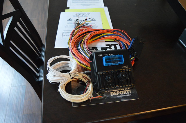
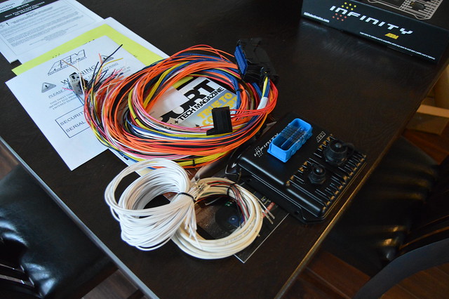
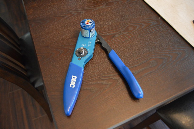
i have flipped over my current stuff to flickr but not sure if i will get around to converting the entire thread over. May do a cliff notes version and answer questions if there are any. Anyways, just got my infinity 506 stand alone and found a crazy deal on the DMC crimper i need for the pins in the milspec connector i will be ordering shortly. It is consistently 100*+ in my garage which makes it hard to find motivation to work on this thing. I have reinstalled my engine harness and the chassis harness so now just planning things out and getting ready for final wiring. Still need to order some battery cable, wire strippers, and another crimp tool for battery cable lugs and the infinity connector plugs. This weekend i hope to get the hood cut for the exhaust and do a mock up on ECU location to confirm the harness length.
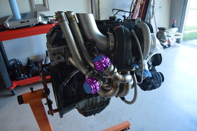
Here is a quick run through to get us caught up from when she came back from the fab shop.
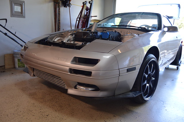
before moving to texas
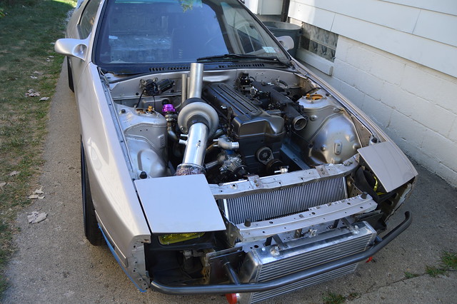
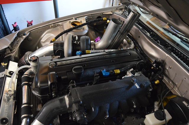
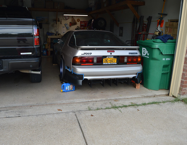
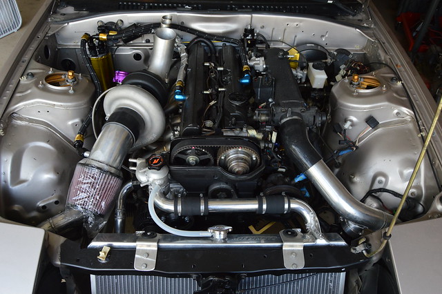
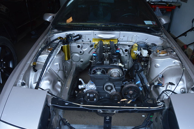
Right when she got back
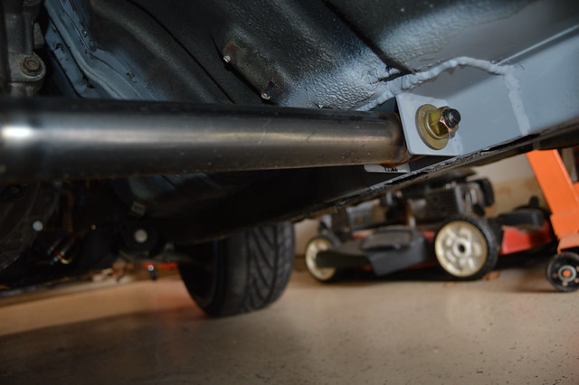
engine mounts got shortened which dropped the engine almost an inch.

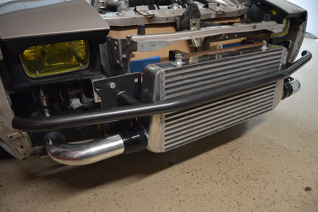
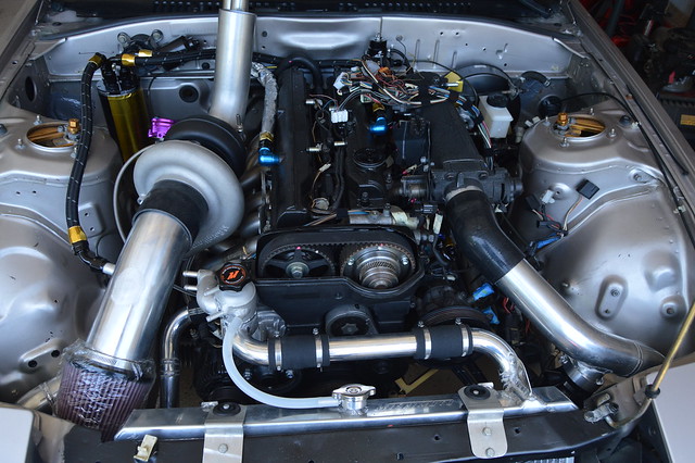
IC setup
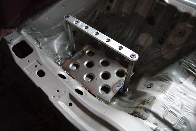
Battery tray setup
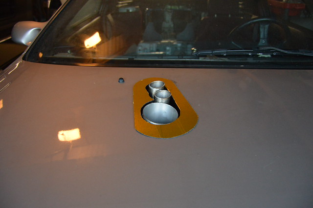
Exhaust welded and catch can mounted
Hood now closes without the throttle body on
i have flipped over my current stuff to flickr but not sure if i will get around to converting the entire thread over. May do a cliff notes version and answer questions if there are any. Anyways, just got my infinity 506 stand alone and found a crazy deal on the DMC crimper i need for the pins in the milspec connector i will be ordering shortly. It is consistently 100*+ in my garage which makes it hard to find motivation to work on this thing. I have reinstalled my engine harness and the chassis harness so now just planning things out and getting ready for final wiring. Still need to order some battery cable, wire strippers, and another crimp tool for battery cable lugs and the infinity connector plugs. This weekend i hope to get the hood cut for the exhaust and do a mock up on ECU location to confirm the harness length.
Here is a quick run through to get us caught up from when she came back from the fab shop.
before moving to texas
Right when she got back
engine mounts got shortened which dropped the engine almost an inch.
IC setup
Battery tray setup
Exhaust welded and catch can mounted
Hood now closes without the throttle body on
Last edited by dandoe; 07-21-17 at 07:34 PM.
07-21-17, 07:30 PM
#62
Full Member
Thread Starter
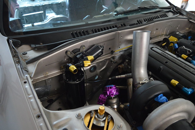
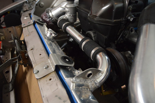
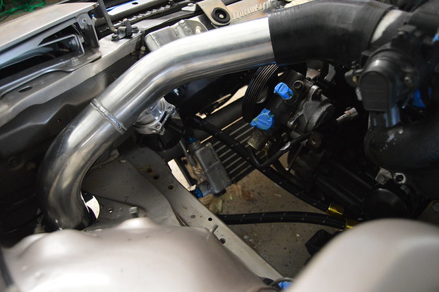
This was the solution to the broken alternator mount ear on the block. Also allows adjustment for the belt tension

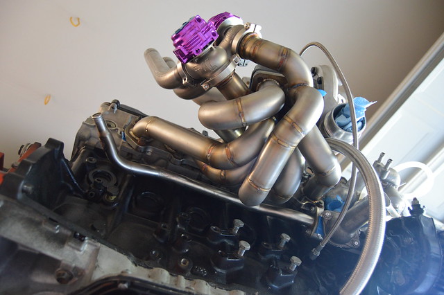
Time for some plumbing
Throttle body cut to delete the traction control motor/ throttle blade
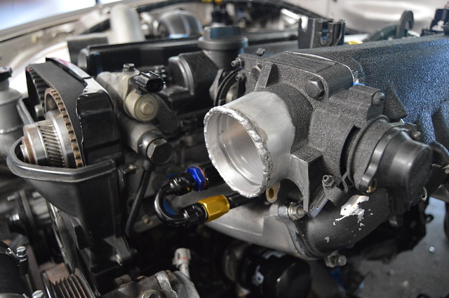
Time for some plumbing
Throttle body cut to delete the traction control motor/ throttle blade
Last edited by dandoe; 07-21-17 at 07:36 PM.
07-21-17, 07:41 PM
#63
Full Member
Thread Starter
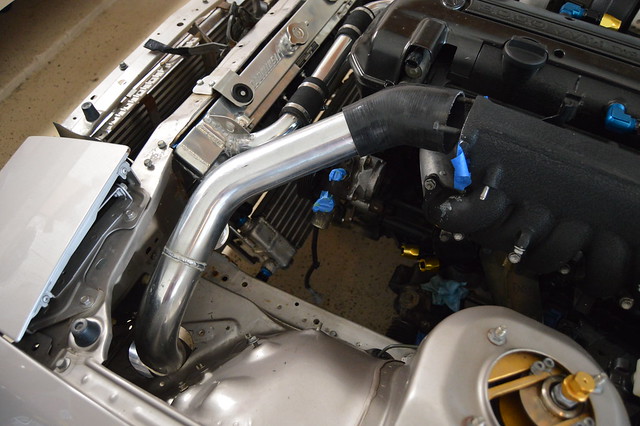
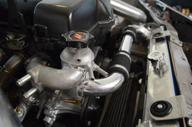
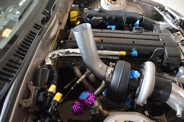
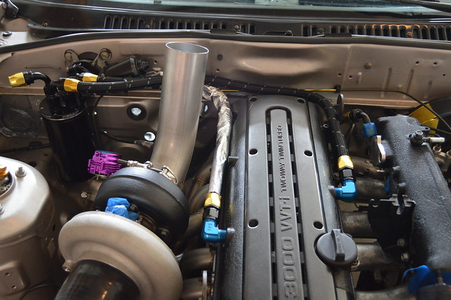
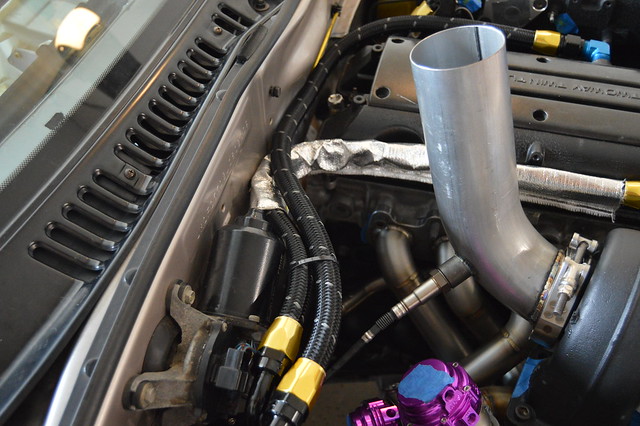
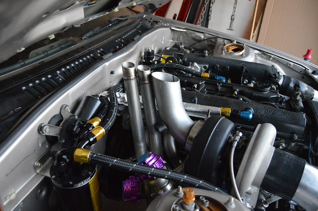
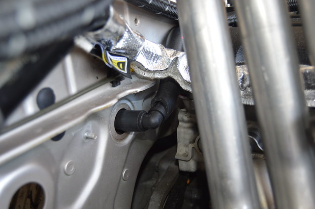
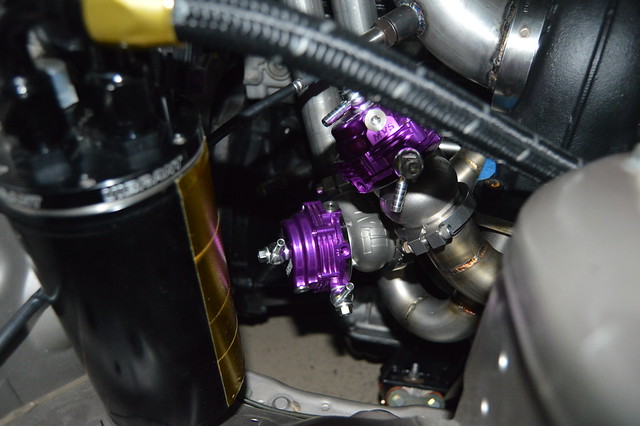
FPR and IAC plumbed in
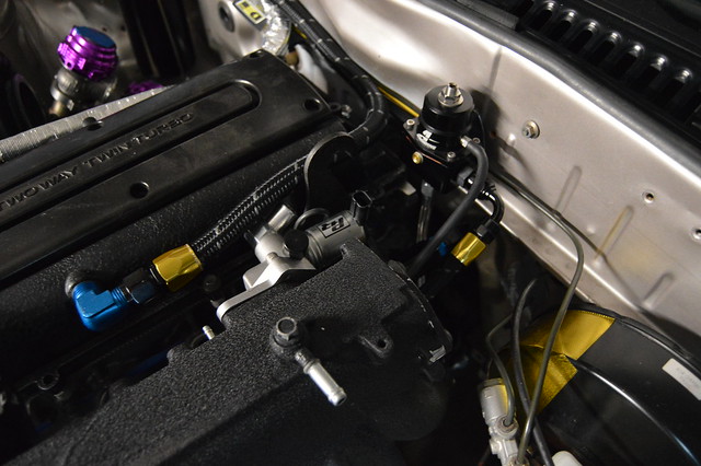
Much better clearance on that feed line now
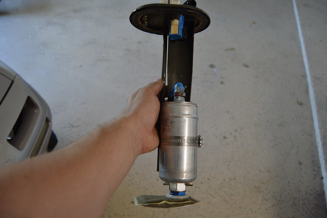
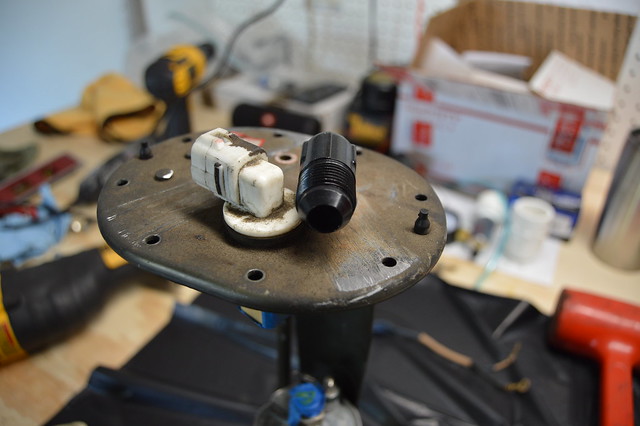
044 mounted and set at the OEM depth
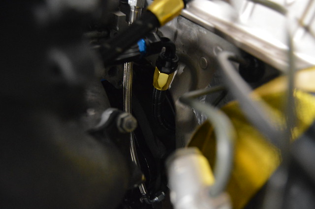
-8 feed mounted, need more fittings to finish this up for good
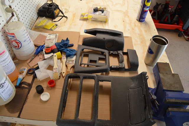
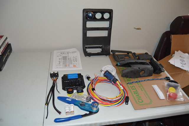
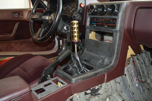
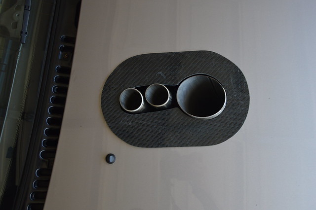
I have a badass 3 gauge air vent pod coming and once that gets fitted i will paint all the trim
Excited to get started on wiring this thing up
Cut up that BN replica rear bumper after selling the skirts and front. Will figure out mounting and remake another set of skirts along with a lip of some type in the front
Much better clearance on that feed line now
044 mounted and set at the OEM depth
-8 feed mounted, need more fittings to finish this up for good
I have a badass 3 gauge air vent pod coming and once that gets fitted i will paint all the trim
Excited to get started on wiring this thing up
Cut up that BN replica rear bumper after selling the skirts and front. Will figure out mounting and remake another set of skirts along with a lip of some type in the front
07-22-17, 10:28 PM
#64
Full Member
Thread Starter
got some stuff done today even though it was hot as hell. 97* in the garage all day but it wasnt too bad.
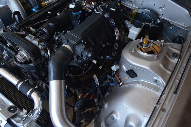
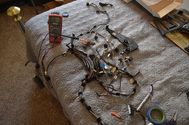
Wiring mess in the bay currently
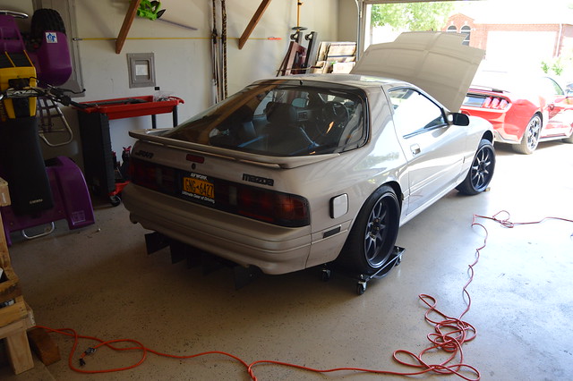
getting pretty good at pulling the hood off and putting it back on by myself lol. No turning back after this!
Cut up this piece of scrap carbon but will be remaking this.
trimmed more of the skeleton and now it clears the throttle body and closes without hitting anything. very happy i dont need to add a vent.

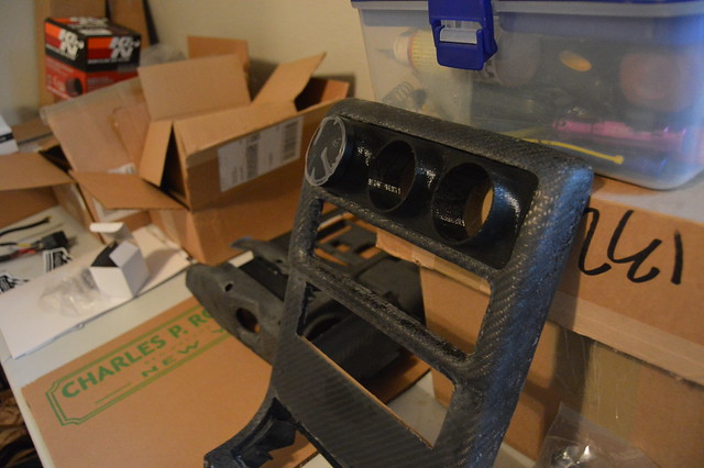
Got this badass 3d printed triple gauge pod from a guy off the RX7 FB group.
Ordered a 55 pin milspec connector lastnight and still need to order some other wiring stuff and sensors before i can get started on the harness. I think i will be wiring in a flex fuel sensor while im at it as well.
Wiring mess in the bay currently
getting pretty good at pulling the hood off and putting it back on by myself lol. No turning back after this!
Cut up this piece of scrap carbon but will be remaking this.
trimmed more of the skeleton and now it clears the throttle body and closes without hitting anything. very happy i dont need to add a vent.
Got this badass 3d printed triple gauge pod from a guy off the RX7 FB group.
Ordered a 55 pin milspec connector lastnight and still need to order some other wiring stuff and sensors before i can get started on the harness. I think i will be wiring in a flex fuel sensor while im at it as well.
07-30-17, 10:25 AM
#65
Full Member
Thread Starter
So looks like photobucket is now supporting third party stuff again? Must have realized what a shitstorm they created. regardless i wont be supporting them anymore and sticking with flickr which is 10X easier to use. Guess now i have to fix all the deleted pics on this page.
Found a smoking deal on this DMC crimp tool setup on ebay.

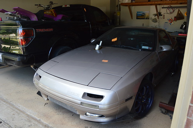
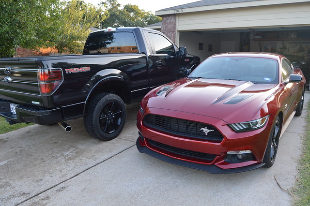
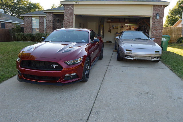
Washed up the rest of the fleet
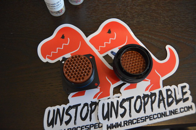
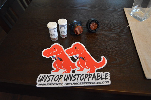
And got my connector kit in. Now i need to order up a fuel pressure, oil pressure, and ethanol content sensor then finish up planning out the harness and get to work.
Found a smoking deal on this DMC crimp tool setup on ebay.
Washed up the rest of the fleet
And got my connector kit in. Now i need to order up a fuel pressure, oil pressure, and ethanol content sensor then finish up planning out the harness and get to work.
07-30-17, 08:53 PM
#66
Full Member
Thread Starter
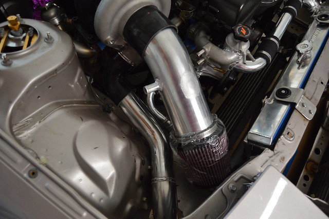
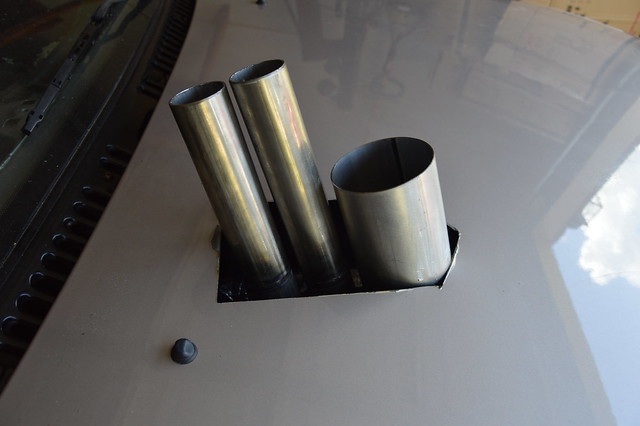
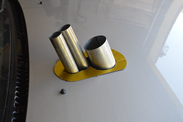
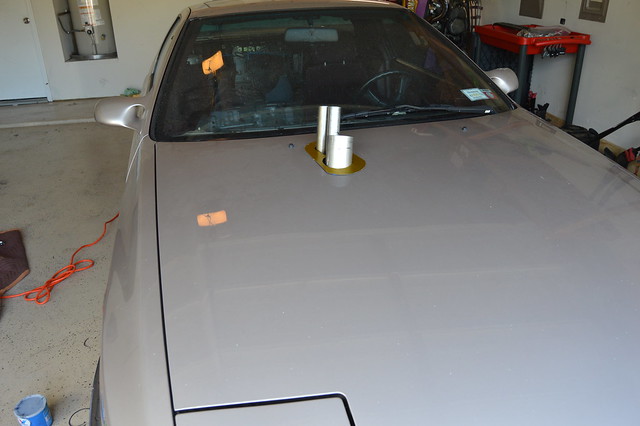
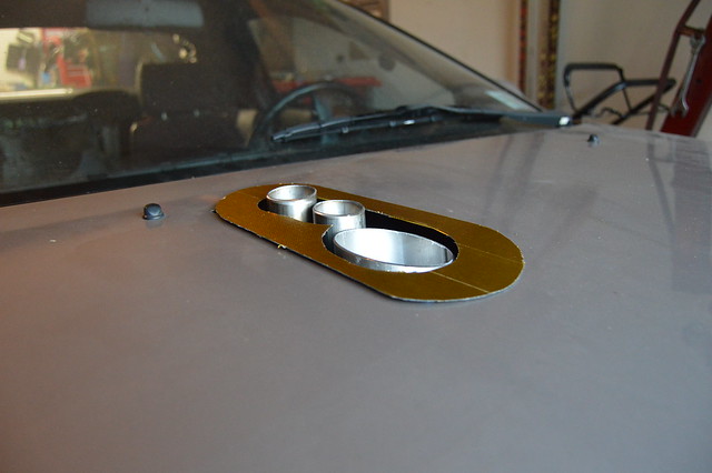
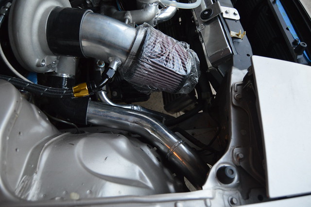
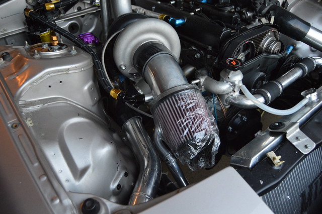
Didn't do much this weekend as i was helping a buddy with his half mile car. Did get a chance to use his chop saw to cut my dump tubes/ exhaust. Now i need to trim the hood a bit more to clock the exhaust to the left and then remake a shroud! Chopped the intake also to run a 7 inch by 6 inch filter as this one seemed disproportionate. intake needs a -10 bung and the IAT sensor bung too.
08-12-17, 07:35 PM
#67
Full Member
Thread Starter
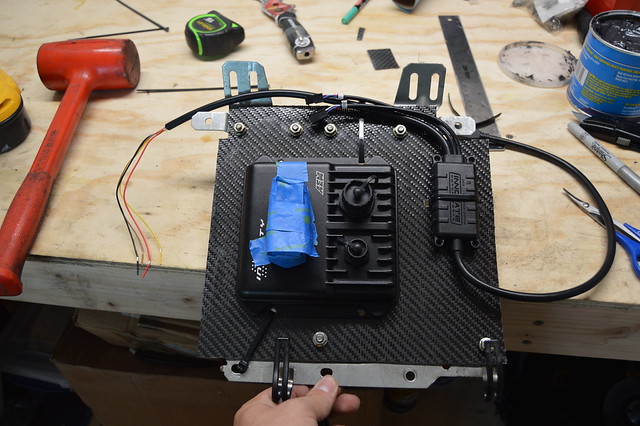
did some planning for the harness build. Whipped up an excel sheet with the connector face views and lists of all the pinouts. Need to start cross referencing my engine harness and ecu pinouts and group stuff together. Still need to get the ecu mounted but im tying to find some alumalite locally to mount the ecu and fuse box/relays. Also have to save up to order all my sensors which includes fuel pressure, oil pressure, oil temp, ethanol content, IAT, and a 5 bar MAP.
Cleared up the table to layout the harness
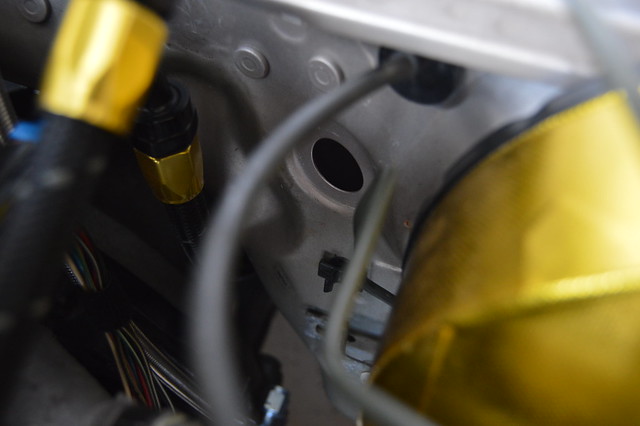
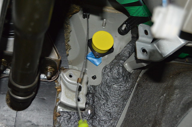
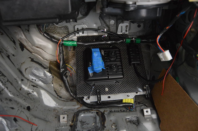
Current plan is to mount the ECU in the stock ecu location and run the harness behind the heater core box
I hope to be able to run it through the current hole shown below. I will likely use a 90* boot on the flange connector. Going to cut that lower HVAC case bracket and firewall stud next time i pull out the dash
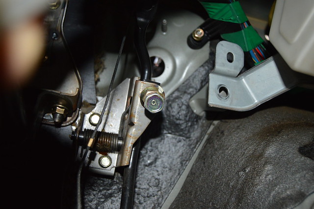
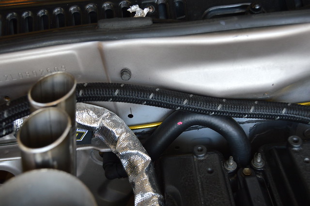
engine side,
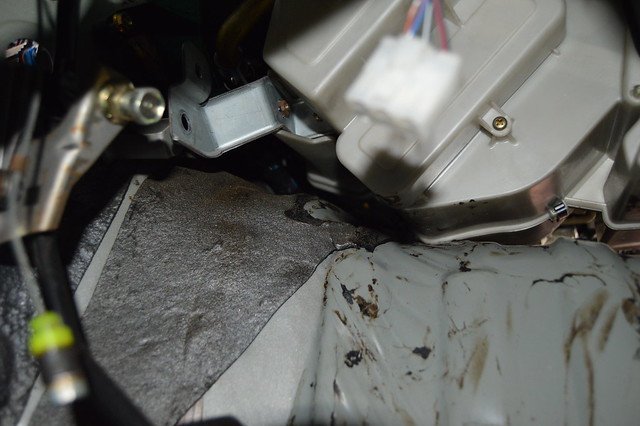
Before putting the dash back in i finished up the heater core lines
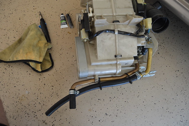
(have to cut that line flush)
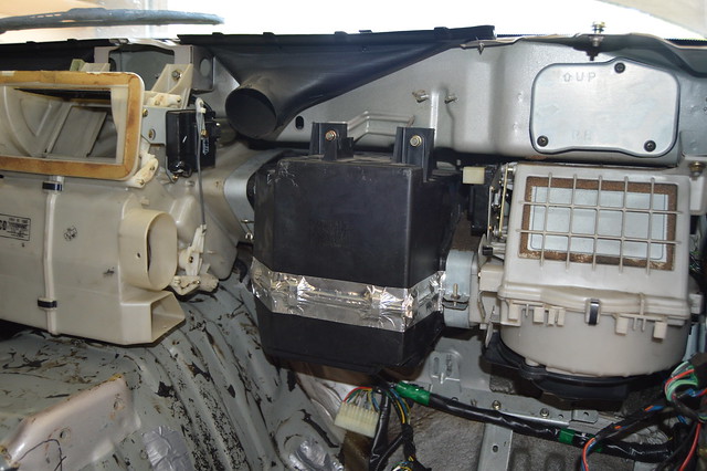
and pulled the evap core then sealed up the box
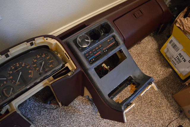
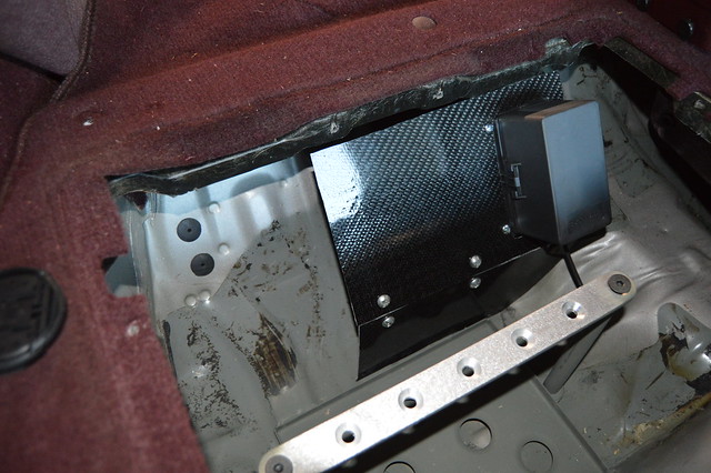
Dash back in to confirm harnes routing, then had to throw all my carbon bits on :bacon:
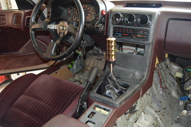
Really wish i didnt impulse cut the dash lastime it was all together as i was able to trim the lower red trim piece and it fit pretty good

Its been too hot lately to clear coat everything but thats low priority
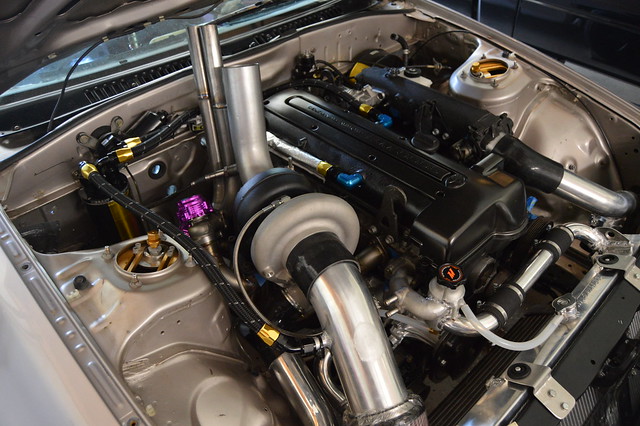
And one of the bay
Cleared up the table to layout the harness
Current plan is to mount the ECU in the stock ecu location and run the harness behind the heater core box
I hope to be able to run it through the current hole shown below. I will likely use a 90* boot on the flange connector. Going to cut that lower HVAC case bracket and firewall stud next time i pull out the dash
engine side,
Before putting the dash back in i finished up the heater core lines
(have to cut that line flush)
and pulled the evap core then sealed up the box
Dash back in to confirm harnes routing, then had to throw all my carbon bits on :bacon:
Really wish i didnt impulse cut the dash lastime it was all together as i was able to trim the lower red trim piece and it fit pretty good
Its been too hot lately to clear coat everything but thats low priority
And one of the bay
08-12-17, 07:36 PM
#68
Full Member
Thread Starter
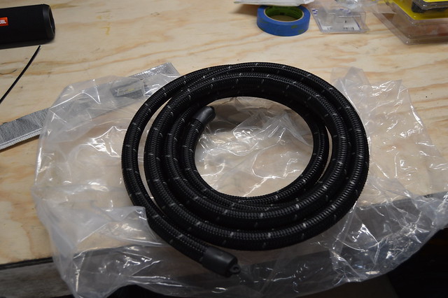
So been trying to get another fuel line/fitting order together to finish up my system. Does anyone know of any braided line that is submersible for my pump plumbing? Everything PTFE doesn't state its submersible and i done want something ghetto with rubber line and hose clamps. Toying with the idea of doing hardlines but then i would have to buy the 37* flare tool as well which gets pretty costly.
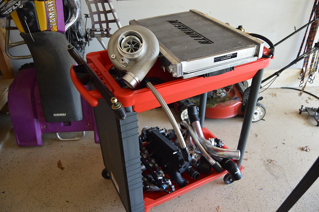
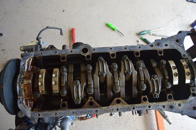
Got a lot done today despite the heat. Pulled the engine to install a new rear main seal and then to reseal the pan as i did not replace the pickup o ring and it was worrying me. Next weekend it will go back in along with the clutch/flywheel and hopefully that will be the last time.
one expensive service cart !
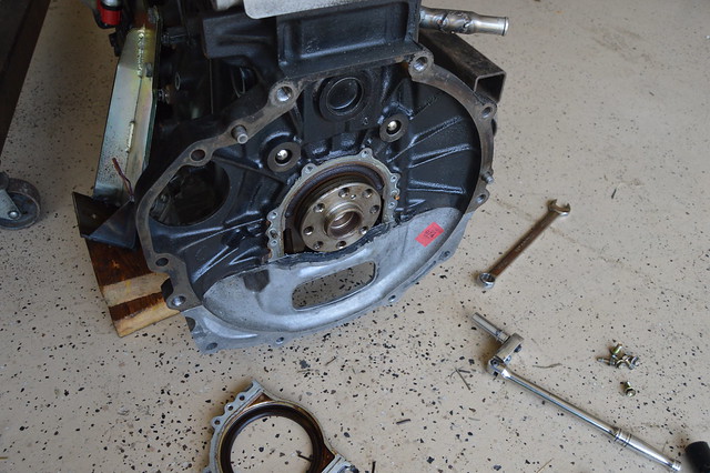
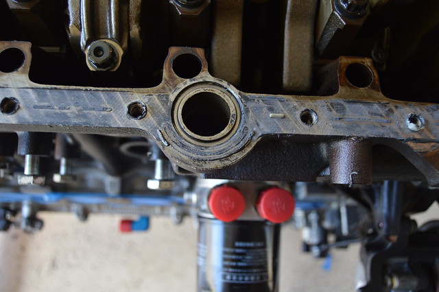
This is the O ring which seals the upper pan to the block for the pickup tube.
and all back together
I need to plug a few coolant ports on the block and the second turbo oil feed before the engine can go back in. Also need to press the larger throwout bearing onto the sleeve and then slap the flywheel and clutch on. Once thats in, i need a driveshaft and clutch line/ master cylinder and drivetrain should be all squared away. going to mount the bulkhead connector sometime this week as well.
Got a lot done today despite the heat. Pulled the engine to install a new rear main seal and then to reseal the pan as i did not replace the pickup o ring and it was worrying me. Next weekend it will go back in along with the clutch/flywheel and hopefully that will be the last time.
one expensive service cart !
This is the O ring which seals the upper pan to the block for the pickup tube.
and all back together
I need to plug a few coolant ports on the block and the second turbo oil feed before the engine can go back in. Also need to press the larger throwout bearing onto the sleeve and then slap the flywheel and clutch on. Once thats in, i need a driveshaft and clutch line/ master cylinder and drivetrain should be all squared away. going to mount the bulkhead connector sometime this week as well.
08-12-17, 07:37 PM
#69
Full Member
Thread Starter
Spent some time in the garage and got a good amount accomplished lastnight and today.
Trimmed down my exhaust studs and now just need new nuts without a flange on them to mount the manifold completely
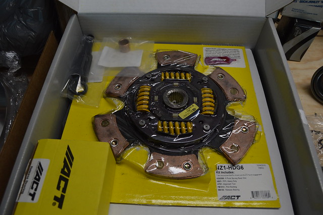
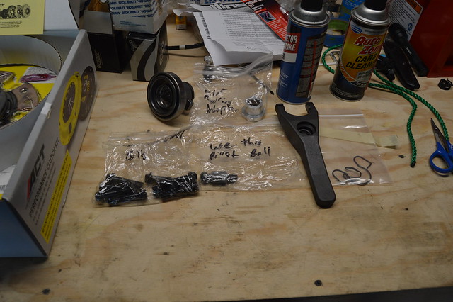
Clutch all ready to go in along with the accessories from the collins kit.
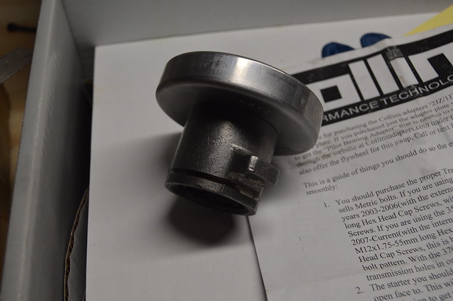
Heres the throwout bearing adapter with the ACT supplied bearing which was about 1/2" larger than the collins one.
I ordered the cast clutch fork and new clips from z1motorsports
Flywheel on and adapter plate torqued to spec
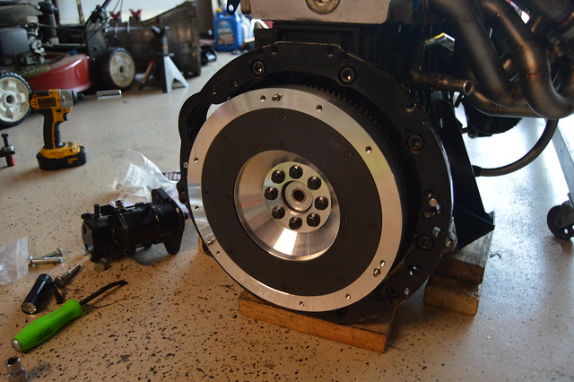
Clutch on and ready for the trans. i should have stopped here lastnight but kept going which led to alot of cursing and frustration
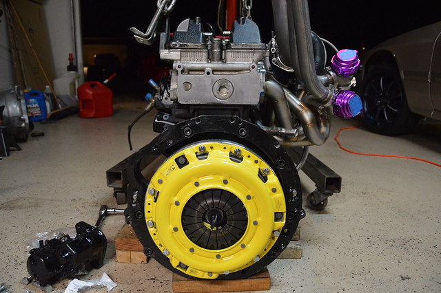
so this is where it went wrong. i could not get the trans to slide all the way onto the engine and was about 1/2" short. I struggled for about an hour then got it close enough to pull it on with the bolts. I then realized that there was no play in the clutch fork and it was sitting on the case yet i could engage it using a large prybar. I went to bed and realized later that night that the pivot ball is preventing the clutch from disengaging all the way.
Here is the longer pivot i got from collins with his instructions.
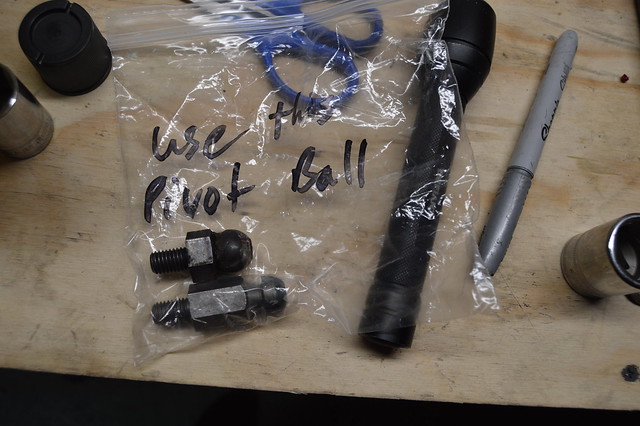
I ended up calling him today (saturday) to confirm that i should use the short one. After explaining my setup and telling him i had the long one installed, his response was simply "why". No complaints as this is the second time i have called him and he led me in the right direction (first one was about clutch master cylinder size which he recommended 5/8"), just was confused why the wrong one was supplied.
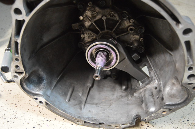
Anyways, after swapping the short one back in, the trans slid right on first try.
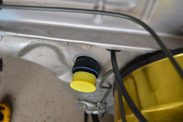
enlarged the hole in the firewall and then mocked up the connector. Might have to space the APP out a bit but it fits good.
Trimmed down my exhaust studs and now just need new nuts without a flange on them to mount the manifold completely
Clutch all ready to go in along with the accessories from the collins kit.
Heres the throwout bearing adapter with the ACT supplied bearing which was about 1/2" larger than the collins one.
I ordered the cast clutch fork and new clips from z1motorsports
Flywheel on and adapter plate torqued to spec
Clutch on and ready for the trans. i should have stopped here lastnight but kept going which led to alot of cursing and frustration
so this is where it went wrong. i could not get the trans to slide all the way onto the engine and was about 1/2" short. I struggled for about an hour then got it close enough to pull it on with the bolts. I then realized that there was no play in the clutch fork and it was sitting on the case yet i could engage it using a large prybar. I went to bed and realized later that night that the pivot ball is preventing the clutch from disengaging all the way.
Here is the longer pivot i got from collins with his instructions.
I ended up calling him today (saturday) to confirm that i should use the short one. After explaining my setup and telling him i had the long one installed, his response was simply "why". No complaints as this is the second time i have called him and he led me in the right direction (first one was about clutch master cylinder size which he recommended 5/8"), just was confused why the wrong one was supplied.
Anyways, after swapping the short one back in, the trans slid right on first try.
enlarged the hole in the firewall and then mocked up the connector. Might have to space the APP out a bit but it fits good.
08-12-17, 07:38 PM
#70
Full Member
Thread Starter
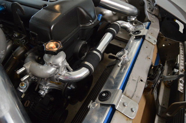
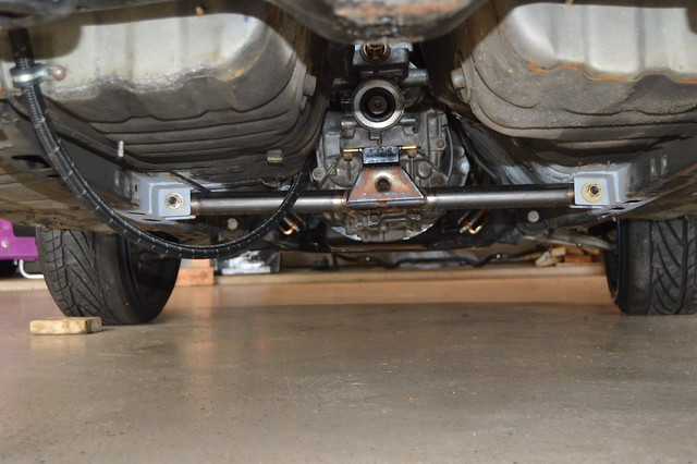
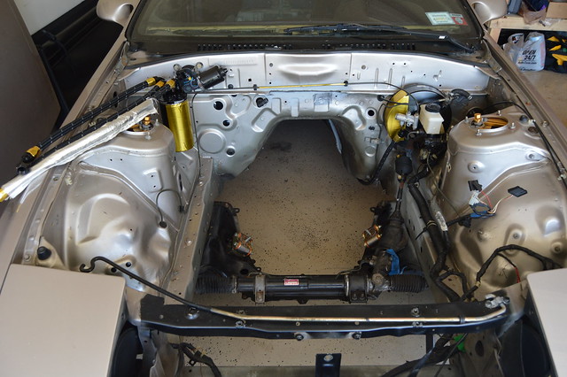
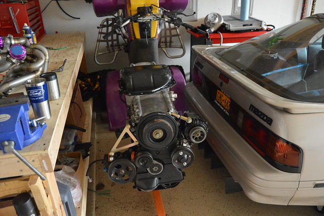
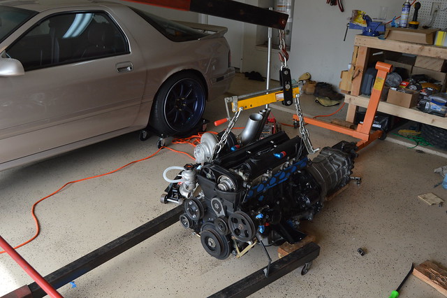
Threw the engine back in and got everything torqued down to measure the drive shaft length
Called the driveshaftshop in NC and they told me to measure from output shaft to diff flange with the wheels on the ground and send them the measurements for a quote. I measured first with a measuring tape and got 32 3/8"- 32 1/2". Just to confirm i used this paper measuring tape and folded it on each side which yielded me 32 1/2" so thats what i will be giving them.
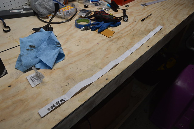
Called the driveshaftshop in NC and they told me to measure from output shaft to diff flange with the wheels on the ground and send them the measurements for a quote. I measured first with a measuring tape and got 32 3/8"- 32 1/2". Just to confirm i used this paper measuring tape and folded it on each side which yielded me 32 1/2" so thats what i will be giving them.
09-10-17, 04:59 PM
#71
Full Member
Thread Starter
update time. Been trying to use up all this resin ive had for 4 years so started off with a sheet, 1 layer of woven fiberglass mat then a layer of carbon. didn't care too much about looks here just strength and function in this case.
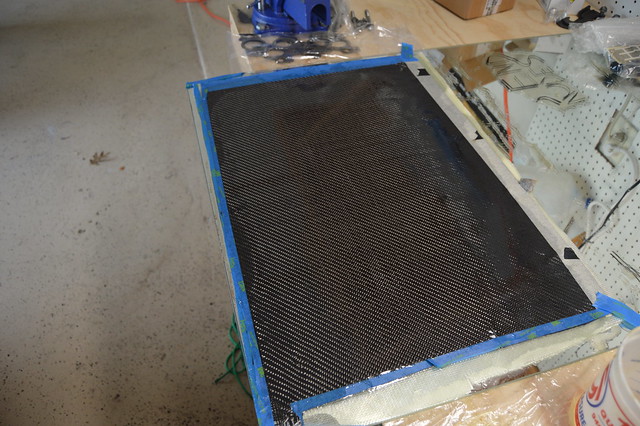
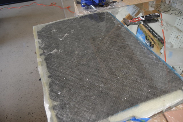
Proceeded to turn it into this..
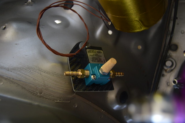
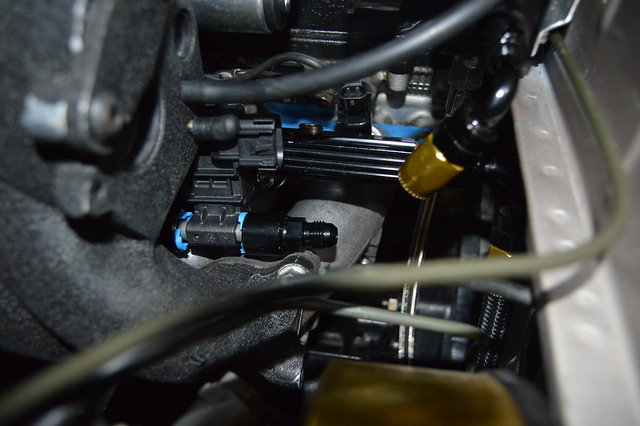
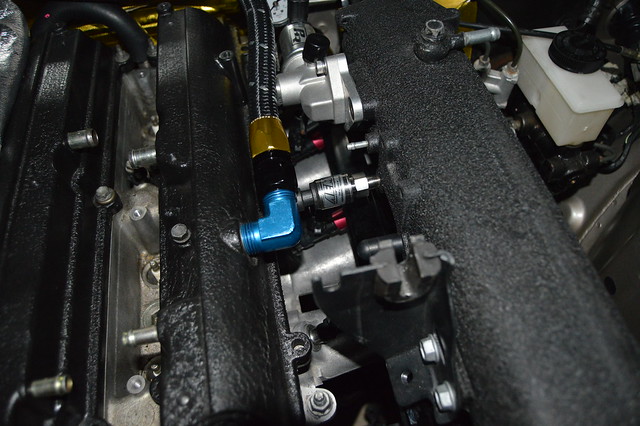
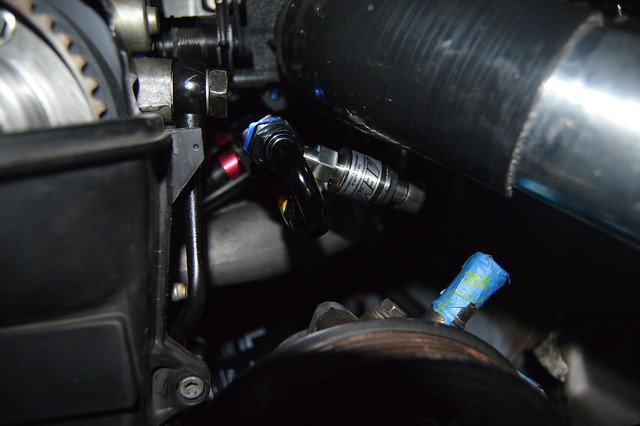
Got my fuel pressure sensor, ethanol content sensor, and MAP sensor installed. Need one more 45* fitting to finish up my return line.
Got wastegate vacuum line routing all planned out.
Proceeded to turn it into this..
Got my fuel pressure sensor, ethanol content sensor, and MAP sensor installed. Need one more 45* fitting to finish up my return line.
Got wastegate vacuum line routing all planned out.
09-10-17, 05:00 PM
#72
Full Member
Thread Starter
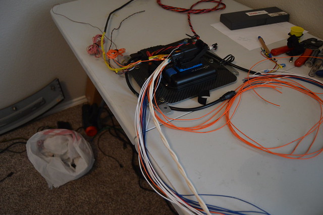
Then got started on wiring after figuring out my harness length. Ended up making this depinning tool for $2 as opposed to the $50+ dollar molex one.
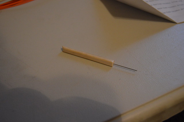
this allowed me to move some circuits around to add my inputs.
Shortened the o2 sensor harness and ready for some heatshrink
then got to work indexing the engine side and figuring out some 5V and signal ground routing.
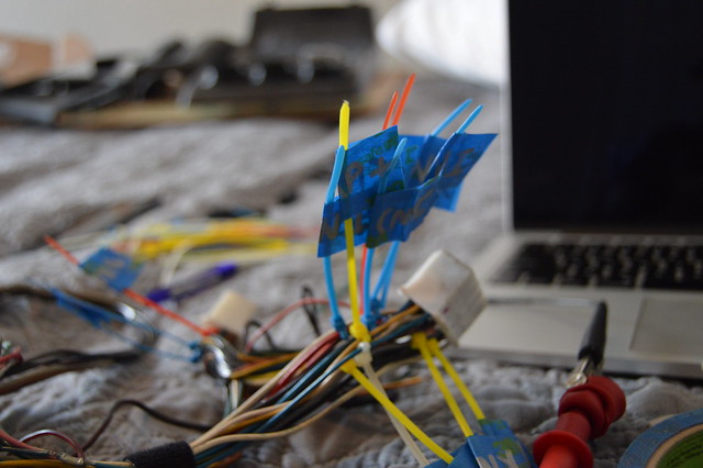
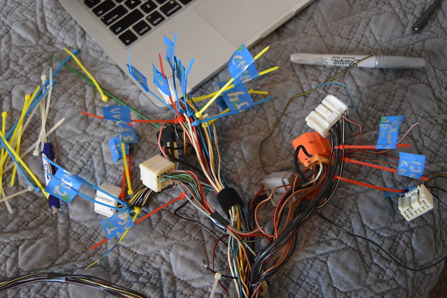
using the wilbo666 wiring pinouts i was able to identify everything i will need.
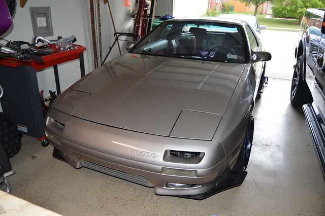
then rolled her out of the garage and washed all the junk off
Got the power/ground and relay control side of my harness separated from the engine control side and now waiting on some shielding splices so i can finish the ecu connector side up then start twisting and terminating the bulkhead connector.
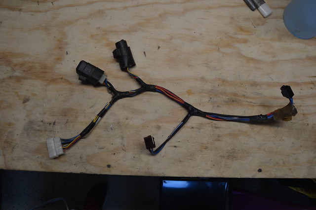
Getting my fuse box started once they ship me the correct one. have all the wiring for that and ordered two more crimp tools for the metripack stuff. does anyone know what this harness is for? i had it separated with the HVAC stuff but dont remember where it came from.
Once i get the cabin side of the harness terminated i will start with adding the wiring for all my new sensors on the engine side. Still have to get the IAT bung welded in at the charge pipe, -10 AN bung for the breather system, and the second o2 sensor welded up. I also will be running an IGN1A ignition setup which i have to order up along with my driveshaft.
this allowed me to move some circuits around to add my inputs.
Shortened the o2 sensor harness and ready for some heatshrink
then got to work indexing the engine side and figuring out some 5V and signal ground routing.
using the wilbo666 wiring pinouts i was able to identify everything i will need.
then rolled her out of the garage and washed all the junk off
Got the power/ground and relay control side of my harness separated from the engine control side and now waiting on some shielding splices so i can finish the ecu connector side up then start twisting and terminating the bulkhead connector.
Getting my fuse box started once they ship me the correct one. have all the wiring for that and ordered two more crimp tools for the metripack stuff. does anyone know what this harness is for? i had it separated with the HVAC stuff but dont remember where it came from.
Once i get the cabin side of the harness terminated i will start with adding the wiring for all my new sensors on the engine side. Still have to get the IAT bung welded in at the charge pipe, -10 AN bung for the breather system, and the second o2 sensor welded up. I also will be running an IGN1A ignition setup which i have to order up along with my driveshaft.
09-16-17, 04:49 PM
#74
Full Member
Thread Starter
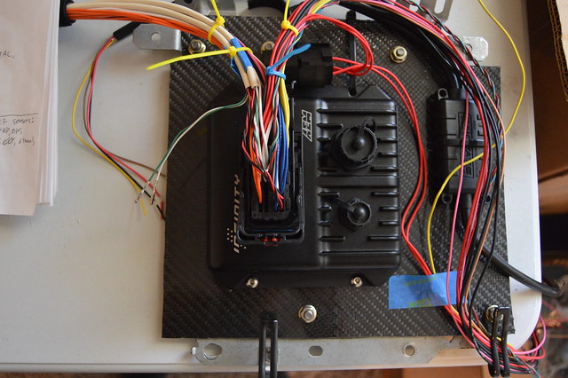
Thanks, i am trying lol. Speaking of wiring....
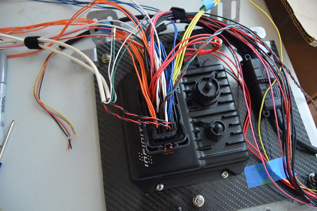
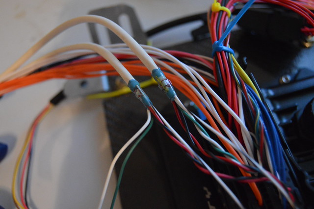
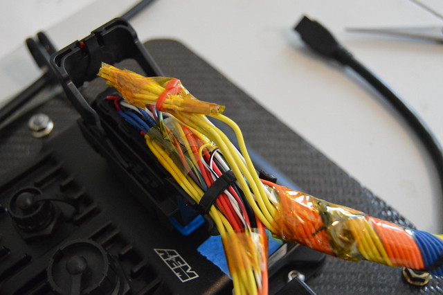
Big wiring update! i have been planning everything out and making sure i have the majority of what i need before starting with this. First needed the shielded cable solder splices to properly ground my shielded cable. I am using the AEM supplied 4 core cables, two circuits for CKP and CMP each, then 2 more for both knock sensors. This leaves me with 2 extra circuits for use in the future. These splices are lined up with the shielded cable so it can be grounded properly.
With that being the last piece of the puzzle on the ECU side i zip tied that up.
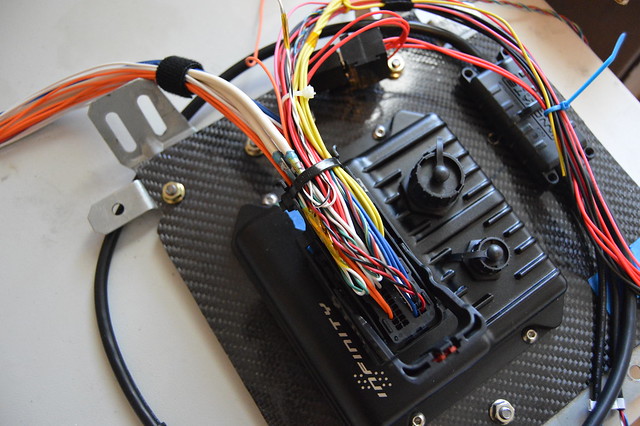
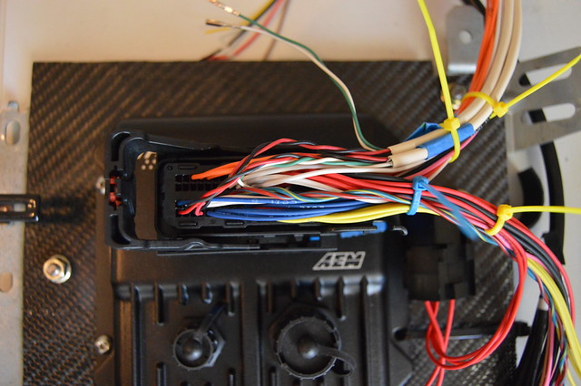
Now i have the harness separated into a power/ground/ 12V switched loom, a wideband/ boost control solenoid loom, a CAN/ 2 step switch/ shield ground/tach loom, and an engine input/output loom. Twisted up the power/ground side which will run to my fuse box/battery
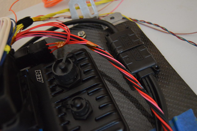
Ready for heatshrink and a deutsch connector
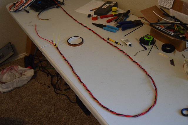
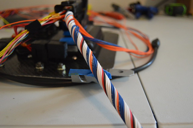
Started the main engine harness with twisting the shielded cables which will be my core here
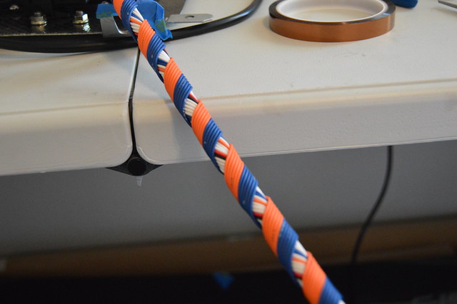
Now typically you want to wrap layers of 6 at a time and because i have 26 total circuits after the shielded wires i wrapped 2 with the core.
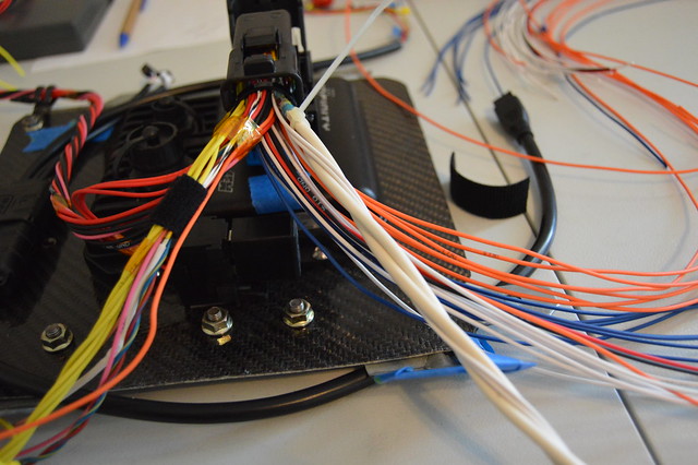
First layer of 6
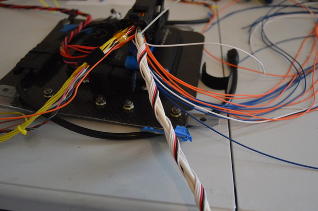
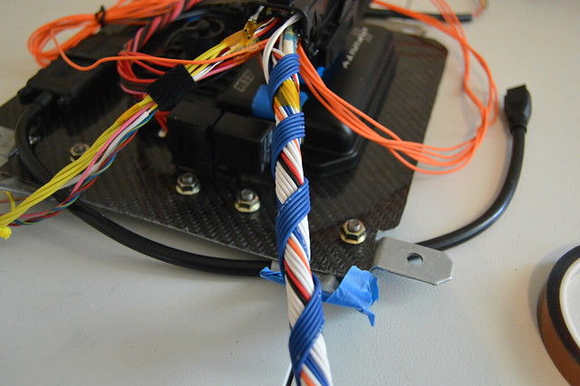
Second layer of 6
Third layer of 2 filler wires (someone didnt plan correctly)
Big wiring update! i have been planning everything out and making sure i have the majority of what i need before starting with this. First needed the shielded cable solder splices to properly ground my shielded cable. I am using the AEM supplied 4 core cables, two circuits for CKP and CMP each, then 2 more for both knock sensors. This leaves me with 2 extra circuits for use in the future. These splices are lined up with the shielded cable so it can be grounded properly.
With that being the last piece of the puzzle on the ECU side i zip tied that up.
Now i have the harness separated into a power/ground/ 12V switched loom, a wideband/ boost control solenoid loom, a CAN/ 2 step switch/ shield ground/tach loom, and an engine input/output loom. Twisted up the power/ground side which will run to my fuse box/battery
Ready for heatshrink and a deutsch connector
Started the main engine harness with twisting the shielded cables which will be my core here
Now typically you want to wrap layers of 6 at a time and because i have 26 total circuits after the shielded wires i wrapped 2 with the core.
First layer of 6
Second layer of 6
Third layer of 2 filler wires (someone didnt plan correctly)
09-16-17, 04:49 PM
#75
Full Member
Thread Starter
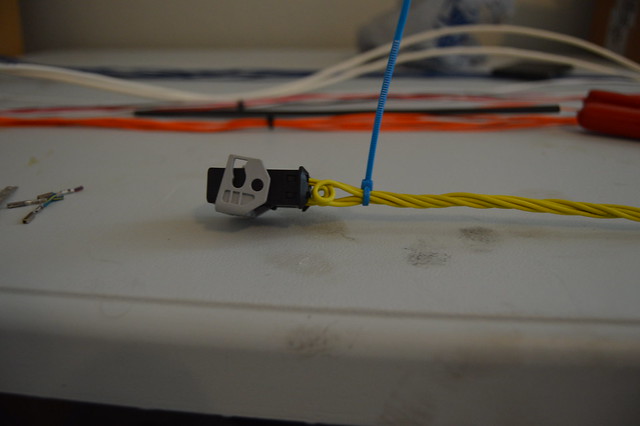
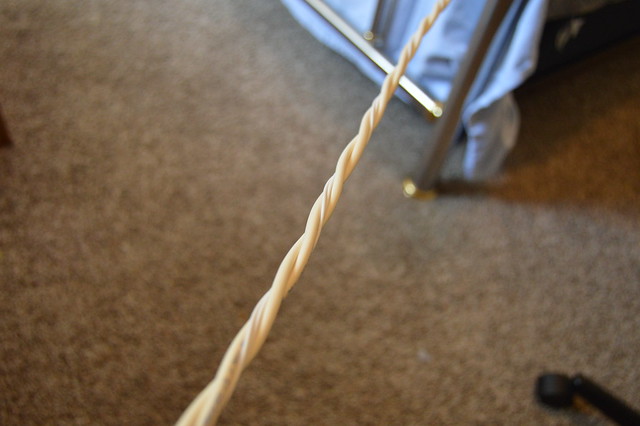
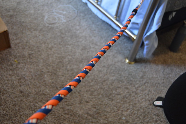
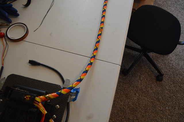
Third layer of 6 going the other direction now
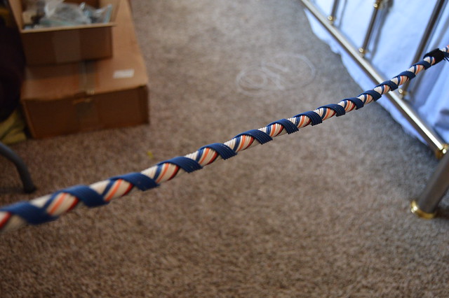
Fourth layer of 6
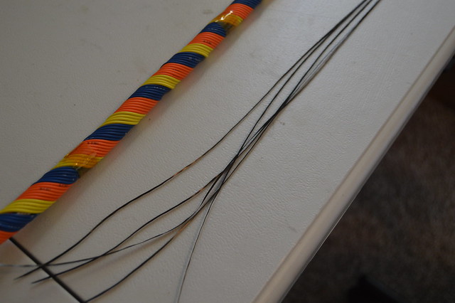
So the industry correct way to concentric twist a harness is to cut all your wire to length (+20%) and then start in the middle and work your way out. It should be done one layer clock wise, then one layer counter clock wise and repeat. Since i have my ECU side terminated already this method cannot be used so i had to do two layers clock wise then 2 counter, and so on. I also had an odd number of total circuits due to the core being large with 8 circuits total (from shielded cable). This left me with needing to use filler wires so after this last orange layer i needed to add an additional layer of 4 more circuits (yellow) to fully fill it out. I do not personally think this is a big deal as i now have 6 extra circuits that i can terminate on both ends without cutting open the harness for future expansion.
I did not take many pictures as it got very difficult to keep the end wound tight while taping and wrapping the last layer. I also cheaped out on spending $30 on a 1500 yard roll of lacing cord so i pulled threads out of the rolls of raw carbon fiber i have.
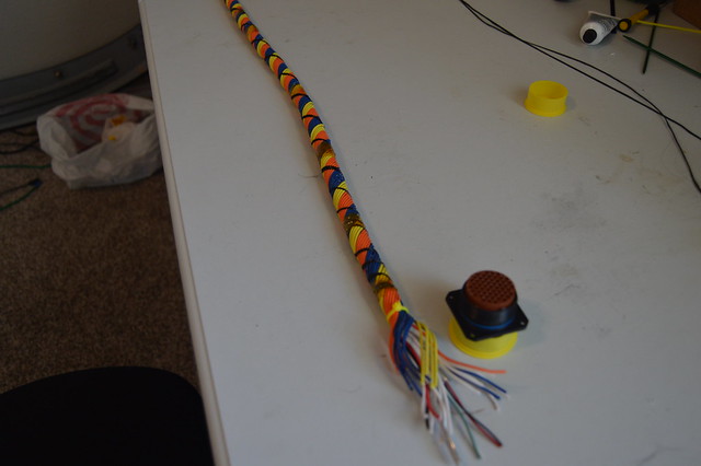
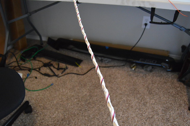
6 filler circuits pinned on the ECU side and wrapped in kapton tape
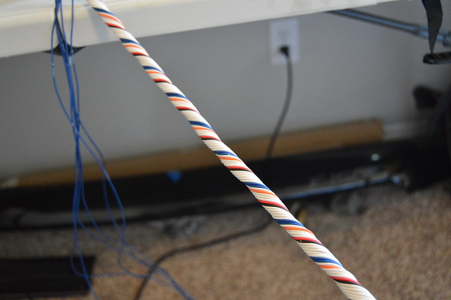
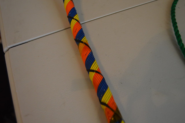
All done and perfect length now awaiting heatshrink. This is a 40 circuit total with two 4 conductor shielded wire bundles core measuring .55" in total diameter. I am pretty happy with how this came out for it being my first time. I will be running the modified OEM harness on the engine side but now want to badly build a harness from scratch with new toyota connectors over the winter. This should only cost me a few hundred dollars since i am now tooled to do this.
Fourth layer of 6
So the industry correct way to concentric twist a harness is to cut all your wire to length (+20%) and then start in the middle and work your way out. It should be done one layer clock wise, then one layer counter clock wise and repeat. Since i have my ECU side terminated already this method cannot be used so i had to do two layers clock wise then 2 counter, and so on. I also had an odd number of total circuits due to the core being large with 8 circuits total (from shielded cable). This left me with needing to use filler wires so after this last orange layer i needed to add an additional layer of 4 more circuits (yellow) to fully fill it out. I do not personally think this is a big deal as i now have 6 extra circuits that i can terminate on both ends without cutting open the harness for future expansion.
I did not take many pictures as it got very difficult to keep the end wound tight while taping and wrapping the last layer. I also cheaped out on spending $30 on a 1500 yard roll of lacing cord so i pulled threads out of the rolls of raw carbon fiber i have.
6 filler circuits pinned on the ECU side and wrapped in kapton tape
All done and perfect length now awaiting heatshrink. This is a 40 circuit total with two 4 conductor shielded wire bundles core measuring .55" in total diameter. I am pretty happy with how this came out for it being my first time. I will be running the modified OEM harness on the engine side but now want to badly build a harness from scratch with new toyota connectors over the winter. This should only cost me a few hundred dollars since i am now tooled to do this.