When you click on links to various merchants on this site and make a purchase, this can result in this site earning a commission. Affiliate programs and affiliations include, but are not limited to, the eBay Partner Network.
Been following this from the beginning. Excellent work so far. It shows a lot of thought and consideration that most people don't put into their wiring.
But, it then puzzles me why you would take the factory path on the right side which runs the harness directly over the hot turbo area. Why not follow along the firewall and break out above the engine? Or even better, what I've been doing lately, just run the harness up to the engine via the transmission tunnel?
Thanks! I sort of like the RH path since i plan to mount some sensors forward of the fender well and the harness gets close so a breakout is easy. That being said you could certainly get there from another split.
Honestly i started down the path of copying the factory harness layout as closely as possible so i could use it as a pattern. My hope was to have as little down time as possible if i could keep the car together while i did the harness. By the time i realized that wasnt feasible or valuable, i was fairly committed to the layout. For the most part i like the factory layout and i know the OEMs put a huge amount of time into engineering that. I see the concern about heat, but there really is a lot of clearance there so heat shouldnt be an issue. There's plenty of other parts with a lower heat tolerance than the milspec harness in that area.
Originally Posted by clokker
I've enjoyed following this even knowing nothing of the art of motorsports wiring.
Could you provide some info on the underlaying theory and practice of the wire twisting?
Obviously it looks bitchin, but I suspect there's aviation influence in play and a more hard-nosed, practical reason for why/how it's done. I'd guess that flexibility/stress relief are major goals of the technique but don't really know.
As a member of the rabble whose harnesses have been frankensteined cut/paste jobs tournequetted in electrical tape, I'd like to appreciate the finer points of your craft.
Originally Posted by ACR_RX-7
From what I understand, concentric wire twisting allows for the smallest diameter of harness given the number of wires. Also, it allows for flexibility in the harness and EMI resistance to the overall harness due to the twisting.
ACR_RX-7, good answer to clokker's question. The one thing i would add, which is related to the flexibility, is that its less likely to over stress a single wire when bent or strained. I made some mistakes on that point in my harness by having splices in the straight runs, that not only looks ugly and doesnt twist as well, but it certainly adds strain to the splices (which are weak points already). Also, using kapton tape instead of lacing cord to hold the twisting in place is much more likely to strain the wires instead of letting them slide relative to one another.
Originally Posted by Nosferatu
thanks for sharing...this is awesome work....what would also be a cool addition and making the harness job easier I suspect would have been a sealed circular firewall connector making it easier to pull and install the motor. Although that would not have been a cheap addition as the connectors are expensive and the crimpers even more ridiculously priced.
Since i have north of 100 wires in that part of the harness it would mean multiple bulkhead connectors. There's also not a great place to mount bulkhead connectors and it would require making new holes in the firewall. There is however a great big hole with a sweet factory grommet that works great and only adds ~20min of work to remove the whole harness. I really hope to not change engines often enough to care about that extra 20min per change.
Thanks for all the comments, sorry for taking so long to respond.
You have one of my favorite builds on here. It's the only one that I've seen recently with a deeper electronics insight than I could ever wish to attain. Stay hungry.
I have a link to my build in the description. Might change your mind on the "keeping it factory hardware" deal.
It's been a while.... I've got plenty of excuses for not making much progress over the last year and a half but basically I've only worked on this project for a day here or an afternoon there. But, I've finally made enough progress recently to be worth updating this.
I've got all the connectors terminated except for the 4 ECU connectors, and I just did another test fit in the car to figure out the final length for those leads. Thankfully it doesnt look like i got anything too short, plenty of leads are on the long side but thats easy enough to deal with. I probably wont shorten anything yet, just tie it up out of the way for now.
Here are some pictures of what I've been up to.
So next up, i have to terminate the ECU connectors. I think i have the hardest part of that done, so there's a chance i could get those done this weekend. Maybe.
Then i will need to do some bench testing to try to make sure everything goes where its supposed to. The exercise of separating the whole trunk into the 4 individual leads for the ECU connectors helped me spot some misplaced wires. Luckily they were easy to deal with at this stage. Along with that will be some software testing to make sure that i can use all the pins as i intend in the software. I havent looked into that too deeply yet, so hopefully i dont get any surprises there.
Then i think if i'm confident with the bench testing i want to boot the harness before installing it in the car. When i test fit it today i was worried about hurting something without having it booted, i certainly untwisted some service loops that i will need to repair.
There are still a few things on the chassis side that i need to put connectors on, namely the crank angle sensor and TPS as well as a few pins from the ECU connector on the chassis loom.
Then there are still some sensors to work out. I need a good air temp sensor, i really want a KA sensor similar to what we run on the racecars, i've been hesitating on buying one since theyre sort of expensive but i think i need to. I also still need to mount my MAP sensor in the manifold, tho i still dont have a great solution for how to do that.
We finally got thru the LeMans push for work so i've had a bit of time to work on the harness this week. I finally got to the point where i plugged it in and fed it 12V and it came alive! no smoke came out so im pretty happy so far. The ECU has a blank firmware so now i need to learn how to use M1 build to do something real with it.
Let me back up a bit and catch up. So i think since the last post the main thing i had to do was install the ECU connectors. Those are surprisingly time consuming. Each one took at least 3 or 4 hours. Pro tip, the connectors are keyed, which i should have known, but like i rookie i got the first one all populated before realizing that it was the wrong one... whoops.
In most cases i spliced the power and grounds externally tho i think they are spliced internally as well. I doubt its required so in the cases where it wasnt easy, i skipped it.
I tried to do service loops on these connectors as well with varying success. Its pretty tough to get them to turn out nicely so kudos to the pros who can. At least what i ended up with will help to strain relieve, even if it isnt pretty.
I ended up with 3 mystery wires when i got all done. I think they are from shielded cables where i wasnt using all conductors in the shield. I left them tied up in the connector in case i ever find a use for them.
The normal pins are pretty easy but most of the time is spent on the unusual things. For instance, in some cases a 3 or 4 wire shielded cable ran to one connector but a couple wires needed to get to another connector. The trickiest of those was the CAN lines where i also added the terminating resistor in the same splice. That means you have 2 unusually routed wires that are tied together at the splice with a resistor and it made for not a very nice blob to try to tuck in amongst the other wires. I'll need to add another post with some more pictures.
The D connector took the better part of a day since i had to deal with terminating 5 shielded cables. I was able to use solder sleeves to tie the shields together and i had 2 wires run back to a 0V pin in the A connector that i wanted them grounded to. So i grouped 2 shields into one wire and the other 3 into another. The trick is getting them all lined up nice so that its still flexible and doesn't have a huge bulge in the line bundle. It certainly has a bulge but came out better than i expected.
I probably could have come up with a better routing of the 4 leads. It's sort of awkward because of the way i separated and twisted the legs on the desk in A-B-C-D order. I really should have done it D-C-B-A i think. Oh well it will work fine.
This is a complete mess but you know how it is when you get close to a big milestone. I was pretty careful with wiring in the 12V though, i had to try hard to stay patient there. I used a longish 22awg wire and a 5 amp fuse. Just in case. Thankfully it all seems good so far. No hotness.
So next up is to learn how to use M1 Build to get a firmware into this thing that i can use to test everything. Once i'm happy with the bench testing i think i want to boot the harness. Then i will need to finish the hardware mods as well as the remaining carside wiring mods. Then install it and test everything in place....
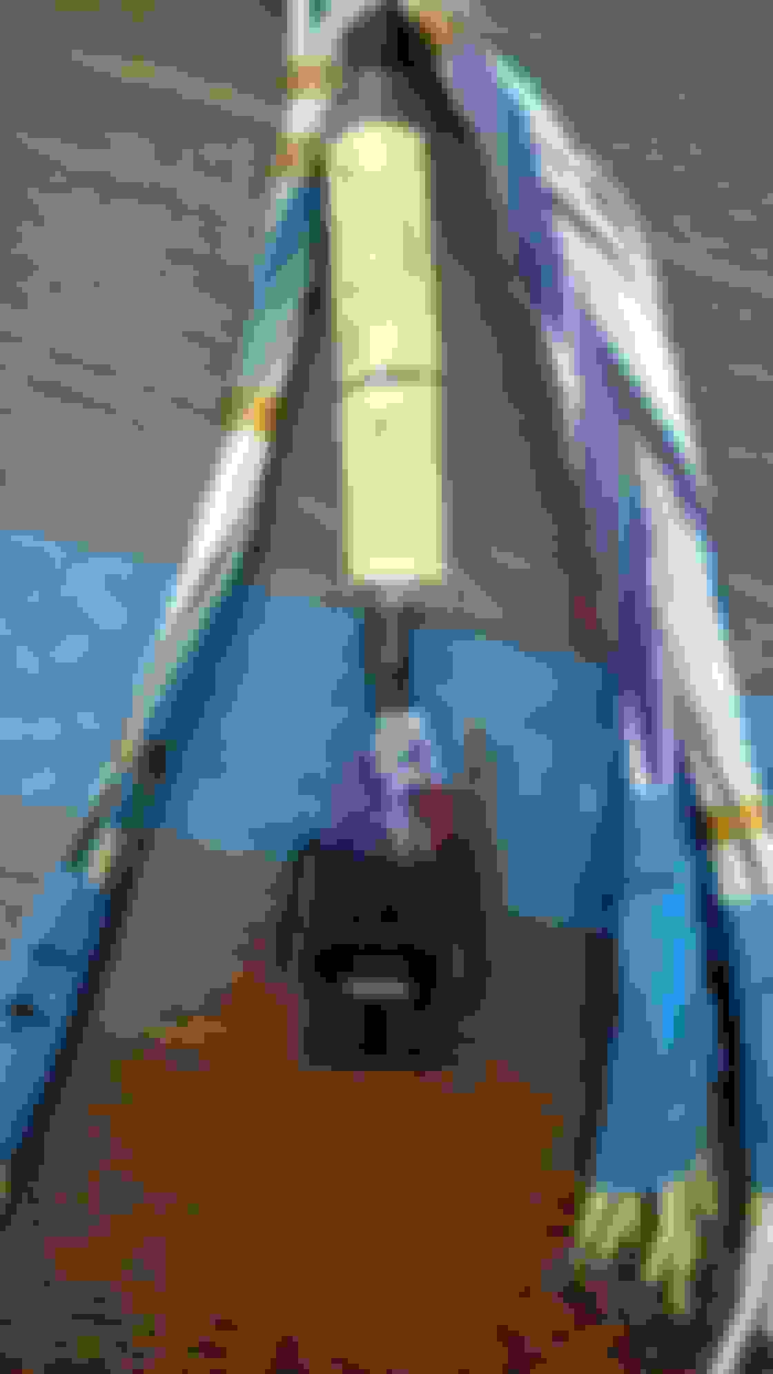
Here are some more pictures to go with the last post.
This was a nightmare to separate.
All separated and twisted.
And then i realized i should have gone D-C-B-A, not A-B-C-D. oh well.
After splicing all the shields in connector D i ended up with a little bulge in the lead, but better than i expected honestly.
I had one wire out of them all that ended up too short at the ECU connector so i had to splice an extension.
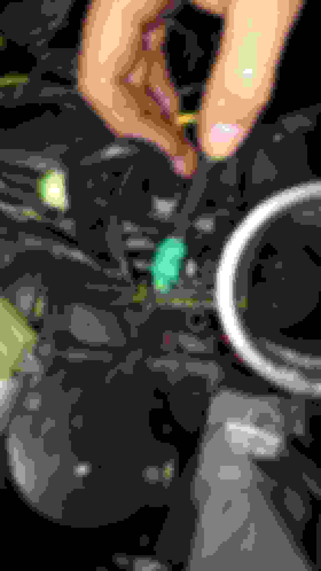
This was round 2 of populating this connector. I should have known they were keyed...
CAN termination resistor. Unfortunately i dont have any 120 Ohm resistors in my stocks so I'm using 100 Ohm. That should be fine for a small bus like this.
Splicing and terminating a CAN bus that had to go back to connector A.
This ended up as an ugly blob, but i guess im not sure how to do it nicer other than to run a separate shielded cable back to the right connector.
connecting to a panel mount RJ45 port for the ethernet comms.
In the interest of time, I've started with the GPR software from Motec. I hope to get it started on that and work my way into a custom software. Currently I'm working thru a starting calibration since currently its blank. I've gotten all the errors cleared so i've finally got it flashed in and started to work on sensor calibrations.
Does anyone have data on the stock calibration handy? Specifically ignition timing, injection timing, and coil dwell times? Those would help save me some time.
Does anyone have any handy tips on knock tuning on a rotary? Namely the knock window ( i assume its a little different than a piston engine).
There's an old SAE paper from Mazda that references the natural knock frequency in a 13B. It's 3.5khz +/- 0.3khz. I'm not sure what knock sensors you're using, but RX8 knock sensors are wideband, but M8 bore. The S5/S6 knock sensors in the housings are M10x1.25, but you can buy an adapter stud from Toyota dealerships to use the RX8 sensor. If you have an S4 block, you're SOL.
Shainiac,
Thanks for the reply and the info. Thats much lower than i am used to from the 4 valve piston engines i normally work with, but with the much different shaped combustion chamber i think its at least directionally correct.
I'll be interested to play around with it some to see if they chose that freq due to limitations in electronics or if that really is the first node natural freq. I wouldnt be surprised if there is a higher node that they weren't able to process well. The M1 has 4 separate band pass filters so you can quickly try a few options. It only controls to 1 freq, but you can log all 4 and do quick comparisons on the same event.
I have a modern Bosch KS type sensor and helicoil'd the stock s4 m10 location to an m8. I think itll work OK, tho i understand that location isnt as nice as a the later engines.
Now i wish i had run a second knock connector in my harness since it sounds like the trick setup would be 2 sensors on the S5 rotor housings...I can at least still get to another knock pin but it will take a jumper harness from a spare connector and be a bit messy.
Any ideas on the knock window? On the piston engines they usually start around 10-15*ATDC but i expect that will be different on a rotary too. I'll try to track down the SAE paper, you may have mentioned it to me before, and i sort of remember seeing it before, tho i cant find it now.
Does anyone have data on the stock calibration handy? Specifically ignition timing, injection timing, and coil dwell times? Those would help save me some time.
a lot of it is out there, but its all scattered about.
best step one is the training manuals, they give a lot of graphs for the odd ball stuff Foxed.ca - Mazda RX-7 Manuals
for ignition we have the maps out of the Rtek, if you search here they have been posted.
injection timing in the stock ecu is a calculation, there is no map. so there is no map. basically stock AFR's are whatever works at idle (11.8-12.5), 14.7 from 1100rpm to 3500rpm up to 1psi, from 3500rpm on its out of closed loop, and it'll run as rich as possible without misfires.
keep in mind the rotary has iron pistons, so a source of detonation is just the rotors retaining heat
it'll also knock safely off idle with timing around 18BTDC and 14.7:1 AFR, so you can calibrate the knock sensor there. its safe, the Rx8's do it stock
I have done a terrible job of updating this tho i have made some significant progress.
I think when i left off i was just starting to bench test the loom and ECU. I tested as much as i could on the bench easily like sensors, and solenoid valves, etc. I pretty quickly got to where it would have taken too much work to build whatever it would take to test the rest out of the car so i decided it was time to install it. I didn't want to test fit it in the car again without being booted so i gambled a little and went a head and booted the harness. It came out well, i should have used one size larger boots on all the transitions, but overall i'm pretty happy with it. there were a couple that i was really nervous about but they worked out OK. Very dusty RX7 I was so worried that this boot wouldnt cover the junction completely. Thankfully it turned out nicely. I was afraid that i would struggle to make this transition lay nicely. I shrunk it while connected to the ECU and it fits sweet now.
I had to take 9 pins from the chassis loom connector to the stock ECU. I felt very dirty using electrical tape on this bit....
I had to change the connector on the stock crank angle sensor. That came out a little messy, and ended up with a long boot. I ended up breaking the connector trying to get it to bend the way i wanted. Whoops. im currently waiting on a new connector to replace that and will then need to work on routing some more.
More to come when i have some more time for updates.
I removed the thermal secondary blades from the throttle body.
The KA air temp sensor fits sweet here.
I was hoping to use a Bosch map sensor in the manifold but couldn't find an elegant way to mount it. I eventually gave up and bought a KA ASL 50psi absolute pressure sensor and a KA temp sensor. I had to change the connector on the loom, but then the sensor will mount in a -3 AN port fitting which is a much easier modification to the manifold and will allow me to measure the primary runner pressure. You can see that in the boss near the BAC valve in this picture. Its not a true ORB port because i couldnt afford a real tool, so i will use a dowty washer and it will work fine.
I had a little DC-DC step-up voltage regulator for the Kulite pressure sensors that want 10V excitation. The first one didnt work so i bought another style that was a lot smaller and nicer package. It works, tho i haven't measured it too carefully yet. First voltage regulator. After several hours of getting a nice job of soldering in the wires and adding a little voltage divider circuit so that i can measure 10V on a 5V pin, etc etc, it didnt work....
Second version seems to work well.
Oil sump temp
I was starting to re-fit stuff on the engine and then broke an oil injection line. I should have known better and planned on replacing those anyway. New oil injection lines.
It was interesting how much the old lines had necked down as the plastic shrunk.
OK skip ahead a little ways, some more progress here. A lot of new vacuum lines, etc.
@Shainiac,
Thanks! Good question. It will be a never ending project, but hopefully i can keep it running most of the time to enjoy it. I'm more interested in tuning and improving stuff than racing. Id love to get to where i can sell my M1 software, but i doubt that there will ever be much market for m1 rotary applications.
Here is another update. Unfortunately i'm starting to skip over bits which i hate doing, but this is flyaway season for the WEC so any time i've had at home i've been more interested in working on the car.
There is a chance i will get to try to fire it for the first time today (tho i probably just jynxed it). I spent all day yesterday working on software. There was a bit of work to get the dual ignition set up, and i'm not convinced i have it right yet. Unfortunately the motec provided modules have horrible documentation, so i've struggled to work out what the heck they do. It seems poorly designed too with lots of overlapping and overly complicated, ( meaning not elegant ) solutions. Its a bit of a mess with all the interrelations and the possibility to update parts of it and hurt other parts that seem unrelated. Im also confused by the fueling calcs. I cant figure out the units, it doesnt seem like the calculation is right and its certainly not anything like what i am used to, tho im sure it works. Maybe a chemist can help me, they calculate load which has units of kg, but when i work thru the math i come up with units of Moles. I know moles can be sort of interchanged, but i think its missing a step. Im also not exactly sure what they heck that load represents, i think its # moles of fuel in the cyl (rotor) but im used to doing everything in terms of mass flow rates. When i have more time i will re-write all the fueling stuff. But thats daunting at the moment since i havent worked my way thru all the interrelations to understand just how much of the software that will have to change. That being said, i really do like that i can do the software myself. I can make changes and flash a new firmware into the box in a matter of minutes. That will keep me busy for years....
Im getting close on hardware. I have most of the wiring tied in and routed. Some of it got messy around the intake manifold and i broke the connector on the crank sensor trying to flex things in a way they didnt want to go. It turns out that once you boot these connectors, they are a bit fragile. Right near where the boot sits there is a junction between the black plastic housing and the colored housing and in a couple cases i got that too hot while shrinking the boot and damaged it. Even after i realized that could be an issue and was careful not to overheat the connector, its still a weak point with so much leverage from the long boots. I wish there was a shorter style boot that could shrink to the square body connectors. I made an effort to go around to each boot while in place and heat it up and relieve the stress. Just a little bit of bend in the right direction helps a ton to make it lay nicely.
I finished lines for the new pressure sensors. They are a little overkill to have -3 lines (with -4 fittings) running all around the engine bay, but that will work well with my sensor scheme. Someday i would like to replace the Kulite sensors since they are un-amplified, 100mA scale, the resolution is poor. With the 12bit ADCs in the ECU that gives me around 1.5 psi/bit and of course is sensitive to noise. that will be fine for now however.
I still need to reinstall some things like the alternator, throttle cables, cruise control, and the rest of the intake tract, but then i will be on to testing the ignition coils, and then crank sensor. I expect it to take me a bit to work out the synchronization.
Feel free to ask me questions if i've skimmed over something you want more details on.
Someday i need to build a proper bracket for the pressure sensors.
This is the second try on this connection. I broke it the first time. Heating the boots up to get that little bit of bend is a huge help.
Im not super happy with how all these connectors lie, but they will work fine. If i made another harness i could clean it up a bit.... yea right....
MAP sensor located by the BAC housing. That turned out nicely.
LSU4.9 and LTC fit in here easily. I will need to watch the temps on the LTC a bit here. It might be too warm.
Holy crap it started... theres a lot left to work out before it will run well, but, its been a long time coming so i'm pretty excited. Also, i didnt catch anything on fire. so thats cool.
it idles nicely, but i still have something wrong in the trailing ignition i think. you can see the tach get sad at 2500 rpms or so which is driven by the trailing coil.
im also a little sad about the Kulite pressure sensors. i seem to be way off on being able to measure them well. i've got a couple more ideas, but i will probably have to ditch those sooner than later.
The only mechanical issue i found was that i had the throttle cable too tight holding it off the stop. If thats really the worst i did, then its not half bad.
Congrats! That's such a good feeling when it starts right up after a full rewire.
It looks like you're logging coolant pressure? Any particular reason? I know piston guys will monitor pressure in the head to detect detonation and head lifting via combustion gasses leaking past the head gasket. Similar concept for the rotary?
BTW, you would be doing yourself a favor to rig up a full-scale TPS sensor. The short range sensor is a pain and fairly unreliable. You can pretty easily rig up a rotary pot or OEM sensor on the stock throttle body. I managed to get a GM sensor to work on the stock shaft and it made accel enrichment SO much easier to tune. Congrats on the progress!
Well currently i seem to only be measuring electrical noise on the sensor, but yes water pressure is really useful for knowing how well your coolant system is working. If you see decaying pressure, it tells you there's probably a leak and if the pressure is too low you wont have good protection against boiling, which will lead to pressure rise and an unstable system. Conversely, if you see it rise, that can be an indication of aeration, localized boiling, or combustion gas getting past a seal. Its something we rely on a lot in the racecars. I haven't heard of using it to detect detonation. that sounds like a tricky science project there.
I would really like a proper TPS sensor. Do you have some pictures of your install?
Congrats.really enjoyed following the build of your harness.i have built a lot of looms but am about to undertake my first with the full raychem system.so seeing another non-professional/full time electrical engineer create something to such a high standard gives me confidence.
Well currently i seem to only be measuring electrical noise on the sensor, but yes water pressure is really useful for knowing how well your coolant system is working. If you see decaying pressure, it tells you there's probably a leak and if the pressure is too low you wont have good protection against boiling, which will lead to pressure rise and an unstable system. Conversely, if you see it rise, that can be an indication of aeration, localized boiling, or combustion gas getting past a seal. Its something we rely on a lot in the racecars. I haven't heard of using it to detect detonation. that sounds like a tricky science project there.
I would really like a proper TPS sensor. Do you have some pictures of your install?
Thanks again.
I wouldn't have thought you'd be able to discern that much from one data channel. Very cool.
With turbo LS guys, the head gasket sealing gets pretty marginal close to the 1000whp level with the OEM quantity of head bolts. Because the pressure spike from detonation is so high, it will usually squeak past the head gasket without really compromising it. This can show up as a spike in coolant pressure. Seems to work for some guys.
Here's the only pictures I have on my phone of the TPS. It's a thin sheet metal bracket, GM sensor, and a throttle shaft modified to have the correct geometry as the sensor.
Ah ok that makes sense. I was thinking about trying to detect detonation for knock control which would be really tough.
Thanks for the pic of the TPS bracket. I was afraid of a big gangly bracket, but that really doesnt look as bad as i feared, I guess its nice to have 2 points roughly perpendicular and spaced out reasonably. It would be nice to have one more point, but the shaft can probably handle some side loading.
I got to work on this some more today. I improved the math for normalizing the voltage measurement of the Kulite pressure sensors. That seems promising, it's much more consistent. I will have to see how it does with the engine running.
Unfortunately my fuel pump failed today before i got to start the car again. It ran for maybe 10 min dead headed while struggling to get a firmware update to complete on the ECU. I dont know if that was the cause of the issue or not since it worked again after getting the firmware updated. i tested it a couple times when checking the fuel pressure sensor but those were short runs. Then the first time i tried to crank i saw fuel pressure fall to 0 and the pump measures open circuit. I should have a new one here tomorrow. Hopefully it doesn't die as well.
I've also eliminated the resistor in the fuel relay, that would normally run the pump on a lower voltage at idle. In hindsight i should have had 2 outputs from the ECU to work with that, but as i wired it, it would run all the time with the resistor installed. Anyway, maybe a full 12V is too much for that pump at low flow, tho that seems silly.
I've been having some trouble with failed firmware flashes where it faults out and then takes a few minutes for the network connection to restore. I tried making a new ethernet cable that plugs right into the loom, bypassing the bulkhead connector, i cant tell if it was a significant improvement or not. Once connected it seems pretty reliable, but its often slow to connect.
Without being able to start it, i worked on measuring/diagnosing the ignition stuff better. I was able to test it while cranking, but i will need to do some more once i can start the engine. I have a NI USB6009 data acquisition module so i wrote a labview script to measure 4 channels at 12kHz. I measured both trigger signals and the trailing select signal. Then i also set up a differential voltage measurement between the power line at the leading coil connector to the positive terminal of the battery. That basically treats the chassis harness as a shunt resistor and gives an idea of current. I cant really tell the magnitude, since i cant measure the low resistance accurately, but the shape is the important part anyway.
So with that setup, the first thing i worked on was getting the trailing select signal to be true for one rotation and false for the other. I will need to confirm that the polarity is correct (for front or rear), but it seems to work. I was worried that i had to control both edges and not just the state of the select signal since several documents about the Rx7 ignition refer to the edges of that signal. It makes sense to me for it to be a state and not an edge that matters and that seems to work. If it was the edges, i would be in trouble since thats really hard to do with this ecu. Anyway, i then found that my signs were wrong with the trailing split calculations. The M1 has some silly angle units, some of which are opposite sign and all the calculations are done in base units.
I also caught that the injectors were all assigned to the front rotor TDC since i could see the current draw of the injectors on the leading coil power and i only saw those pulses once every other rev. I dont remember changing anything in that part of the software, so i am a little surprised that it was like that.
I then worked on dwell time. The differential voltage grows with time linearly (indicating that current also grows linearly as expected) until around 5ms where it saturates. I've struggled to find much online about stock dwell times, but ive heard 2-3ms, which given what i've seen here doesnt seem right. Maybe thats for light load where you dont need a strong spark.
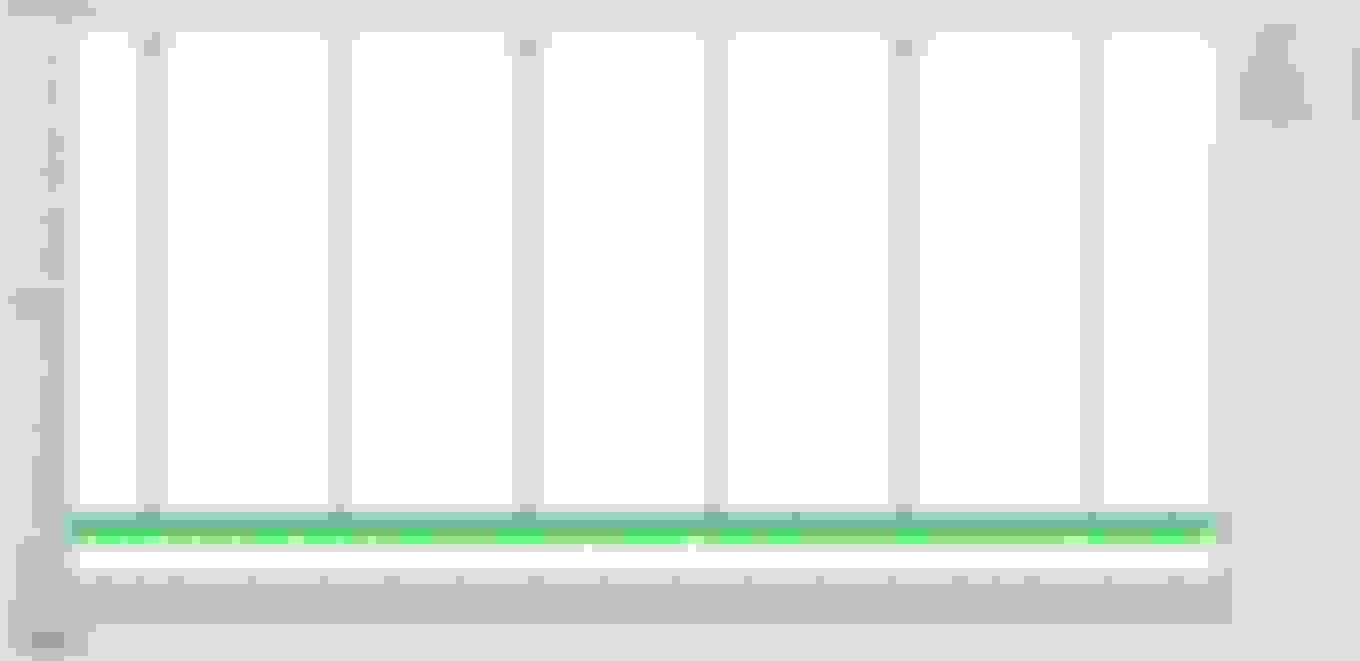
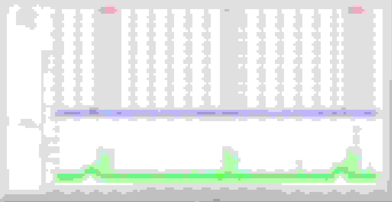
This shows the trailing select signal true over the secondary timing signal every other revolution. This is after i improved the current measurement (tho it is not scaled in amps) showing the injector pulse ( smaller magnitude) once every other rev. I had the injection timing set to TDC for this test to confirm that it was the injectors that caused the second low magnitude pulse. This shows the corrected injector pulses, smaller magnitude and once per rev. Also back to 95* BTDC timing. This shows the shape of the current draw of both leading and trailing coils with a 7ms dwell time. You can see that they saturate around 5ms. This was during cranking so everything was cold and the voltage was pulled down to around 10.8V while cranking.
Woo hoo first drive tonight!! I'm so excited. It ran surprisingly well with hardly any tuning. i took a ride around the neighborhood and decided it was running well enough to head across town to the pizza shop.
I worked out the trailing select signal and the latest tidbit i learned is that at higher RPMS, those coils start charging before the rising edge from the ecu. Im not sure how they know when to start, it must guess based on previous cycles. So its important to make sure the select signal is much longer than i had in the pics from before because if the select signal changes while its charging, it fires that coil and starts charging the other. Then i also learned that the ECU has a setting for mandatory off time, which was limiting me to about 2600 rpms, and then would spark every other firing event. That really confused the predictive nature of the coils, so there were some crazy long dwell events. So watch out for that.
i need to work on a bunch of fine tuning, but should be able to put some boost to it before long. Looks like it makes 1375mbar stock.
Anyway im rambling, but i am excited that it drives!!!
Played with stuff some more today, getting a fuel map filled in and starting to look at some of the more complex functions. i need some transient fueling, but i havent been able to figure out the motec wall film model yet so for now i've got none. it works well enough, just not snappy on a steep tip in. Then i need to work on the knock control, i need to make a knock tube so that i can actually tell when it is knocking. On the whole, its running pretty reasonably for only the second day of having it out in the wild.
 02-14-16, 10:47 AM