Wiring Gurus - Help Needed!
 08-26-16, 11:18 AM
#1
Wiring Gurus - Help Needed!
Hi guys - need some help from the wiring gurus.
In my quest to do crazy lighting things on my FD, I am in process of installing a sequential taillight modification. I am using a kit purchased from web electricproducts.com to convert the single blinking turn light system into one that uses all three lights so they fire in order, from the inner light out to the turn signal. Think Mustang and you have the idea.
To make this happen on the FD, I purchased two separate items, a TRC-1 Module that combine s separate brake and turn signal circuits into one system and STS-1 Modules that control the sequential firing of all three lights.
The problem is the instructions are pretty bad, the TRC-1 unit is no longer sold by web electric, and to compound matters, the company is on vacation for the next two weeks.
I installed the TRC-1 (one needed) and the STS-1 modules (two needed, with one attached to each taillight) and my problem is they currently do not fire in order (with the inner most light firing first and then the middle, followed by the outer light) but they act as one unit, meaning all three lights cycle together as opposed to sequentially.
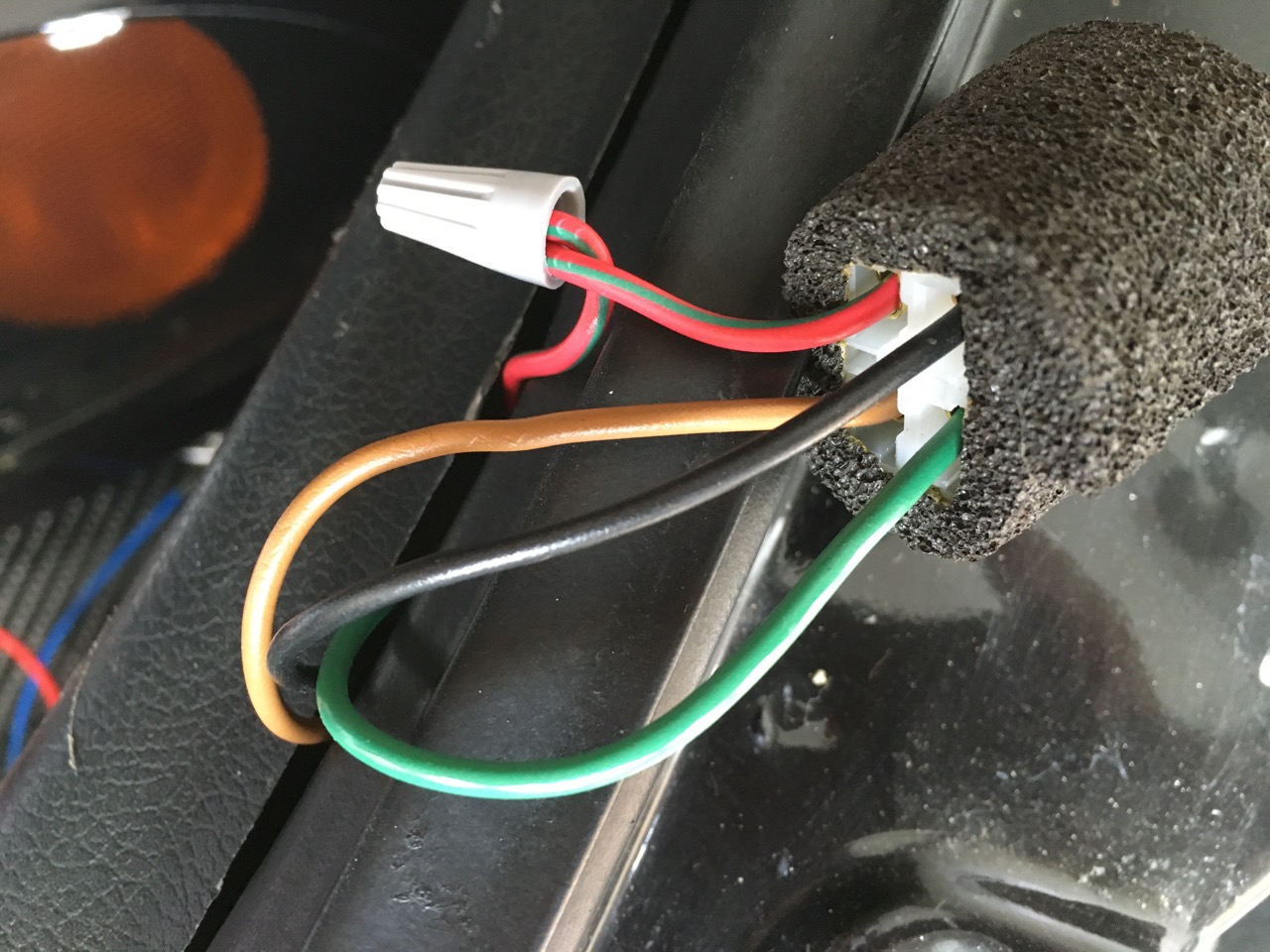
The FD has a three-bulb system, with the outside bulb being an 1156 socket with two wires and the inside two bulbs using 1157 sockets and three wires. I've attached some pics of the setup (ignore the twist connectors- these are for testing only and will be replaced with soldered heat shrink connections once everything works). The first pic is one of the harness plug, into which each taillight short harness connects. I used a voltmeter to determine the green wire is the brake wire, the red wire the parking light wire, the black is ground, and the red/green striped wire is for the turn signal.
HARNESS PLUG
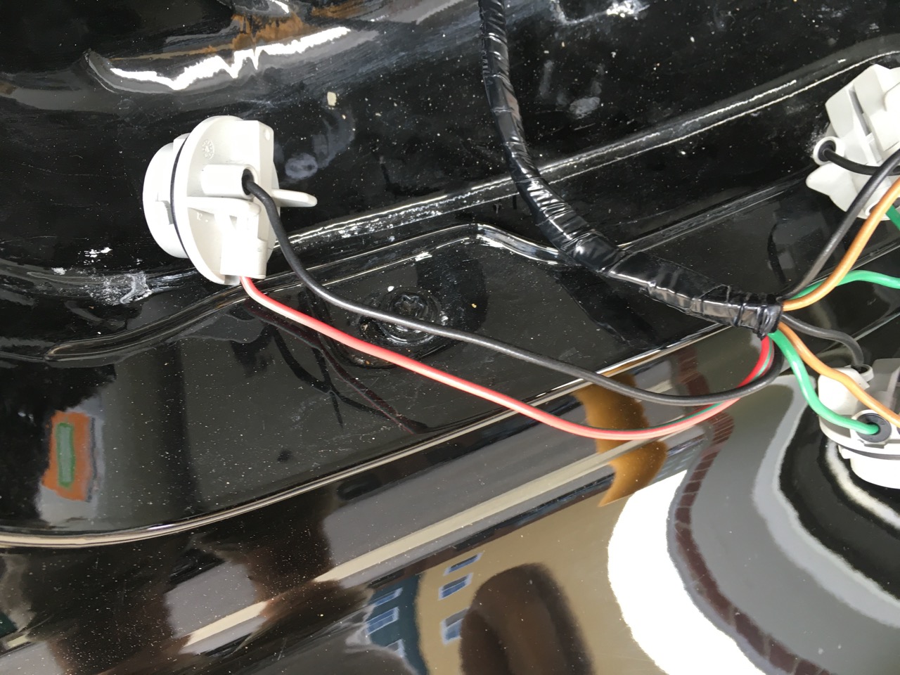
The second pic is the 1156 two-wire turn signal, or outer bulb socket. It has a black/ground and then the red/green turn signal wire.
TURN SIGNAL WIRES
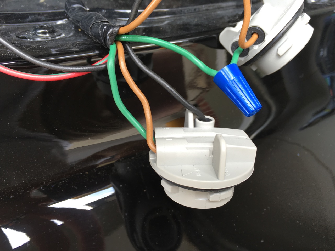
The third pic is of the 1157 sockets, and the FD has one inner and one middle socket. These have three wires, a black for ground, a red for the parking lights, and a green for the brake lights.
TWO BRAKE LIGHT WIRES
So, my question is, how to hook up the TRC-1 and the STS-1 units to get the lights to sequence on the turn signal?
I thought I had everything hooked up properly but testing fails. The parking lights work fine. When I activate the turn signals, all three lights blink at the same time but they do not sequence (meaning the inner light coming on, then the middle, then the outer). When I depress the brakes, the inner two lights come on, then the outer a second or so later and all three stay on.
As the directions (I have attached them) are not all that clear, it seems to me I have installed incorrectly the STS-1 modules as they are the ones that control the sequence operations. However, maybe the TRC-1 module is also wrong?
In particular, what confuses me are the following:
TRC-1 instructions -
1) Step one says to locate the brake wire. Okay, I did this by volt testing the wires. However, do you think they mean I need to tap into the brake wire before it goes out to each individual light harness or can I tap into the brake wire anywhere? I would not think it matters but maybe it does?
2) Step 6 says to connect the BROWN wire to the inside lamp MAJOR wire. I've never heard of major or minor wires before. I assume this (Major) means the wire that controls the brake light and the MINOR is the wire for the parking lights? Or does Major/Minor mean something else?
3) Step 6 also says "remember to connect the lamp MINOR wire to the tail light wire and the lamp GROUND wire to ground". What do you think this means? I've interpreted this to mean ensure the parking and ground wires for the lamp are connected normally (in other words, I didn't touch these two wires as the are wired already to the socket and to the harness).
STS-1 Instructions
1) The directions in step 2 say to locate for the inside bulb, the ground (which is black on the FD), the taillight wire (I assume they mean the wire for the brake light, which is green), and the turn signal wire (we don't have this on the FD inside two lights, just the outer light). So, I located one ground (black) going to the inner socket, one brake light (green) and did not have a turn signal wire as that is on the outside bulb only.
2) Step 3 says to expose the SIGNAL and GROUND wires at the harness. Do you think they mean I need to pull apart the harness BEFORE it splits off to the two tail light short harnesses? And by signal, I assume they mean the wire that activates the turn signals?
3) Step 7 says to attach the white STS-1 wire to the SIGNAL wire of the middle socket. By Signal wire, do they mean the wire that activates the brake light?
4) I did not hook up the CONTROL wire as it is listed as optional. Is this correct as I have seen some other installs that use the control wire connected to the red wire.
Thanks so much for the help!
In my quest to do crazy lighting things on my FD, I am in process of installing a sequential taillight modification. I am using a kit purchased from web electricproducts.com to convert the single blinking turn light system into one that uses all three lights so they fire in order, from the inner light out to the turn signal. Think Mustang and you have the idea.
To make this happen on the FD, I purchased two separate items, a TRC-1 Module that combine s separate brake and turn signal circuits into one system and STS-1 Modules that control the sequential firing of all three lights.
The problem is the instructions are pretty bad, the TRC-1 unit is no longer sold by web electric, and to compound matters, the company is on vacation for the next two weeks.
I installed the TRC-1 (one needed) and the STS-1 modules (two needed, with one attached to each taillight) and my problem is they currently do not fire in order (with the inner most light firing first and then the middle, followed by the outer light) but they act as one unit, meaning all three lights cycle together as opposed to sequentially.
The FD has a three-bulb system, with the outside bulb being an 1156 socket with two wires and the inside two bulbs using 1157 sockets and three wires. I've attached some pics of the setup (ignore the twist connectors- these are for testing only and will be replaced with soldered heat shrink connections once everything works). The first pic is one of the harness plug, into which each taillight short harness connects. I used a voltmeter to determine the green wire is the brake wire, the red wire the parking light wire, the black is ground, and the red/green striped wire is for the turn signal.
HARNESS PLUG
The second pic is the 1156 two-wire turn signal, or outer bulb socket. It has a black/ground and then the red/green turn signal wire.
TURN SIGNAL WIRES
The third pic is of the 1157 sockets, and the FD has one inner and one middle socket. These have three wires, a black for ground, a red for the parking lights, and a green for the brake lights.
TWO BRAKE LIGHT WIRES
So, my question is, how to hook up the TRC-1 and the STS-1 units to get the lights to sequence on the turn signal?
I thought I had everything hooked up properly but testing fails. The parking lights work fine. When I activate the turn signals, all three lights blink at the same time but they do not sequence (meaning the inner light coming on, then the middle, then the outer). When I depress the brakes, the inner two lights come on, then the outer a second or so later and all three stay on.
As the directions (I have attached them) are not all that clear, it seems to me I have installed incorrectly the STS-1 modules as they are the ones that control the sequence operations. However, maybe the TRC-1 module is also wrong?
In particular, what confuses me are the following:
TRC-1 instructions -
1) Step one says to locate the brake wire. Okay, I did this by volt testing the wires. However, do you think they mean I need to tap into the brake wire before it goes out to each individual light harness or can I tap into the brake wire anywhere? I would not think it matters but maybe it does?
2) Step 6 says to connect the BROWN wire to the inside lamp MAJOR wire. I've never heard of major or minor wires before. I assume this (Major) means the wire that controls the brake light and the MINOR is the wire for the parking lights? Or does Major/Minor mean something else?
3) Step 6 also says "remember to connect the lamp MINOR wire to the tail light wire and the lamp GROUND wire to ground". What do you think this means? I've interpreted this to mean ensure the parking and ground wires for the lamp are connected normally (in other words, I didn't touch these two wires as the are wired already to the socket and to the harness).
STS-1 Instructions
1) The directions in step 2 say to locate for the inside bulb, the ground (which is black on the FD), the taillight wire (I assume they mean the wire for the brake light, which is green), and the turn signal wire (we don't have this on the FD inside two lights, just the outer light). So, I located one ground (black) going to the inner socket, one brake light (green) and did not have a turn signal wire as that is on the outside bulb only.
2) Step 3 says to expose the SIGNAL and GROUND wires at the harness. Do you think they mean I need to pull apart the harness BEFORE it splits off to the two tail light short harnesses? And by signal, I assume they mean the wire that activates the turn signals?
3) Step 7 says to attach the white STS-1 wire to the SIGNAL wire of the middle socket. By Signal wire, do they mean the wire that activates the brake light?
4) I did not hook up the CONTROL wire as it is listed as optional. Is this correct as I have seen some other installs that use the control wire connected to the red wire.
Thanks so much for the help!
 08-26-16, 02:01 PM
#2
Super Moderator

iTrader: (1)
A casual glance at the instructions and your problem leads me to believe that the TRC-1 is in conflict with the STS-1 unit. I don't think you can use both units at the same time. In the STS-1 instructions, it says, "Be sure to note that your car might have three tail lights, but only 2 brake/turn signal lamps. If this is the case, you can modify your tail light fixture to have 3 brake/turn lamps by adding/changing a socket." Otherwise, the instructions would recommend using the TRC-1 unit as an alternate consideration to adding/changing sockets.
However, sitting down and drawing out the schematic diagram of how you want to set up your circuit is highly suggested. Take the diagrams from STS-1 and TRC-1 and combine it with the tail light schematic from the FSM. Labeling the inputs and outputs of the schematic will help out. Ues crayons or color pencils to help.
On a different note when using this sequential setup, you may confuse the driver behind you when he sees part of the red (brake) light on then followed by the yellow (turn) light. There was a reason why Mazda separated the turn light with yellow and brake light with red.
08-26-16, 02:14 PM
#3
Super Moderator
iTrader: (1)
I cannot guess what the manufacturer means by major and minor wire. It could mean gauge (thickness) of wire or the wire that triggers the light on/off? They would best answer that question.
08-26-16, 02:59 PM
#4
^ Thanks for the quick response. Yes, the major/minor thing has me thrown for a loop. Never heard the terms before. My best guess is that it means major = brake signal and minor = parking lights for the 1157 sockets and major = turn signal for the turn lights but I really am just shooting in the dark here.
I ordered the components about two years ago and am now finally getting around to installing them. When I ordered them, I sent the company a diagram of the FD setup. They are the ones that indicated both components (the TRC-1 and the STS-1) were needed with a three socket 1156/1157 combo setup. Might be wrong though.
I did sit down and draw out how to set these up based on what I comprehend from the directions but that hasn't worked. So, thought I'd throw this out to the forum for help.
You are also correct about possible confusion with using two red and one amber light for the setup. Once I get these operational, I am then going to tackle converting the amber turn signal to red as having all tail lights in red is legal/fine. It's just I'll need to do some heating up of red sense materials to bend it to the correct shape and I wanted to ensure it all works before doing that.
08-26-16, 03:40 PM
#5
Super Moderator
iTrader: (1)
David, you certainly are venturing into uncharted waters with this mod. I commend you for the endeavor! Perhaps you are correct in assuming the major wire is the bright (brake) light and the minor wire is the dim (parking) light.
As for combining both circuit boards, it sounds like one is in front of the other. It sounds like the STS-1 module needs to be the last circuit before the each bulb. Do you still have the schematic that you drew up? Since the company made some other modules to fit other vehicles then perhaps they could recommend a different setup or offer sound advice? That may not be too helpful since they are on vacation at the moment.
As for combining both circuit boards, it sounds like one is in front of the other. It sounds like the STS-1 module needs to be the last circuit before the each bulb. Do you still have the schematic that you drew up? Since the company made some other modules to fit other vehicles then perhaps they could recommend a different setup or offer sound advice? That may not be too helpful since they are on vacation at the moment.
08-27-16, 12:30 PM
#7
Super Moderator
iTrader: (1)
Proposed Sequential Turn Signal Schematic
David, I reviewed your schematic. It was busy! I also consulted my 94 wire schematics for the turn signals and brake lights. I noted a few errors and made the following changes. See the attachment.
Significant changes are:
1. Both STS-1 and TRC-1 circuits are wired between connectors E3-06, E3-07, and bulb sockets.
2. On STS-1 (both sides) connect the Black (Ground) wire to the Black (Ground) wires of each socket.
3. Place TRC-1 circuit in between E3-06 and E3-07 connectors.
4. On TRC-1, connect the Green (Ground) wire to the Black (Ground) wires of E3-06 and E3-07.
Best of Luck and let me know how it turns out!
Cheers,
George
Trending Topics
08-27-16, 12:49 PM
#9
Super Moderator
iTrader: (1)
A few more notes for you:
1. There is no need to mess with the Parking Light wires, they are R/B.
2. When the hazard switch is engaged, you may see both sides flash sequentially.
3. If you decide to use the control function of STS-1, then all 3 lights (either left or right) should flash simultaneously. Just remember to hook up both sides to the same switch.
08-27-16, 12:59 PM
#11
Super Moderator
iTrader: (1)
David, if all else fails you could go this route (just posted too): https://www.rx7club.com/vendor-class.../#post12100313
08-28-16, 01:36 PM
#13
Super Moderator
iTrader: (1)
Corrected Schematic
Here is a corrected schematic diagram for use. Specifically, the STS-1 Black wire must also be connected to Chassis Ground. The resolution of the schematic should also be higher as well.
I also want to remind all who may attempt this to ensure that electrical connection of this circuit combination is physically connected like this:
1. Bulb
2. Bulb socket
3. Socket wires to STS-1
4. STS-1 wires to TRC-1
5. TRC-1 wires to existing wire harness (E3-06 and E3-07, respectively)
6. The R/B wire for parking lamps remains untouched
7. All wires from the bulbs (minus parking wire) are severed from the existing harness and routed thru the STS-1 circuit.
Godspeed, David! I look forward to hearing about your results.
Last edited by Gen2n3; 08-28-16 at 01:45 PM. Reason: Added proper file attachment
08-31-16, 01:17 AM
#15
Super Moderator
iTrader: (1)
Sequential Turn Signal Schematic - Verified Good
David,
It was great news to hear that your sequential turn signals worked on Monday! Btw, are they still ok? Would love to see a video of it working!
I cleaned up the schematic as a reward for a job well done. I recommend keeping a hard copy of this schematic with other important car documents or in your FSM (if you keep a hard copy of that too).
Cheers,
George
08-31-16, 05:08 AM
#16
Thanks so much George. I just downloaded a copy of the schematic to my electronic Mazda FD folder for future reference.
Yes, the lights are working. I had some business to attend to yesterday so I didn't get out to the garage until later. Only had time to button up the taillight harness sides of the wiring. Soldered all connections and heat shrunk tubing over them so they are good to go. Cleaned up the wiring by removing the wires no longer used and by insetting into the weather proofing plug the new wires.
Still need to wrap up the above in electrical tape and then attend to the inside TRC-1 and STS-1 modules and their connections but that will need to wait until tomorrow. Once I get everything buttoned up, I will post some videos of how the lights work.
Thanks again for all the assistance. Could not have done this without your help.
08-31-16, 12:06 PM
#17
Super Moderator
iTrader: (1)
David, you are more than welcome! I am equally glad to hear that the lights continue to work without issue *knocking on wood*.
Now the hard part begins - clean up! That is a task I do not envy. Replacing wire nuts with proper splices, soldering, adjusting wire length, applying heat shrink, mounting the modules, closing up panels, etc... isn't glamorous but necessary. Remember to slip on the heat shrink tube BEFORE crimping/soldering the wire connections! That can be very frustrating, ask me how! Here is another tip when wire splicing: space out splice points in a wire bundle to avoid bulging in one spot. This keeps the wire bundle streamlined and avoids a common break point in the bundle that prevents multiple wires from shorting out. Finally, consider using lacing cord (aka spot tie) instead of using zip ties to manage wire bundles. You would avoid seeing the bumps from the zip tie locking mechanism, prevent wire chafing from locking mechanism, and is less likely to bind when removing/installing from confined spaces.
Take your time putting everything back together. I am excited to see the fruits of your labor.
Cheers,
George
Now the hard part begins - clean up! That is a task I do not envy. Replacing wire nuts with proper splices, soldering, adjusting wire length, applying heat shrink, mounting the modules, closing up panels, etc... isn't glamorous but necessary. Remember to slip on the heat shrink tube BEFORE crimping/soldering the wire connections! That can be very frustrating,
ask me how! Here is another tip when wire splicing: space out splice points in a wire bundle to avoid bulging in one spot. This keeps the wire bundle streamlined and avoids a common break point in the bundle that prevents multiple wires from shorting out. Finally, consider using lacing cord (aka spot tie) instead of using zip ties to manage wire bundles. You would avoid seeing the bumps from the zip tie locking mechanism, prevent wire chafing from locking mechanism, and is less likely to bind when removing/installing from confined spaces.Take your time putting everything back together. I am excited to see the fruits of your labor.
Cheers,
George
08-31-16, 02:14 PM
#18
Too funny you mentioned putting on the heat shrink before soldering - didn't do that a few times yesterday. 
I've pretty much followed what you state about spacing out the joints etc. With the soldered joints that I heat shrunk on the actual taillight harnesses, I am now going back with electrical tape to wrap up the bundles like the OEM ones were done. There are a few more wires now in each bundle.
As for what is inside the trunk, my plan was almost the same as above. To solder everything, heat shrink tubing over the joints and then to zip tie the wires together (one difference). I am then going to wrap with wiring loom and planned on using electrical tape to wrap it all up, like the OEM wiring bundles are done. Should turn out well.
As for the lacing cord, never tried that before but it looks like a really good idea. I'd try it if I had some around but my inner clock says to knock this out while I am still enthused about the project.
08-31-16, 10:29 PM
#19
Super Moderator
iTrader: (1)
Optional Control Switch - Proposed
David, don't feel pressured into trying this. If you like, experiment with this in the future when the instrument cluster is removed.
This is a follow-up schematic for the Control Wire segment of the STS-1 circuit. This is a PROPOSED schematic so proceed with care.
The recommended switch to use is a double-pole double-throw rocker switch.
Best of luck to all who try this schematic!
George
This is a follow-up schematic for the Control Wire segment of the STS-1 circuit. This is a PROPOSED schematic so proceed with care.
The recommended switch to use is a double-pole double-throw rocker switch.
Best of luck to all who try this schematic!
George
Last edited by Gen2n3; 09-01-16 at 10:23 AM. Reason: Added DPDT Switch Drawing
09-01-16, 09:28 AM
#20
^ George, you are going above and beyond. Thanks so much. Had a few minutes this morning to work on buttoning up the wiring. The taillight harness wiring is done and wrapped in electrical tape like the OEM ones. I placed the left STS-1 and TRC-1 modules next to the ABS ECU unit on the left side of the car - zipped tied them in upright positions to keep water out. Got all the left side inside wiring soldered and heat shrunk and the wires running to the right side from the TRC-1 done as well. Now need to affix the right side STS-1 module and solder up its connections as well as button up the wring and I will be done but need to run out for meetings. Maybe later tonight.
09-01-16, 10:30 AM
#21
Super Moderator
iTrader: (1)
David,
Nice work on cleaning everything up! Are you taking some photos along the way to record the clean-up process? I could only imagine how clean the wire re-wrapping goes! On a separate note, I added a generic DPDT switch sketch on the new schematic in case anyone has difficulties wiring one up.
Cheers,
George
09-03-16, 01:25 PM
#22
So, an update and a few pics as well as a video. I finished up the wiring and putting everything back together.
For the wiring, I soldered and heat shrunk each joint and then bundled the wires together with electrical tape. I then used flex tube to cover the bundles and used electrical tape to cover the flex tube. For small bundles (like the taillight harnesses) I used 3/8 inch flex tube and for larger bundles, 3/4. So, I ended up with wiring that comes close to matching OEM.
For the ignition portion of the wiring, I used the Haltech relay box to tap into a spare ignition on slot. I used wire loom to run the ignition wire into the box so it too looks OEM.
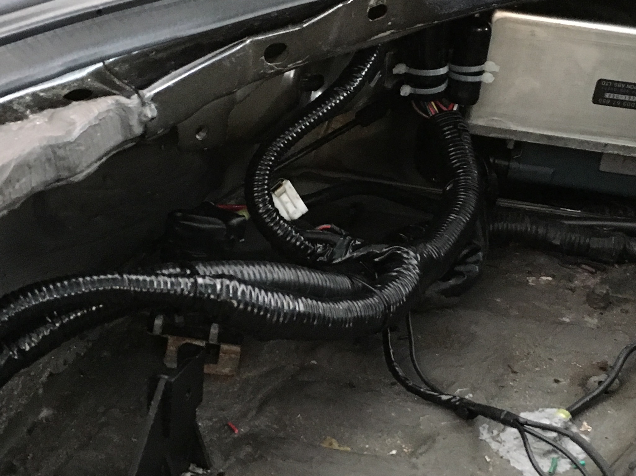
Here is a pic of the wiring on the driver's side. I ticked one STS-1 module and the TRC-1 next to the ABS ECU and zip tied them in an upright position so no water can enter:
Here is a pic of the wiring for the left side. I drilled two holes into the center metal bracket and zip tied the other STS-1 module there:
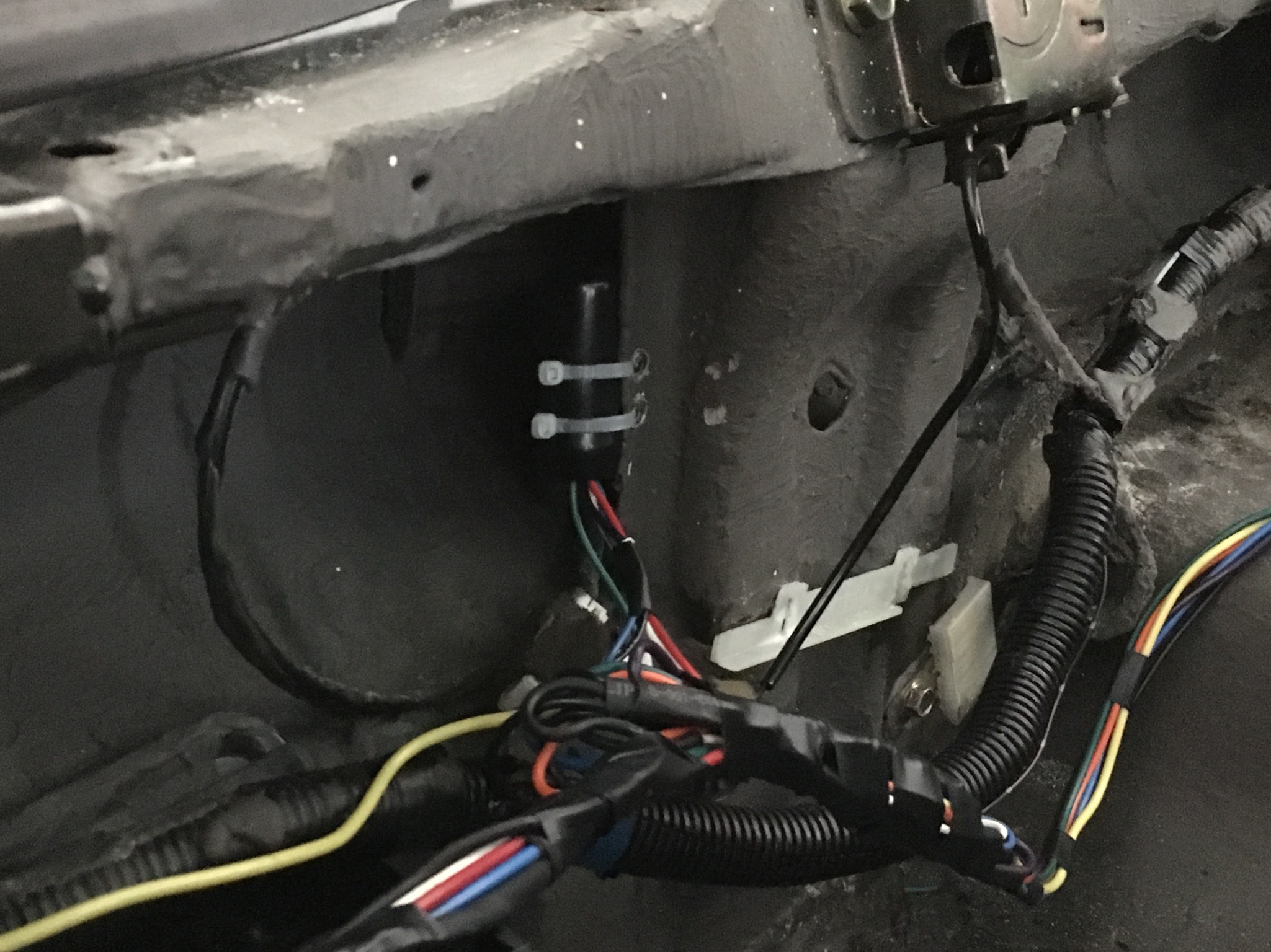
Note, if you are wondering about the grey material on the inside of the trunk, it's a sound dampening material that I sprayed on a number of years ago. Worked great BTW.
So in the video - I don't know how to embed the video in this post so click on the file to open it - you will see how the turn signals now operate. As a disclaimer, my taillights are highly modified by me with a three circle parking LED parking light design and then, with crazy bright LEDs mounted to circuits for the brakes and the turn signal. So, if you try this, your units won't like quite the same but will function sequentially like mine do.
I'd take more videos to show what the lights look like when you hit the brakes and use the hazard. but I need someone else to assist and my wife is not here. So, for now, a description. When you hit the brakes the lights on both sides sequence once from the inside to out and then stay on. The center light works as normal (but mine is all LED with a diffused lens). For the hazards, the lights on both sides continue to sequentially flash from the inside to the outside.
Finally, it's not the taillights, but her is a pic of the LED conversion I did to the turn signals. I modified the inside of the 99 spec turn units to use two LED halo rings and a DRL light on the outside (I converted the 1156 socket to an 1157) with a switchback bulb. So, when the ignition comes on, the lights look like thisL
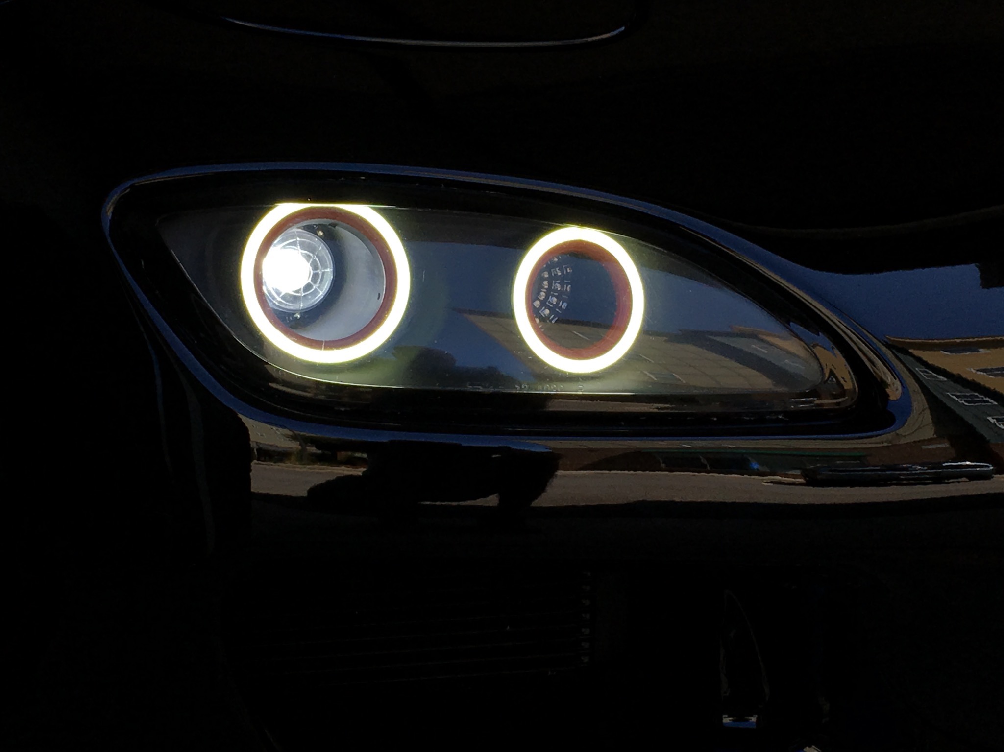
When you activate the turn signal, the LED halos and white DRL go out (while the other side remains lighted) and the outside white DRL flashes amber. Once completed with the turn, the units return to the normal LED halos and white DRL.
It's now back to the garage to tackle the mystery ground problem with the Pioneer head unit!
For the wiring, I soldered and heat shrunk each joint and then bundled the wires together with electrical tape. I then used flex tube to cover the bundles and used electrical tape to cover the flex tube. For small bundles (like the taillight harnesses) I used 3/8 inch flex tube and for larger bundles, 3/4. So, I ended up with wiring that comes close to matching OEM.
For the ignition portion of the wiring, I used the Haltech relay box to tap into a spare ignition on slot. I used wire loom to run the ignition wire into the box so it too looks OEM.
Here is a pic of the wiring on the driver's side. I ticked one STS-1 module and the TRC-1 next to the ABS ECU and zip tied them in an upright position so no water can enter:
Here is a pic of the wiring for the left side. I drilled two holes into the center metal bracket and zip tied the other STS-1 module there:
Note, if you are wondering about the grey material on the inside of the trunk, it's a sound dampening material that I sprayed on a number of years ago. Worked great BTW.
So in the video - I don't know how to embed the video in this post so click on the file to open it - you will see how the turn signals now operate. As a disclaimer, my taillights are highly modified by me with a three circle parking LED parking light design and then, with crazy bright LEDs mounted to circuits for the brakes and the turn signal. So, if you try this, your units won't like quite the same but will function sequentially like mine do.
I'd take more videos to show what the lights look like when you hit the brakes and use the hazard. but I need someone else to assist and my wife is not here.
So, for now, a description. When you hit the brakes the lights on both sides sequence once from the inside to out and then stay on. The center light works as normal (but mine is all LED with a diffused lens). For the hazards, the lights on both sides continue to sequentially flash from the inside to the outside.Finally, it's not the taillights, but her is a pic of the LED conversion I did to the turn signals. I modified the inside of the 99 spec turn units to use two LED halo rings and a DRL light on the outside (I converted the 1156 socket to an 1157) with a switchback bulb. So, when the ignition comes on, the lights look like thisL
When you activate the turn signal, the LED halos and white DRL go out (while the other side remains lighted) and the outside white DRL flashes amber. Once completed with the turn, the units return to the normal LED halos and white DRL.
It's now back to the garage to tackle the mystery ground problem with the Pioneer head unit!
Last edited by David Hayes; 09-03-16 at 01:29 PM.
09-03-16, 01:40 PM
#23
Super Moderator
iTrader: (1)
Exceptional work, David! You put a lot of time and heart into rebuilding the wire harnesses and it shows. Thanks for including a short video clip of the sequencing tail lights. Perhaps sometime soon we could see how it all functions with the brake (1 pulse then all on), hazards, brake w/ turn lights?
Again, terrific work! Looks like it's Miller time!!
Cheers,
George
Again, terrific work! Looks like it's Miller time!!
Cheers,
George
09-03-16, 04:31 PM
#24
Thanks George. Fixed the ground issue with the stereo. The stereo guy had mistakenly hooked up the ground for the subwoofer with the ground for the head unit. At least on a Pioneer unit, you have to isolate the ground. Solved the feedback issue.
Down to two electrical gremlins. 1) The seatbelt warning light stays illuminated and 2) strangely, when you depress the brake pedal, the fuel pump primes (pressure goes up from 20 PSI to 40) and this is with the ignition off.
Going to tackle those tomorrow. As for Miller time, yes!! War Eagle, go Auburn!!