When you click on links to various merchants on this site and make a purchase, this can result in this site earning a commission. Affiliate programs and affiliations include, but are not limited to, the eBay Partner Network.
Good to hear that your tach is spot on with the ECU.
The only suggestion that I could offer would be to remove the solder on all of IC1's joints on the tach. If you plan on doing this yourself, remove all the solder from each joint minus 2. This will keep the IC in place. Once the solder from the other joints are replaced, replace the old solder from those 2 joints. You MUST remove all solder from the eyelets without causing damage to the eyelets and pins from the IC. Again, IC1 cannot be easily replaced! It is out of production and MUST be sourced from another FD or another vehicle that used the same IC chip.
Please remind me of the soldering tools you have to do this procedure?
BTW, where in CA are you?
Cheers,
George
Guess the tach needs to come out once again. I'll try my best not to damage the eyelets but I don't think this will be much of a problem since I won't actually be removing the IC chip. At least I hope so.
(2) Soldering irons, both without variable temp control
soldering wick
solder vacuum pump
(3) different flux
lead free solder with rosin core 0.6mm and 2 other solder wire which I won't be using
quadhands deluxe helping hands
Copy, all. The 90W iron will cook your eyelets quickly; I wouldn't recommend using it unless absolutely necessary. The 30W iron may suffice but you may have to apply heat longer to the eyelet for solder to flow properly through the joint. The de-solder braid (wick) will probably be easier to remove solder on the eyelets. Adding flux to the wick will also ensure solder flows from the old joint into the wick. Remember to add flux first, then apply heat to the joint, and finally feed the solder to the iron's tip. The flow should take approx 1sec.
Take some pics along the way and post your progress. Best of luck on your repairs!
Cheers,
George
The 30w iron ended up not working so I had to use the 90w iron. I did exactly as you described. I did mangle up a few of the eyelets but I think I pretty much got most of it done. Before I begin resoldering the pins I wanted your input. Here are pictures of the work.
Please repair the eyelets before resoldering the IC. That 90W iron caused quite a bit of damage. Do not use it any longer for circuit board repair. I seriously recommend that you look for a PCB (Printed Circuit Board) repair company who could work some magic on those eyelets. It may cost you some $$$ but you DON'T want to mess this up!
The board is typically rendered useless once an eyelet is severed from its trace. Also consider the high heat could damage the IC. There are microscopic wires that run inside the chip. When excessive heat is applied to 1 or more pins, it may cause these micro wires to vaporize. You already gambled on the lifted eyelets for the capacitors but do not gamble on the IC eyelets. The electrical bond to an IC chip is CRITICAL! It would potentially cause ghost problems and the tach would never function properly again.
This type of repair requires the skills of an experienced technician. Please don't confuse enthusiasm for competency when soldering electronic components. Again, this is no easy repair and you could scrap your board! Recognize your boundaries and seek help from an expert.
For your review, consider this company...I just googled it: AER Technologies
They are located here:
AER Technologies, Inc.
650 Columbia Street
Brea, CA 92821
IMHO, when I damage an eyelet (it's rare), I seek help from an expert!
I just noticed this unusual shape on this solder joint. What is it connected to? Was that to either C1 or C5? Can you get a different angle on it?
Cheers,
George
I guess I got lucky, George. I went ahead and soldered the pins and tested it. Everything turned out fine. The 3k flickering is officially gone. I can hold the tach at 3k without any issues. Resoldering the IC solved the issue. The car is cold so I can't rev past 4k but once I get a chance and the car warms up I'll check the entire bandwidth.
That picture you noted with the bad solder joint was part of the the previous damaged eyelet we discussed earlier. Fortunately it traced through with minimal resistance.
As you know I am very much a novice when it comes to PCB soldering as apparent by my work. However I can't help myself when it comes to new experiences even at the expense of damaging what I'm working on. Personally, the knowledge and experience I gain significantly outweighs the expense. At least most of the time when the costs are not overwhelmingly high. I think I leveled up a bit going from completely damaging eyelets, to mangling them, to causing no damage at all.
As always I'll get a video up when I can.
The force may have been with me on this one, George.
You should buy a lotto ticket with that kind of luck! Congratulations on fixing your tach and the eyelets. Please post that video when the car warms up. Do you have any photos of the board after you soldered the IC back into place? How did you straighten out those eyelets?
You should buy a lotto ticket with that kind of luck! Congratulations on fixing your tach and the eyelets. Please post that video when the car warms up. Do you have any photos of the board after you soldered the IC back into place? How did you straighten out those eyelets?
Cheers,
George
I've been buying tickets but my luck doesn't seem to apply.
I thought I took pictures after i soldered it back on but I guess I didn't because I can't find them on my phone.
I tried to make an initial attempt to straighten out the outlets by pushing the IC pins against the wall as well as pushing/pulling using a fine hook needle. It didn't really do too much, in hindsight I probably should have heated it a bit to soften the eyelet for easier manipulation.
The video is going to be a bit. When I setup the laptop with wari for the adaptronic ecu to determine if the RPM matches I noticed the wideband reading 19.5:1. Coupled this with a hissing sound coming near the turbos I figured I have an exhaust leak. As of now the car is down until I can locate and repair the exhaust leak.
In process of completing multiple tasks but had an opportunity to warm up the car enough to make this quick video of the tach going up to approximately 6k. Charge pipes and intake setup completely removed with obvious vacuum leaks hence the high idle. Video linked below.
Well done! I'm very happy to see your repairs were successful. Best of luck tackling those vacuum leaks.
Cheers,
George
All thanks to you!
The vacuum leaks should be fixed once I put everything back together again. I had to find an exhaust leak and figure out what was going on with the innovate wideband, fix the compatibility issue with the aftermarket alarm system, redo some wiring on the car that didn't meet my expectations, and a bunch of other stuff I continue to discover with this site unseen purchase. Still worth every penny. Just want to be able to drive it with confidence.
This is an update to the Speedometer Board Connector that AlienR2 (Jeff) made in Post #8 of this thread. His original post can be found here: Post 8. This update comes as a result of studying the Flex Print on the back side of the Instrument Cluster. I sketched a schematic that represents an electrical and physical location of key components on the flex print. One of the big breakthroughs was adding clarity to the Speedometer Connector Input/Output Pins. That thread can be found here: Instrument Cluster Flex Print Components.
This post contains photos of the Speedo Connector with a legend of its pins. Thanks in advance for reading this post and/or commenting on potential discrepancies.
I also wish to extend a special thanks to DaleClark for providing the specimen circuit boards to study in further detail. This particular Speedo board comes from a USDM 1993 Instrument Cluster with Manual Transmission. Thank you, Dale!
Cheers,
George
NOTE: Refer to an updated photo of the top side of the Speedo Board with Pin legend. See Post 158
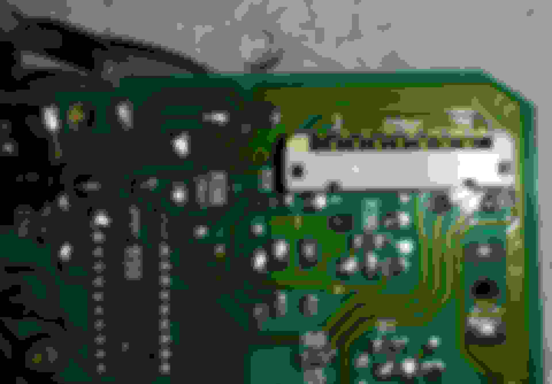
Back side of Speedo Board with Connector Pins labeled. Note the stencils of 1, 2, 14, and 15 above and below the connector. The flash drowned out 15.
Last edited by Gen2n3; 06-01-19 at 12:56 AM.
Reason: Added note about Post 158
This Speedo board was graciously donated for science. A special thanks to David Hayes for this donation! The majority of its components were removed from the top side. All that remains are the ICs and LCD Display. More to follow from this teaser!
Cheers,
George
Coming Soon to a Speedo Troubleshooting thread near you!
This excerpt was copied from my Body CPU Components List thread. It describes a method to neutralize any leaked electrolyte from any capacitors, especially from C3.
Spot clean affected areas with distilled water and baking soda. Use a tooth brush, cotton swab, and/or acid brush to clean the localized areas with baking soda and water solution. This would be the same as cleaning your car battery so expect to see some foaming action. That is the baking soda reacting to the acid. Do NOT soak the board or let the water stand. Let it drain off the board. Dry the affected areas with a hair dryer. Slowly move it (hair dryer) around to avoid hot/burn spots. Once dried, use isopropyl alcohol to clean up the solder joints. Inspect each joint for any damage. The component may not need to be replaced but the solder may need replacement. This will ensure a positive physical bond and a clean electrical bond.
Can you shed some light on why i might be seeing 5v on my 12v tach pin? I've checked the blue/red cable on connnector c01-01-4e and i have 12.58v there but only seeing about 4.9v at the tach connector screw. When i turn the ignition on the redline buzzer sounds (the ecu makes the tach do a sweep) but the needle doesnt move; I'm guessing its to do with this voltage issue that i have?
Can you shed some light on why i might be seeing 5v on my 12v tach pin? I've checked the blue/red cable on connnector c01-01-4e and i have 12.58v there but only seeing about 4.9v at the tach connector screw. When i turn the ignition on the redline buzzer sounds (the ecu makes the tach do a sweep) but the needle doesnt move; I'm guessing its to do with this voltage issue that i have?
any help is appreciated,
Brad.
as a quick trial i jumped IGN 12v from the unused empty screw over to the 12v bolt that holds the tacho in and hey presto it worked, unsure if there is any negative effects from this however it is easy to do with the cluster out and doesnt require trying to put a ring terminal on the back of the cluster while in the car to bridge to the battery cable in the original connector. I borrowed George's diagram to illustrat what i did below:
as a quick trial i jumped IGN 12v from the unused empty screw over to the 12v bolt that holds the tacho in and hey presto it worked, unsure if there is any negative effects from this however it is easy to do with the cluster out and doesnt require trying to put a ring terminal on the back of the cluster while in the car to bridge to the battery cable in the original connector. I borrowed George's diagram to illustrat what i did below:
temporary fix for tacho not working.
Brad,
Sorry for the delayed reply. I am glad to see that the flex print schematic helped your problem. This jumper you installed is a temp fix; please do not make it a permanent fix. You must also be very cautious to isolate the wire between the 2 screws to avoid short circuits. If you saw +12V at Connector C1-01 Pin 4E and low voltage at the Tach Pin then that indicates a problem with the Speedo Board and/or the flex print.
As you were diagnosing this problem, did you remove the Speedo board and inspect it? Did you see anything unusual? Remember, the Tach gets its signals from the Speedo board. Did you visually inspect the flex print for any breaks in the run between the Speedo connector (Con1) and the 3 screws? The bend at the Speedo connector would be the weakest point. You could also have some damaged/leaked capacitors on the Speedo board that may require replacement.
What ECU do you use that causes the Tach to "wake up" and sound the over-rev buzzer?
gonna be tackling the tacometer re-solder process here shortly as I have the jumping issue. i've already taken it apart before and replaced the capacitors on the odometer/speedo board which solved my odometer issue.
which connections specifically should I be re-soldering? seems like the main processor(IC) is usually the issue? and which capacitors should I replace to be safe? also what temp should I be using on my iron? I have a pretty badass weber one at work that is variable up to 700 Deg I believe.
also, it seems that its very important to put the tach needle back on in the same exact location it was taken off? any tricks to this?
For tachometer repair, follow this link: Tach going Crazy Post#2 It has a PDF file that guides you. Basically, replacing the solder on the IC should fix the bouncing tach issue. Capacitor C1 is an electrolytic capacitor, if you are inclined to replace a cap then that is it! Sonicgroove made a successful repair to his Tach, so he would be better qualified to answer specific questions on other tips. Re-read our conversation in this thread to gain more insight on his repair. I cannot specify a temp range to use on a solder iron because I use a basic 40W iron.
General advice I can offer: Use flux when soldering. Be careful not to lift any eyelets on the board! You don't want to overheat the IC with repetitive heat cycles. An IC should technically be heated twice - first to install on a PCB then second to remove it from a PCB. The reason: repeated heat cycles will damage the hairline wires inside the dye.
Cheers,
George
Ok, ill probably start at around 300 deg and go up until I can get the solder to melt. I did read that PDF and its a little confusing on the removal/reassembly process of the tach needle. maybe Sonicgroove can chime in?
Afternoon all! I am looking into the repair of this speedometer board for a fellow member and would like to share some photos/observations. First, the discrepancies!
1. Odo screen blank.
2. Speedometer and tachometer needles were bouncing but suddenly died.
Upon closer examination, I observed several problems. First, the obvious smoke/fire damage to ZD4. I would bet dimes to donuts this was the culprit of the sudden death of tach & speed needles. Second, physical condition of the capacitors looked normal, no abnormal swelling. Third, I observed some corrosive effects of leaked electrolyte on the following components: DA1, TR7, DA2, C3, C4, C6, C1, R18 (along with some charring), R25, ZD8 (along with some charring), and ZD9. I believe repairing C3 and associated capacitors would restore the odometer.
Parts that are scheduled for replacement are C1, C3, C4, C6, and ZD4. I am very concerned about damaging one eyelet to ZD4 because the area surrounding it appears to be heavily charred. Oddly, the diode itself does not look to be damaged. The smoke only looks like it came from the board surrounding the eyelet! The backside of the circuit board looks normal - no charring or damage is apparent.
No components were removed. However, the speedo board was prepared. First, any smoke was cleared from the board with isopropyl alcohol. Then a mixture of water and baking soda was applied around the components affected by electrolyte with an acid brush. There was a fresh water rinse and then another brush of the affected components with isopropyl alcohol. Note, the water-baking soda mixture and fresh water was sparingly brushed on and the circuit board was held upside down to prevent any water from going underneath any IC chips. A heat gun on the lowest setting was also used to evaporate any standing water on the circuit board before the alcohol was applied. Again, these steps were used to help neutralize any remaining electrolytes on the board.
Here are the photos. Please read the captions under each photo for additional information.
Cheers,
George
Damage to eyelets of C1 and R25. C1 slated for replacement.
Damage to eyelets of C4 and C3. Both capacitors will be replaced. Should restore the odometer.
Damage to eyelets of TR7 and DA1 (not shown). Only solder will be replaced.
Top down view of Zener Diodes ZD4, ZD7, and ZD5. ZD5 & ZD7 have eyelet damage from electrolytes. Note the heavy charring on ZD4. Corrosion to DA1 and TR7 eyelets visible at bottom-center.
Close-up of ZD4, ZD5, & ZD7. Note the charring around one eyelet of ZD4. ZD4 will be replaced. Extreme care not to damage the eyelet must be taken.
So here is an update on the repairs to the above Speedo Board in Post #124. The damage to Zener Diode, ZD4 was not actually on the diode.
Each photo has a brief note so you know what to look at. I used a 16x Jeweler's Loupe and an x-acto knife to excavate the charred remains of the board. It left a nice hole. The good news about this damage was it did not penetrate to the backside of the board. So that meant there was enough material to provide some stability for repair. Much like a pot hole in the street, I used a filler...an epoxy putty to fill in the hole. This was a tricky task because of the fast set time and the small space to work around. None the less, the epoxy set and is solid.
Excavated hole patched with epoxy putty.
The next photo shows the area after the Zener diode was removed. I inspected both eyelets to ensure no problems would arise from soldering in the new component. The repair to the eyelet area was made first because heat from the solder iron may have caused damaged to it.
ZD4 removed and clearly shows repaired eyelet area.
The remainder of the photos show the replaced components, with 2 exceptions. Capacitors C2 and C4 are not installed. Each location has one fouled eyelet. To avoid heat damage from the soldering iron, I used a Jeweler's drill & bit to bore open each eyelet. The solder quickly gave way and no damage to the eyelet occurred. Mission accomplished!
Green boxes/circles show new components installed. Red circle shows 1 plugged eyelet.
Different angle: Green boxes/circles show new components installed. Red circle shows 1 plugged eyelet.
This photo shows the last 2 capacitors, C2 and C4 replaced. The board now must be tested.
Green Circles show new capacitors installed onto board.
It is important to note that ZD4 was replaced using a suitable replacement from the FD Speedometer-Odometer Circuit Board - Components Only thread. The old component was tested on the board and had the same measurements to a similar board. However, it was replaced to reduce any chance of additional failures.
 03-23-18, 10:53 PM