Speedhut Gauge Install: How to (DIY)
 12-18-17, 12:42 PM
#1
Speedhut Gauge Install: How to (DIY)
I have done a full conversion to speedhut gauges, and thought I would share my process. I was able to retain all the factory housings and bezels for a complete stealth look. I did all of this in about 3 hours, and no major fabrication was necessary for an OE look. First of all, you will need to order these sizes:
4.5" Tachometer
4" Speedometer
2-1/16" Oil pressure
2-1/16" Water temp
2-1/16" Fuel gauge
I have seen a lot of people order the smaller 4inch tach, or get the 3-3/8 speedo. Dont do this. I actually measured the holes, and the 4.5" tach and 4" speedo work perfect. They actually measure out almost identical to the diameter of factory gauges. Trust me.
So for those of you that dont know, the speedhut gauges include their own bezel (usually aluminum) and their own rings to mount them. They also have a button (if programmable) and their own plexi-glass window. We will be ditching the plexi-glass window and aluminum bezel in order to make the factory mazda pieces work.
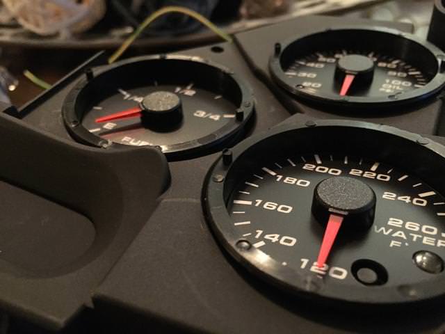
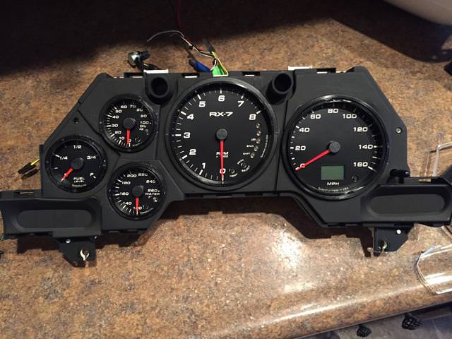
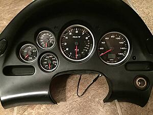
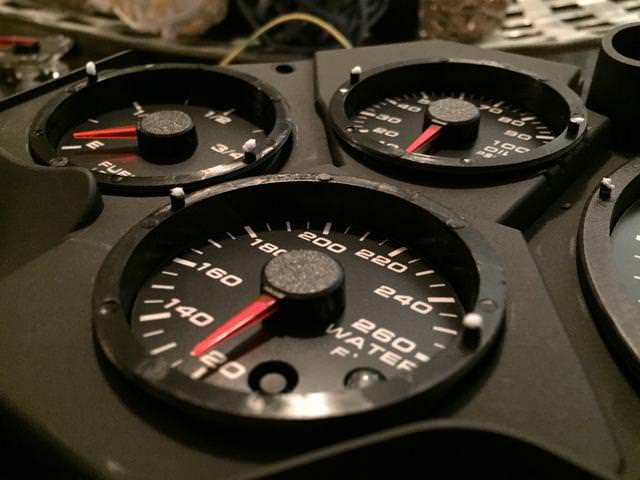
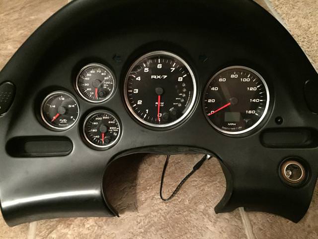
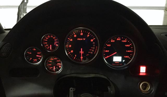
So here is how the speedhut gauges look compared to the stock ones:
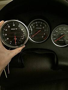
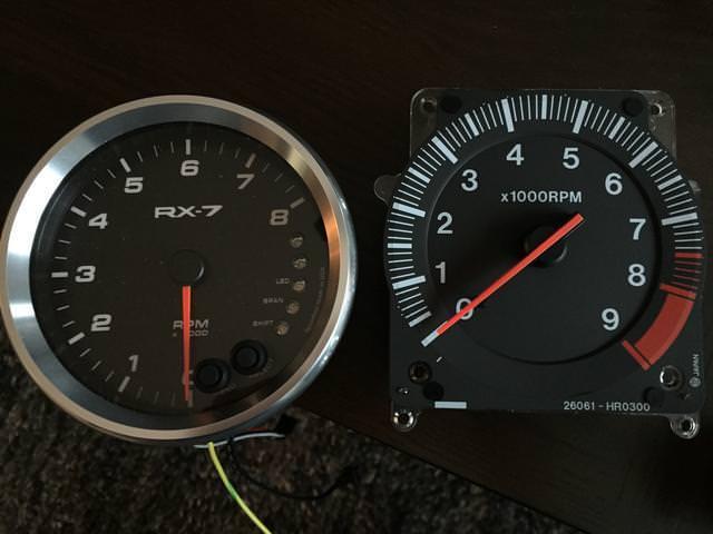
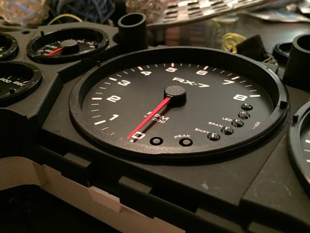
I went with the Revolution style gauge with white font. I also had the custom lettering put on to say "RX-7" ($10 option)
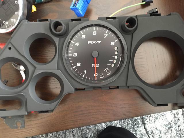
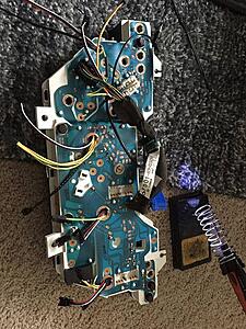
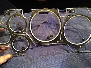
First step is to remove the cluster obviously and unclip the clear lens cover and the black plastic backing from the cluster assembly.
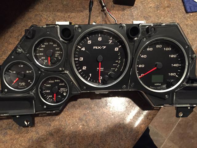
You will be left with this:
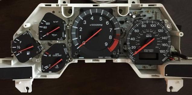
The stock gauges themselves unbolt from the back. There are about 3 bolts per each of the gauges. Go ahead and remove them so that you have an empty piece of white plastic (don't mess with the circuit board paper on back, we need to retain this for the turn signals) but you can go ahead and start removing the larger bulbs that screw in from the back.
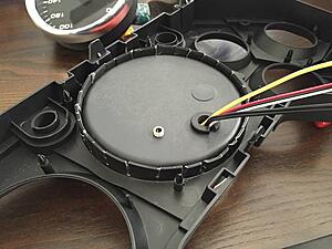
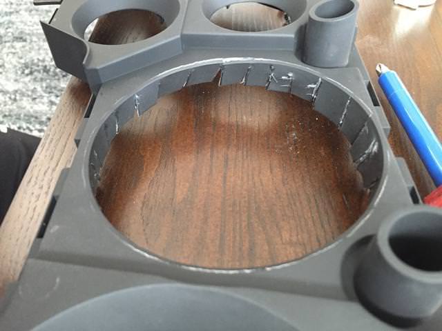
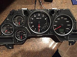
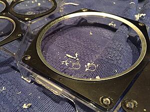
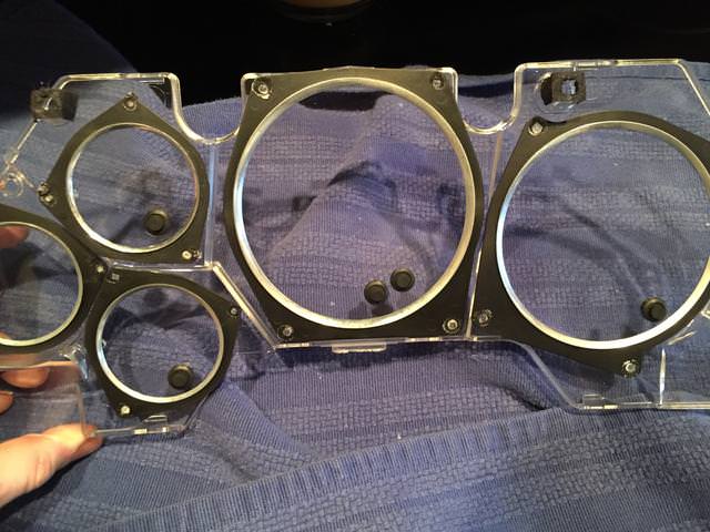
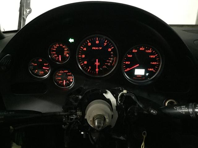
Now looking at the black plastic gauge housing, you will notice that these holes are way to small for our large gauges. I used some side cuts and started making cuts into the edges of the housing. This effectively opens up the holes for the larger gauges. Then I literally threaded the gauge body into the housing. bottom them out until they sit flush at the front.
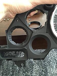

Dont worry about being neat, this cant be seen. Gauge will "press/thread" in:
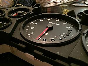
Tach installed: notice the alumium bezel is removed and the slider ring on the back is also ditched.


4.5" Tachometer
4" Speedometer
2-1/16" Oil pressure
2-1/16" Water temp
2-1/16" Fuel gauge
I have seen a lot of people order the smaller 4inch tach, or get the 3-3/8 speedo. Dont do this. I actually measured the holes, and the 4.5" tach and 4" speedo work perfect. They actually measure out almost identical to the diameter of factory gauges. Trust me.
So for those of you that dont know, the speedhut gauges include their own bezel (usually aluminum) and their own rings to mount them. They also have a button (if programmable) and their own plexi-glass window. We will be ditching the plexi-glass window and aluminum bezel in order to make the factory mazda pieces work.
So here is how the speedhut gauges look compared to the stock ones:
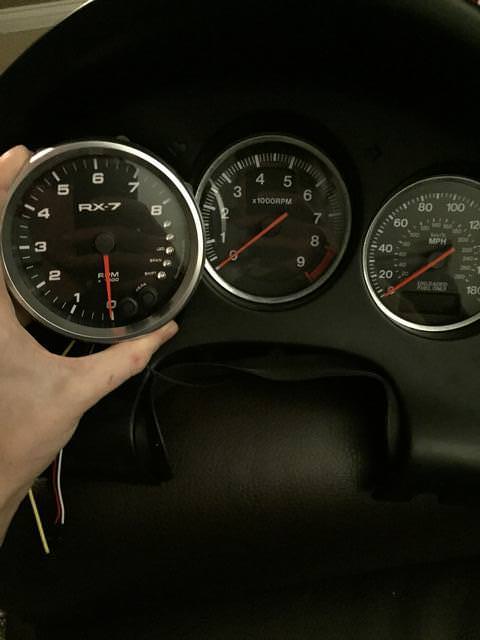
I went with the Revolution style gauge with white font. I also had the custom lettering put on to say "RX-7" ($10 option)
First step is to remove the cluster obviously and unclip the clear lens cover and the black plastic backing from the cluster assembly.
You will be left with this:
The stock gauges themselves unbolt from the back. There are about 3 bolts per each of the gauges. Go ahead and remove them so that you have an empty piece of white plastic (don't mess with the circuit board paper on back, we need to retain this for the turn signals) but you can go ahead and start removing the larger bulbs that screw in from the back.
Now looking at the black plastic gauge housing, you will notice that these holes are way to small for our large gauges. I used some side cuts and started making cuts into the edges of the housing. This effectively opens up the holes for the larger gauges. Then I literally threaded the gauge body into the housing. bottom them out until they sit flush at the front.

Dont worry about being neat, this cant be seen. Gauge will "press/thread" in:
Tach installed: notice the alumium bezel is removed and the slider ring on the back is also ditched.
Last edited by Esser; 12-18-17 at 01:00 PM.

The following 4 users liked this post by Esser:

Popular Reply
12-18-17, 12:42 PM
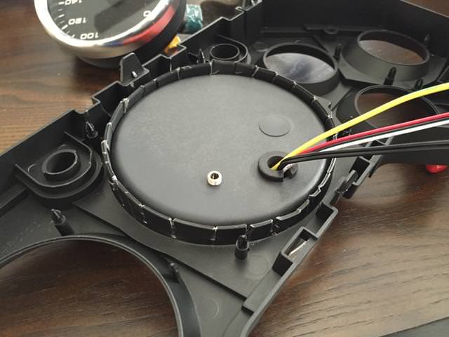
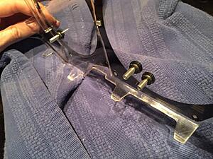
Remove any interferring white plastic standoffs on the base of the cluster. These will be obvious when piecing it together.
Run the wires through the (now) un-used bulb holes:
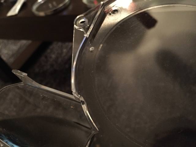
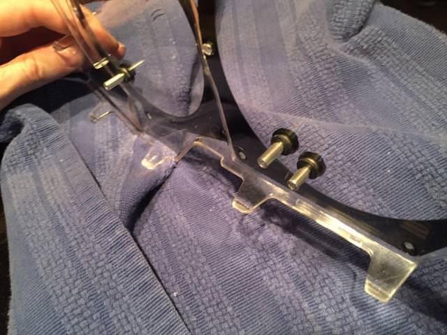
Once all the gauges are pressed in, I noticed that there are stubs on the edges of each gauge. I will need to drill out the clear lens to accept these protrusions. I put a bit of toothpaste on the tip of edge stub and then lined up the lens so I could see where I needed to drill:

The "drill here" mark it made on the lens:
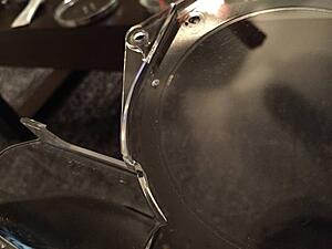
At this point you can re-install the lens and see that everything fits and lines up like OE
But then you will realize that you can't push the buttons on the programming for each gauge. I marked "eye-balled" where each of the buttons were with a sharpie, then removed the bezel and drilled it out to accept the speedhut rubber buttons and standoffs.
Drill slowwlllyyyyyy:
Buttons installed:
Standoffs put in place to reach the button on the gauge:
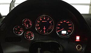
Screw all the items back together and you now have a fancy factory looking gauge setup with programmable shift lights and alarms:
Run the wires through the (now) un-used bulb holes:

Once all the gauges are pressed in, I noticed that there are stubs on the edges of each gauge. I will need to drill out the clear lens to accept these protrusions. I put a bit of toothpaste on the tip of edge stub and then lined up the lens so I could see where I needed to drill:
The "drill here" mark it made on the lens:
At this point you can re-install the lens and see that everything fits and lines up like OE
But then you will realize that you can't push the buttons on the programming for each gauge. I marked "eye-balled" where each of the buttons were with a sharpie, then removed the bezel and drilled it out to accept the speedhut rubber buttons and standoffs.
Drill slowwlllyyyyyy:

Buttons installed:
Standoffs put in place to reach the button on the gauge:
Screw all the items back together and you now have a fancy factory looking gauge setup with programmable shift lights and alarms:
 12-18-17, 12:42 PM
#2
Remove any interferring white plastic standoffs on the base of the cluster. These will be obvious when piecing it together.
Run the wires through the (now) un-used bulb holes:
Attachment 750459
Once all the gauges are pressed in, I noticed that there are stubs on the edges of each gauge. I will need to drill out the clear lens to accept these protrusions. I put a bit of toothpaste on the tip of edge stub and then lined up the lens so I could see where I needed to drill:
Attachment 750460
The "drill here" mark it made on the lens:
Attachment 750461
At this point you can re-install the lens and see that everything fits and lines up like OE
Attachment 750462
But then you will realize that you can't push the buttons on the programming for each gauge. I marked "eye-balled" where each of the buttons were with a sharpie, then removed the bezel and drilled it out to accept the speedhut rubber buttons and standoffs.
Drill slowwlllyyyyyy:
Attachment 750463
Buttons installed:
Attachment 750464
Standoffs put in place to reach the button on the gauge:
Attachment 750465
Screw all the items back together and you now have a fancy factory looking gauge setup with programmable shift lights and alarms:
Attachment 750466
Last edited by Esser; 12-18-17 at 01:01 PM.
The following 12 users liked this post by Esser:
b3delta (02-19-20),
box-o-aces (06-11-18),
briansfd (12-19-17),
cr-rex (12-19-17),
dfwrx7 (05-22-18),
and 7 others liked this post.


 12-18-17, 03:03 PM
#7
Rotary Enthusiast
iTrader: (32)

+1 on info about wiring the speedo and tach up, and the changes needed to the OEM circuit board/wiring to maintain warning lights and function of whatever random signals pass through the OE cluster now that the tach and speedometer are removed.
Great info though! Looks fantastic and would be a good option when the odometer flakes out and can't be resurrected.
I wonder, can Speedhut deliver the speedometer with a programmed mileage value or must it start at 0.0?
Great info though! Looks fantastic and would be a good option when the odometer flakes out and can't be resurrected.
I wonder, can Speedhut deliver the speedometer with a programmed mileage value or must it start at 0.0?
Last edited by jza80; 12-18-17 at 03:07 PM.
Trending Topics
12-18-17, 03:21 PM
#8
Amazing stuff! Love how it looks, very OEM+
I never liked the idea of having extra aftermarket gauges which do not match the OEM cluster (font, color, lighting etc...), but this way you can order everything from Speedhut and have all the gauges in the cluster and outside of the cluster match!
What can be done with the low water level light?
I never liked the idea of having extra aftermarket gauges which do not match the OEM cluster (font, color, lighting etc...), but this way you can order everything from Speedhut and have all the gauges in the cluster and outside of the cluster match!
What can be done with the low water level light?

 12-19-17, 10:54 AM
#13
Amazing stuff! Love how it looks, very OEM+
I never liked the idea of having extra aftermarket gauges which do not match the OEM cluster (font, color, lighting etc...), but this way you can order everything from Speedhut and have all the gauges in the cluster and outside of the cluster match!
What can be done with the low water level light?
I never liked the idea of having extra aftermarket gauges which do not match the OEM cluster (font, color, lighting etc...), but this way you can order everything from Speedhut and have all the gauges in the cluster and outside of the cluster match!
What can be done with the low water level light?
The Oil Pressure and Water Temp gauges will include their own sender and wires, you just need power and ground. All gauges include a joiner harness that lets power and ground to to them all, so you dont need to do repeat wiring for those. The fuel gauge uses one wire that you splice into on the harness that plugs into the cluster, I can get more pics of those. I'm running an LS3, and I have one wire for speedo and one wire for tach signal, but the stock rotary electronics are the same way....speedo uses the single wire and just needs to be programmed to get the speed accurate (handy when you do tire changes, speedo gets calibrated with the button on the gauge itself). Tach is one wire plug and play.
If you want to make life really easy you can get the GPS speedo, which will not need to be tied into anything, and will never need to be recalibrated no matter what wheel and tire combo you switch to.
https://www.speedhut.com/gauge/GR4-G...dometer-180mph
Last edited by Esser; 12-19-17 at 11:01 AM.
12-19-17, 11:40 AM
#14
Rotary Enthusiast
iTrader: (32)
Esser thank you for the ground breaking information. The basic physical installation seems very possible with a good looking and functioning outcome.
For those of us that are running rotaries, there will be a few additional things to think about. What comes to mind are:
The diagnostic lamp - in CA at least this is used during smog check, no light no pass. Not sure how this is activated, whether the signal passes through the tach or speedo board
The low oil lamp - maybe this can be wired into the Speedhut alarm lamp on the oil pressure gauge or tach (it looks like there are a couple unused lamps on the tach face?)
The low water lamp - same as oil? But less of a concern possibly if the gauge itself is highly accurate
The low fuel lamp - assume this can be programmed into the Speedhut gauge? (although this is probably not a critical feature for most)
The overrev buzzer - will this work if the OE gauges are removed? Does it matter if there is a shift light?
Airbag, alternator, seat belt, ABS, rear defog, and brake system function/warning lamps - will these still work?
Any other OE-specific functions that might be lost if the OE gauges are pulled out of the circuit?
12-19-17, 11:55 AM
#15
Esser thank you for the ground breaking information. The basic physical installation seems very possible with a good looking and functioning outcome.
For those of us that are running rotaries, there will be a few additional things to think about. What comes to mind are:
The diagnostic lamp - in CA at least this is used during smog check, no light no pass. Not sure how this is activated, whether the signal passes through the tach or speedo board
The low oil lamp - maybe this can be wired into the Speedhut alarm lamp on the oil pressure gauge or tach (it looks like there are a couple unused lamps on the tach face?)
The low water lamp - same as oil? But less of a concern possibly if the gauge itself is highly accurate
The low fuel lamp - assume this can be programmed into the Speedhut gauge? (although this is probably not a critical feature for most)
The overrev buzzer - will this work if the OE gauges are removed? Does it matter if there is a shift light?
Airbag, alternator, seat belt, ABS, rear defog, and brake system function/warning lamps - will these still work?
Any other OE-specific functions that might be lost if the OE gauges are pulled out of the circuit?
For those of us that are running rotaries, there will be a few additional things to think about. What comes to mind are:
The diagnostic lamp - in CA at least this is used during smog check, no light no pass. Not sure how this is activated, whether the signal passes through the tach or speedo board
The low oil lamp - maybe this can be wired into the Speedhut alarm lamp on the oil pressure gauge or tach (it looks like there are a couple unused lamps on the tach face?)
The low water lamp - same as oil? But less of a concern possibly if the gauge itself is highly accurate
The low fuel lamp - assume this can be programmed into the Speedhut gauge? (although this is probably not a critical feature for most)
The overrev buzzer - will this work if the OE gauges are removed? Does it matter if there is a shift light?
Airbag, alternator, seat belt, ABS, rear defog, and brake system function/warning lamps - will these still work?
Any other OE-specific functions that might be lost if the OE gauges are pulled out of the circuit?
I can't speak for the warning lights on the cluster for functionality, part of the reason i did this was to remove those. The gauges provide new warning lights that you can adjust to your liking for fuel, oil pressure, water temp, and an adjustable shift light. Thus making the OE ones obsolete.
In the event that you did want those to work, then you need to keep the speedo circuit board inside the cluster. But I'm not sure why you would as there would be two sets of warning lights going off at that point.
For the diagnostic lamp - I am looking at the FSM and I can't see a reason why it wouldn't work if the circuit film is left in tact, which is what I have done.
 12-19-17, 12:49 PM
#18
Rotary Enthusiast
iTrader: (32)
I can't speak for the warning lights on the cluster for functionality, part of the reason i did this was to remove those. The gauges provide new warning lights that you can adjust to your liking for fuel, oil pressure, water temp, and an adjustable shift light. Thus making the OE ones obsolete.
In the event that you did want those to work, then you need to keep the speedo circuit board inside the cluster. But I'm not sure why you would as there would be two sets of warning lights going off at that point.
For the diagnostic lamp - I am looking at the FSM and I can't see a reason why it wouldn't work if the circuit film is left in tact, which is what I have done.
How about the panel dimming? That circuit looks like it passes through the Speedo circuit. Although in my case I have it turned up to the max anyway so only the highest level is ever used so losing it would not be a big deal as long as the panel lamps worked at max brightness...
The more I think about this, the more I want to try this out with a spare cluster and hood bezel! It would be awesome to have a truly accurate water temperature gauge that is integrated in style. For that matter, the oil pressure gauge could be scrapped in favor of a low oil pressure lamp and fit a Speedhut boost gauge in that slot and remove the add-on look of a column or A-pillar mounted gauge.
Last edited by jza80; 12-19-17 at 12:55 PM.
12-19-17, 01:31 PM
#19
Do you think that there is sufficient space to retain the gauge circuit boards with the Speedhut gauges? They do look pretty thin.
How about the panel dimming? That circuit looks like it passes through the Speedo circuit. Although in my case I have it turned up to the max anyway so only the highest level is ever used so losing it would not be a big deal as long as the panel lamps worked at max brightness...
The more I think about this, the more I want to try this out with a spare cluster and hood bezel! It would be awesome to have a truly accurate water temperature gauge that is integrated in style. For that matter, the oil pressure gauge could be scrapped in favor of a low oil pressure lamp and fit a Speedhut boost gauge in that slot and remove the add-on look of a column or A-pillar mounted gauge.
There is only one circuit board (besides the circuit film) and it has a ribbon connector so it can be relocated. I have not tried to fit it in behind the speedhut's, but it would be tight as far as fitment.
12-19-17, 01:33 PM
#20
You will spend about $500 doing all the gauges, add another $200 if you get gauges with alarms. The GPS speedo will add on another $100 I believe.
I went with programmable alarms on all of mine except for the fuel. I did not get the GPS speedo. I got mine on the black Friday sale and got all of my gauges and sensors for $700.
12-19-17, 03:59 PM
#21
Rotary Enthusiast
iTrader: (32)
The Speedhuts have their own dimmer switch, so you can still dim the gauges. I ended up mounting my speedhut dimmer **** under the dash so it is hidden. You cannot migrate it to use the factory dimmer switch.
There is only one circuit board (besides the circuit film) and it has a ribbon connector so it can be relocated. I have not tried to fit it in behind the speedhut's, but it would be tight as far as fitment.
There is only one circuit board (besides the circuit film) and it has a ribbon connector so it can be relocated. I have not tried to fit it in behind the speedhut's, but it would be tight as far as fitment.
Good to know that the Speedhuts have their own provision for dimming, too.
Last edited by jza80; 12-19-17 at 06:05 PM.
12-19-17, 05:34 PM
#22
Part of the problem is the type of dimming control. The factory lighting (this is from an old memory and may be incorrect) is a pulsed ground signal i believe. The speedhut lighting is a rheostat to inverter. Unless the pulsed ground output can replace the rheostat, I am not well-versed enough in electronics to know how to integrate them.
12-21-17, 07:39 AM
#23
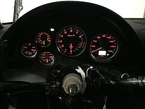
Gauges all wired up and installed. I do not have any of the circuit board from the factory speedometer, and it appears everything functions. All the stock lights still illuminate and the turn signals work fine. All HVAC controls and everything function. It is safe to delete that board when replacing the speedometer with speedhut.
The following users liked this post:
cloead (12-21-17)
