OMP Declassified
 03-15-10, 09:43 PM
#1

OMP Declassified
There has, in the past, been a lot of conjecture on how the OMP / MOP pump operates so I thought I would take everyone through it. Hope this will help some.
Reference the picture at bottom:
The Parts and what they do:

Reference the picture at bottom:
The Parts and what they do:
- Linear Stepper Motor - this simply steps a plunger in and out. How far the plunger is in or out is based upon the ECM commanded position.
- Valve Positioner - This moves in and out based upon the position of the linear stepper motor. It is in contact with the motor armature. The spring maintains contact with the motor armature. There is a "slope" or taper cut into the positioner which, depending upon where the motor has it positioned, will move the sector valve up or down.
- Worm Drive Gear and Worm Driven Gear - This is driven from the engine. It rotates the sector valve to align the oil holes up with either the front rotor housing oil injection port in the OMP housing or the rear rotor housing oil injection port in the OMP housing. The oil injection ports are 180 degrees apart so oil is never fed to both ports at the same time. The worm drive gear and worm driven gear rotate at all times the engine is running.
- Sector Valve and Sector Valve Needle - The sector valve is keyed to the worm driven gear and rotates in the housing bore at all times when the engine is running and feeds oil to the discharge ports one at a time when the holes in the valve align with the holes in the OMP housing. The Sector valve also moves up and down depending on the position of the linear motor and valve positioner and the rotational position of the sector valve. As the sector valve moves up, the needle is inserted into the sector valve bore and closes off the oil flow through the sector valve holes. So the deeper the linear stepper motor is pressing the valve positioner the more the sector valve falls into the taper allowing needle retraction from the sector valve and providing more oil flow when the holes align.
Position Transmitter - The transmitter is a linear 0 to 5 volt feed back to the ECM. It's sole function is to measure the position of valve that the linear stepper motor has set the valve. It is in contact with a tab that is a part of the valve positioner.
 03-15-10, 10:21 PM
#2
RX-7 Bad Ass
iTrader: (55)
Nice work! I've always wondered how that sucker works. Makes much more sense when it's apart  .
.
Thanks!
Dale
.Thanks!
Dale
03-16-10, 12:41 AM
#3
You say it is NOT a pump. I run the RA OMP adapter. The pressure to feed the OMP is ambient with 6 inch of head. How is the oil being injected into the engine if the OMP is not pumping?
There has, in the past, been a lot of conjecture on how the OMP / MOP pump operates so I thought I would take everyone through it. Hope this will help some.
Reference the picture at bottom:
The Parts and what they do:
Reference the picture at bottom:
The Parts and what they do:
- Linear Stepper Motor - this simply steps a plunger in and out. How far the plunger is in or out is based upon the ECM commanded position.
- Valve Positioner - This moves in and out based upon the position of the linear stepper motor. It is in contact with the motor armature. The spring maintains contact with the motor armature. There is a "slope" or taper cut into the positioner which, depending upon where the motor has it positioned, will move the sector valve up or down.
- Worm Drive Gear and Worm Driven Gear - This is driven from the engine. It rotates the sector valve to align the oil holes up with either the front rotor housing oil injection port in the OMP housing or the rear rotor housing oil injection port in the OMP housing. The oil injection ports are 180 degrees apart so oil is never fed to both ports at the same time. The worm drive gear and worm driven gear rotate at all times the engine is running.
- Sector Valve and Sector Valve Needle - The sector valve is keyed to the worm driven gear and rotates in the housing bore at all times when the engine is running and feeds oil to the discharge ports one at a time when the holes in the valve align with the holes in the OMP housing. The Sector valve also moves up and down depending on the position of the linear motor and valve positioner and the rotational position of the sector valve. As the sector valve moves up, the needle is inserted into the sector valve bore and closes off the oil flow through the sector valve holes. So the deeper the linear stepper motor is pressing the valve positioner the more the sector valve falls into the taper allowing needle retraction from the sector valve and providing more oil flow when the holes align.
Position Transmitter - The transmitter is a linear 0 to 5 volt feed back to the ECM. It's sole function is to measure the position of valve that the linear stepper motor has set the valve. It is in contact with a tab that is a part of the valve positioner.
03-16-10, 01:38 AM
#4
Junior Member

Join Date: Feb 2010
Location: E. Texas
Posts: 15
Likes: 0
Received 0 Likes
on
0 Posts
03-16-10, 02:12 AM
#5
DRIVE THE ROTARY SPORTS
iTrader: (5)
Join Date: May 2003
Location: CA (Bay Area)
Posts: 4,150
Likes: 0
Received 0 Likes
on
0 Posts
I always thought the motor was sucking oil through the port, and the oil metering pump did simply that... meter the amount of flow ALLOWED to the engine. I was under the impression that it was not pressurized (in stock form) and that is why you simply needed a gravity feed (tank 6" above the omp) if using an external tank.
03-16-10, 03:47 AM
#6
This raises an interesting question as to how the OMP oils the engine while under boost. The foregoing discussion suggests the OMP needs a source of oil under pressure, which will be true unless the OMP also functions as a positive displacement pump.
03-16-10, 06:42 AM
#7
There were some significant errors in what I stated on the operation of the OMP. After I hastily wrote the original thread entry I mocked up the OMP and ran it on the bench with oil revealing that it does pump oil. I apologies for this and have provided the necessary corrections below:
The Parts and what they do:
The Parts and what they do:
- Linear Stepper Motor - this simply steps a plunger in and out. How far the plunger is in or out is based upon the ECM commanded position.
- Valve Positioner - This moves in and out based upon the position of the linear stepper motor. It is in contact with the motor armature. The spring maintains contact with the motor armature. There is a "slope" or taper cut into the positioner which, depending upon where the motor has it positioned, will change the length of the Worm Driven Gear and Sector Valve stroke.
- Worm Drive Gear and Worm Driven Gear - This is driven from the engine. It rotates the sector valve to align the oil holes with either the oil supply or oil discharge in the OMP body. The worm drive gear and worm driven gear rotate at all times the engine is running. The worm driven gear has two cam followers; as the gear rotates it moves up and down. The followers ride on the Valve Positioner.
- Sector Valve and Sector Valve Needle - The sector valve is keyed to the worm driven gear and rotates in the housing bore at all times when the engine is running. The Sector valve also moves up and down by the two cam followers on the Driven Gear. The stroke length of the sector valve is determined by the where the followers track on the Valve Positioner tapered area. The Sector Valve�s ports rotate to align with either oil fill ports or oil discharge ports. As the sector valve moves down in the bore the fill ports are aligned and oil is drawn into the Sector Valve / Needle bore. The Sector valve continues to rotate and then begin to move up on the cam causing the needle to move into the bore of the sector valve and compressing the oil previously drawn in. At this time the sector valve holes are aligned with the OMP discharge ports and oil is forced to the engine.
- Position Transmitter - The transmitter is a linear 0 to 5 volt feed back to the ECM. It's sole function is to measure the position of valve that the linear stepper motor has set the valve. It is in contact with a tab that is a part of the valve positioner.
Trending Topics
03-16-10, 12:15 PM
#9
Racecar - Formula 2000
...
The OMP is an oil pump; the engine oil is gravity fed into the OMP through the engine front cover. The up and down movement of the Sector Valve causes a pumping action between the Sector Valve and Sector Valve Needle. The sequence of rotational position in relation of the up and down movement and the location of the oil inlet and discharge ports is the pumping action.
The OMP is an oil pump; the engine oil is gravity fed into the OMP through the engine front cover. The up and down movement of the Sector Valve causes a pumping action between the Sector Valve and Sector Valve Needle. The sequence of rotational position in relation of the up and down movement and the location of the oil inlet and discharge ports is the pumping action.
Dave
03-16-10, 12:18 PM
#10
Have you ever heard of No Child Left Behind? Apparently not because you must have been one of those who were left behind. The whole point is to:
(a) read
(b) think
(c) and test out part (b).
It is not to accept things at face value. In fact, look at the original poster, he has now revised his post to indicate that the OMP is a "pump".
(a) read
(b) think
(c) and test out part (b).
It is not to accept things at face value. In fact, look at the original poster, he has now revised his post to indicate that the OMP is a "pump".

 12-05-10, 11:51 AM
#15
I thought I'd post this chart from a dyno run here in this thread.
This is a chart of OMP "Oil" data as reported by a PFC. It is a 3rd gear pull on a '94 FD with sequential twins, using only its original OMP for apex seal lubrication. RPM, manifold pressure, TPS voltage, and OMP "Oil" value are shown. TPS and OMP were carefully scaled in the chart to represent their achievable minimum and maximum values.
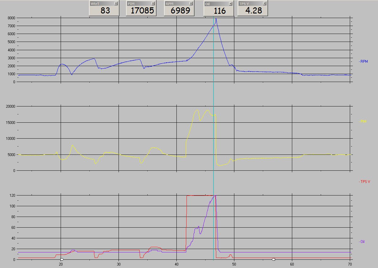
I am unsure what the units for "Oil" really are. They may be related to the OMP position sensor voltage. The lowest value I have seen is 14 (mostly at idle and very low rpm/throttle/load) and the highest value I have seen is 120 at about 8000rpm. It may work out that the Oil value is 0 - 120 with 0 being completely closed (least amount of flow mechanically possible) and 120 being full open. You can see that above all else the oil delivery is based on rpm and manifold pressure. On the series 5 FC3S oil delivery was based on rpm and engine airflow as measured by a vane airflow meter.
This is a chart of OMP "Oil" data as reported by a PFC. It is a 3rd gear pull on a '94 FD with sequential twins, using only its original OMP for apex seal lubrication. RPM, manifold pressure, TPS voltage, and OMP "Oil" value are shown. TPS and OMP were carefully scaled in the chart to represent their achievable minimum and maximum values.
I am unsure what the units for "Oil" really are. They may be related to the OMP position sensor voltage. The lowest value I have seen is 14 (mostly at idle and very low rpm/throttle/load) and the highest value I have seen is 120 at about 8000rpm. It may work out that the Oil value is 0 - 120 with 0 being completely closed (least amount of flow mechanically possible) and 120 being full open. You can see that above all else the oil delivery is based on rpm and manifold pressure. On the series 5 FC3S oil delivery was based on rpm and engine airflow as measured by a vane airflow meter.
12-15-10, 03:40 PM
#16
DRIVE THE ROTARY SPORTS
iTrader: (5)
Join Date: May 2003
Location: CA (Bay Area)
Posts: 4,150
Likes: 0
Received 0 Likes
on
0 Posts
I'm wondering... externally the 94 FD pump and 20b cosmo pump look identical aside from a line coming out of one of the fittings (normally a blank on the 13b). There is a 4th fitting on there as well  maybe mazda was thinking ahead a little
  . Anyone have info on how the pump distributes the oil? Does it individually meter it for each rotor line, or does it just dump X amount of oil and assume each rotor will take an equivalant amount? If thats the case, then the pumps would be identical, just the software would multiply the total metered output by 3 (or 4 in the case of using all available ports )
maybe mazda was thinking ahead a little . Anyone have info on how the pump distributes the oil? Does it individually meter it for each rotor line, or does it just dump X amount of oil and assume each rotor will take an equivalant amount? If thats the case, then the pumps would be identical, just the software would multiply the total metered output by 3 (or 4 in the case of using all available ports )
12-15-10, 07:24 PM
#17
I thought I'd post this chart from a dyno run here in this thread.
This is a chart of OMP "Oil" data as reported by a PFC. It is a 3rd gear pull on a '94 FD with sequential twins, using only its original OMP for apex seal lubrication. RPM, manifold pressure, TPS voltage, and OMP "Oil" value are shown. TPS and OMP were carefully scaled in the chart to represent their achievable minimum and maximum values.
I am unsure what the units for "Oil" really are. They may be related to the OMP position sensor voltage. The lowest value I have seen is 14 (mostly at idle and very low rpm/throttle/load) and the highest value I have seen is 120 at about 8000rpm. It may work out that the Oil value is 0 - 120 with 0 being completely closed (least amount of flow mechanically possible) and 120 being full open. You can see that above all else the oil delivery is based on rpm and manifold pressure. On the series 5 FC3S oil delivery was based on rpm and engine airflow as measured by a vane airflow meter.
12-15-10, 09:02 PM
#19
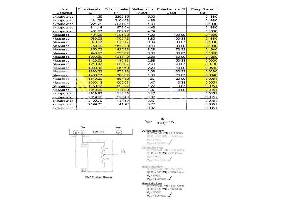
Here is some data both measured and extrapolated. The extrapolated data is beyond the capability of the OMP's potentiometer. Note I put 0-100% related to the pot's full stroke. Also note that the first and last zones of the potentiometer's range there is no change in pump stroke; INTERESTING the pump variance is from 20% to 80% of the pot's range. This is why I was curious about the VMOP related to the count. Now in the data I have collected during tuning sessions I have seen 1.14V at low loads to 4.06V at high loads on VMOP; there is a slight difference in calculated voltages and measured voltages but they align quite well.
12-16-10, 11:08 AM
#21
Where I'm trying to go with this is to determine if a time offset between the "count" and VMOP voltage reading exists. This will tell us that the "count" is the command from the ECU and the VMOP is the reacted position. So I'm thinking the count may be the stepper motor sequencing through the range of movement. The stepper motor looks to be a four pole design (six wires) and if half steps are utilized there will be a count of eight per motor revolution. I could count the gear ratio of my mikuni pump to get a total revolution count for the motor - open to close. So, in your observation a count of 14 to 120 may be the 20% to 80% range the pump changes oil flow. May want to review this site for stepper motor 101..
http://www.imagesco.com/articles/picstepper/02.html
As a side note the oil flow never completely turns off; as long as the E-Shaft turns the OMP will provide oil.
http://www.imagesco.com/articles/picstepper/02.html
As a side note the oil flow never completely turns off; as long as the E-Shaft turns the OMP will provide oil.
12-16-10, 01:27 PM
#22
So I'm thinking the count may be the stepper motor sequencing through the range of movement. The stepper motor looks to be a four pole design (six wires) and if half steps are utilized there will be a count of eight per motor revolution. I could count the gear ratio of my mikuni pump to get a total revolution count for the motor - open to close. So, in your observation a count of 14 to 120 may be the 20% to 80% range the pump changes oil flow.
May want to review this site for stepper motor 101..
http://www.imagesco.com/articles/picstepper/02.html
http://www.imagesco.com/articles/picstepper/02.html
As a side note the oil flow never completely turns off; as long as the E-Shaft turns the OMP will provide oil.
12-16-10, 05:17 PM
#23
OK, here is the best I can do from some of the files I have. I don't think the time hacks in the PFC lend enough resolution to really tell if OIL Leads VMOP. I multiplied VMOP times 20 so the curves were comparable. What are your thoughts???

12-18-10, 09:55 AM
#25
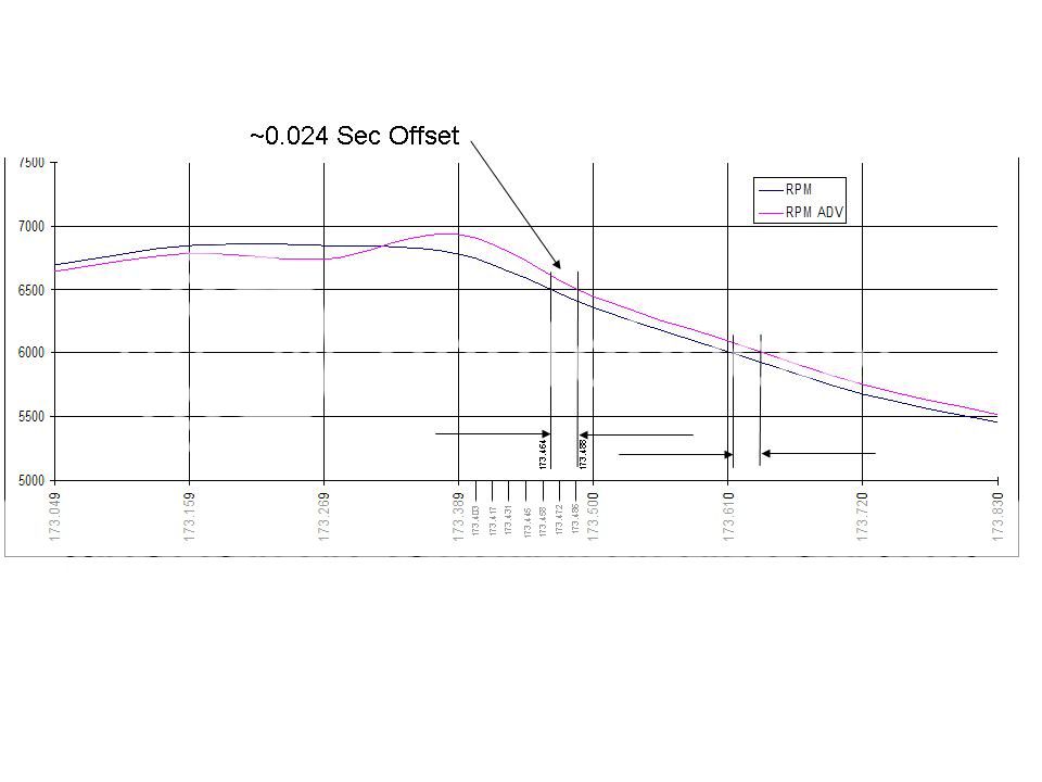
Possible the sampling is at the same time but processing and logging is offset. Consider the following chart; One RPM log is from the Basic listing and the other is from the Advanced. For a given time hack in the data stream the RPM are different. When plotted there is an offset of about 0.024 seconds. This appears consistent in increasing and decreasing trends. The Advanced logging appears to be lagging. If consistent between the basic and advanced sensor logging the "OIL" is occuring about 0.024 seconds earlier than the log times. Regardless, this is still not proven by test. The only real way to validate this is to put a scope on the ECU which is beyond what I can do at this time.
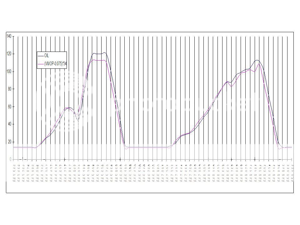
Now in the following plot I have normalized the two (VMOP and OIL) amplitudes but the data occurence has not changed. There is basically the same offset seen in the two RPM comparisons. I would submit that OIL and VMOP are the same but only displayed differently.
Now in the following plot I have normalized the two (VMOP and OIL) amplitudes but the data occurence has not changed. There is basically the same offset seen in the two RPM comparisons. I would submit that OIL and VMOP are the same but only displayed differently.

Thread
Thread Starter
Forum
Replies
Last Post