When you click on links to various merchants on this site and make a purchase, this can result in this site earning a commission. Affiliate programs and affiliations include, but are not limited to, the eBay Partner Network.
I'll be pulling my instrument cluster in a few days to see about getting it fixed.
At this time the tach does not work, although it does sporadically work for a little bit from time to time for brief moments.
The speedo does work when moving but at a stop it reads 20kmh and sometimes if I rev the engine the speedo needle tracks as if it's a tachometer.
Also the odometer screen does not work.
So I'll be pulling the cluster to check it all over in a few days.
What I'm wanting to know...is while I have the cluster on a workbench I want to calibrate the speedo to read MPH instead of KPH.
I know how to do so using DaleClark's guide by adjusting the poteniometer.
But I'm wanting to adjust this while it's on the bench.
My RX7 is RHD so it's a little harder to adjust it while it's in the car.
I have access to a signal generator I just need to know what the vss signal voltage is to the cluster and the pulse number per second for 60mph.
I'm assuming the signal is in a sine wave form.
I've searched but haven't found a definitive answer yet.
Any help?
Thanks!
I thought about doing something similar at one point but it's a lot of work when you can just plug it into the car and drive around the block . I don't understand why a RHD car would be harder to adjust in the car, should be the same process.
Ok, with all the acolades from Dale I forgot to add in one key piece of information. What is the AC voltage output of the sensor?
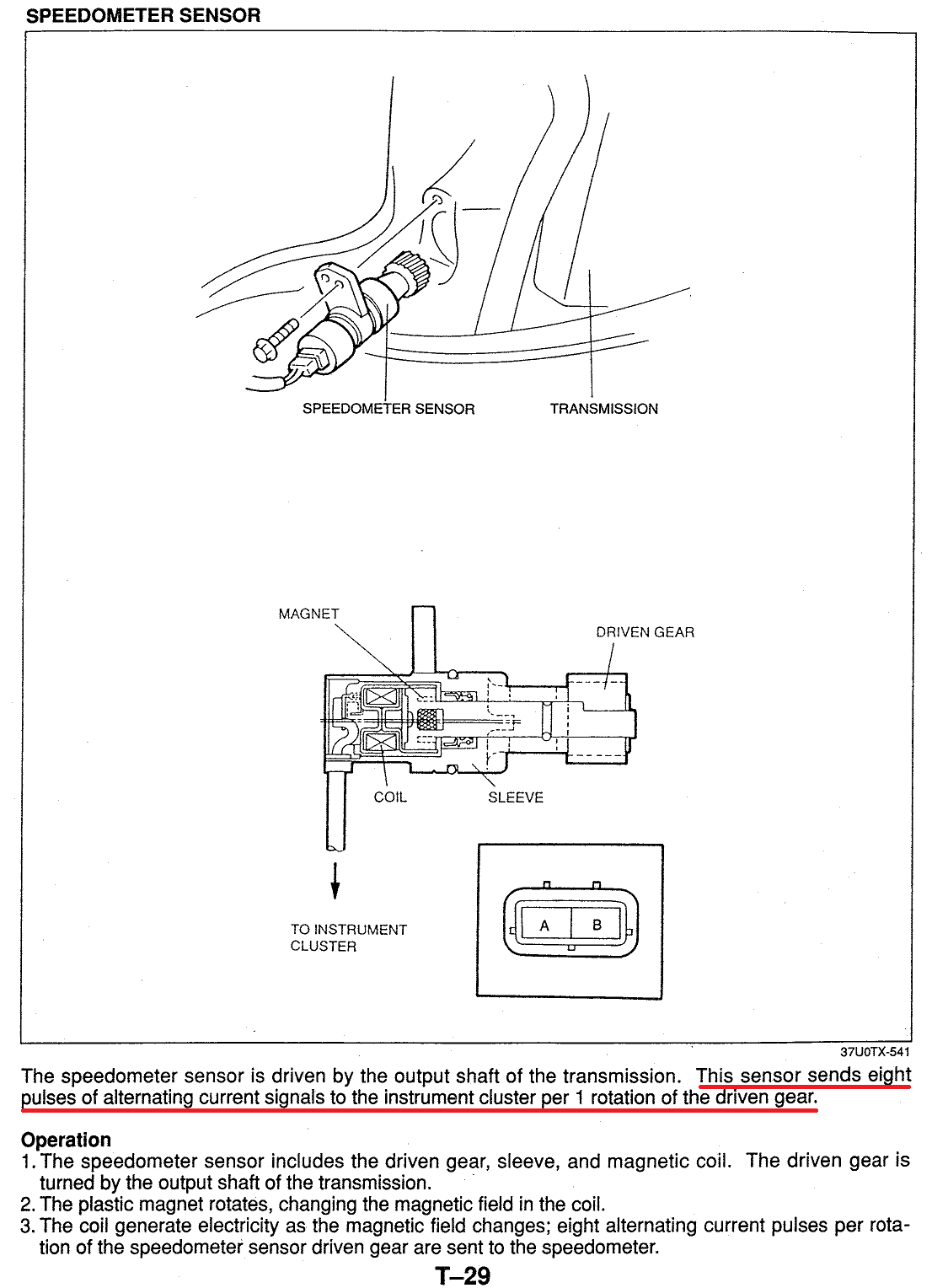
This vehicle speed sensor (revolution sensor) is for the automatic transmission power train module, I'm assuming the speedometer speed sensor is similar. As I couldn't find any information on the speedometer sensor it's as good a place as any to start setting up the function generator. If anyone knows the AC voltage or discovers it please post your results. (This is a wrong assumption folks, read the rest of the posts!)
Last edited by mdp; 11-14-17 at 11:47 AM.
Reason: Added in this is a wrong assumption
MDP, you are the MVP!
Thank you so much!
Thanks to Dale also for all your contributions. I'll be using your guide to make the odometer read miles over kilometers as well.
Ok, with all the acolades from Dale I forgot to add in one key piece of information. What is the AC voltage output of the sensor?
This vehicle speed sensor (revolution sensor) is for the automatic power train module, I'm assuming the speedometer speed sensor is similar as I couldn't find any information on the speedometer sensor. It's as good a place as any to start setting up the function generator. If anyone knows the AC voltage or discovers it please post your results.
I was able to track down the VSS info in the Body Electrical book.
It appears to vary between 2 and 3v during operation. I assume I can have my sine wave vary between those two voltages and it'll drive the speedometer with a pulse of 8200 per minute.
That is the automatic transmission speed sensor it is a three wire sensor and probably not the same. we are looking for Connectors C1-01 pins 3C and 3A not 1l. They don't say if the meter is set to AC or DC
The only clue we have is if you spin the sensor and measure it with voltmeter (I'm assuming on DC ) it is under 5 volts.
You measure a two wire VSS as AC not DC.
Ours is a two wire setup and this video shows how to test the function of the sensor. But doesn't show what a standard voltage fluctuation would be.
Now the cluster shouldn't really care what the voltage is per say, but rather the pulses of variation in the voltage, the rises and drops in voltage.
I'd love to know what real world the cluster see's but I'm guessing if I keep the fluctuation below 5v and see what it does, I can adjust from there.
Once I get 102km on the speedo at 8200 ppm I know I'll be at the right point.
Yes, I know. That is why I'm confused. Every where else in the factory manuals whenever they measure voltage with a meter using AC they emphasize the meter must be on AC in the instructions and they put a footnote stating the meter must be on AC. As you can see on this page they make no mention of AC! So, we are left with "What were they thinking?" I think your approach is sound. Don't forget to report back to all of us what you find.
Drumroll please!
For your viewing pleasure here is the output of the speedometer sensor. The + and - probe wires were attached to the two plug outputs.
It's sine waveish and it's about 5v peak to peak. Kudos to the Miata folks for coming up with this, apparently the 2000-2005 Miatas use the same sensor with a different gear. For example, hereis a link where a RX-7owner used our FD sensor to drive a Miata speedometer he installed in his second gen RX-7!
Last edited by mdp; 11-14-17 at 11:58 AM.
Reason: Added thanks to the Miata Folks
I just wanted to add one little note here, notice as the period gets shorter (ie the sensor is spinning faster) the peak to peak voltage gets larger. At the beginning of the ocillosope trace the period is longer and the peak to peak voltage is about 4.25 volts. At the end of the trace the period is shorter and the peak to peak voltage is 5.5 volts. Which make you wonder what the peak to peak voltage is when the thing is spinning a an indicated 100 mph!
IC4 compares 2 different signals to generate the Tachometer signal and Speed signal from the TAM input and Speed Sensor input, respectively. It's good to see a connection!
 11-12-17, 09:24 PM

 . I don't understand why a RHD car would be harder to adjust in the car, should be the same process.


 ) it is under 5 volts.