just got done figuring out how to fix an FD odometer
 11-22-06, 06:00 PM
#1
Full Member
Thread Starter
just got done figuring out how to fix FD odometer
i just got done taking my instrument cluster apart and looking for a fix for the odometer failure. what i found was simple. once you get the cluster pod off and taken apart, you can look at the front side of the gauge behind the actual face and see several capacitors. there were two on my board that had black marks under them where they solder to the board. i then unsoldered the actual speedometer motor that turns the needle on the gauge and pulled the speedo off so all i had left was the board with the odometer screen attached. from there i could remove and replace the capacitors that were bad. they looked like they had burn marks under them but it is actually electrolyte. the type of capacitors used on this board are polarity sensitive electrolytic capacitors. inside they have the electrodes and a paper dielectric soaked in a fluid called the electrolyte. over time these capacitors have a tendency to leak this fluid and cause the capacitor to fail. once they were replaced i installed everything and put it in the car and it works flawlessly now. if there is enough interest in this thread i can post an in depth tutorial with pictures.
matt
matt
 11-22-06, 08:52 PM
#2
Not the company
There was way too much technical mumbo-jumbo words in there that i don't understand but i'd be interested in seeing the pics anyway, and i'm glad that you fixed the problem!
The following users liked this post:
rousu (11-17-18)
11-22-06, 11:14 PM
#4
Full Member
Thread Starter
Ok, it's 11:30 pm and I'm bored so I'll do the full tutorial and get it over with.
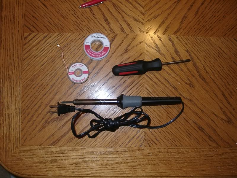
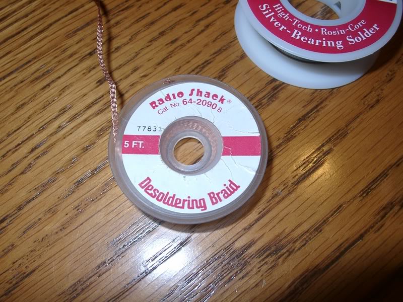
To start out, remove the cluster and gauge hood from the dash. Then remove the cluster from the back of the hood by removing 4 screws. The next thing that is needed is the proper tools. You will need a soldering iron (lower wattage preferred), some good electronic solder, some desoldering braid, and a phillips head screw driver.
After you have acquired the proper tools start by removing the clear plastic cover from the instrument cluster. This is done by removing two screws (in red) and popping the black clips down on the top and bottom of the cluster.

This is the view after removing the cover from the cluster
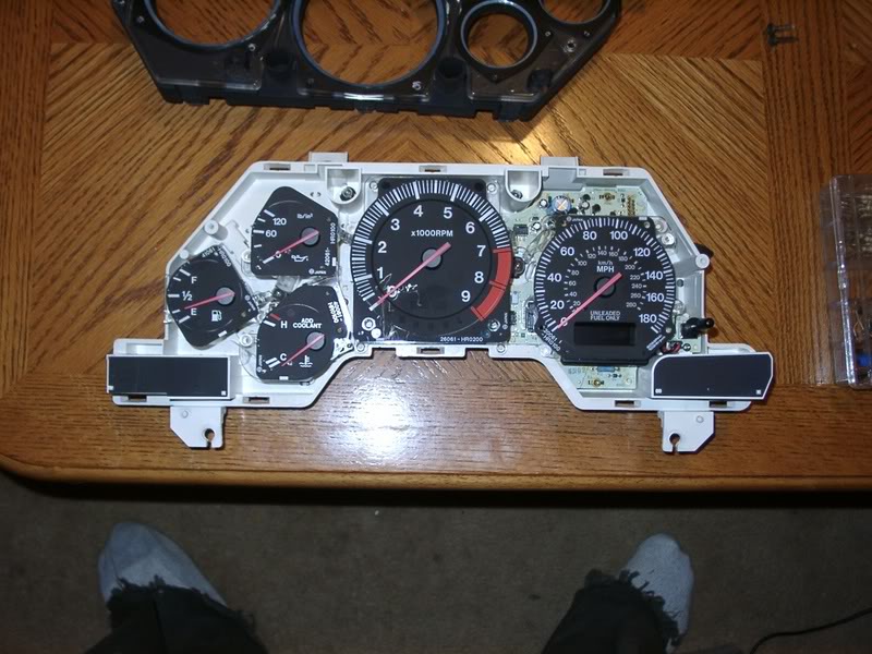
Now you are going to want to remove both the tachometer, the speedometer/odometer unit, and the connection that goes from the back of the cluster to the speedometer unit. The first thing is to remove the three screws that hold on the tachometer (in red). After you remove the tachometer, you will want to remove the one screw holding a cover over the electrical connection that goes to the speedometer (in green). Now turn the cluster over and remove the screw holding the trip reset button to the cluster. After you have disconnected the lead to the speedo and removed the trip reset button, you will want to remove the five screws holding the speedo to the cluster (in yellow).
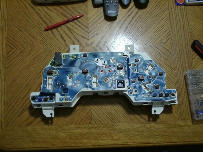
After all of this is removed, now you get the speedo out of the cluster.
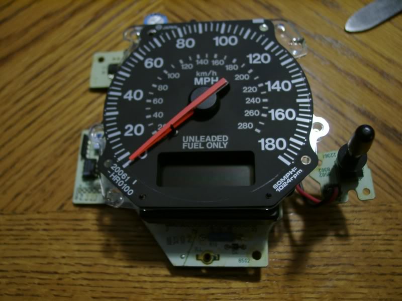
When you get the speedo out, you are going to remove the unit that includes the face and needle motor. This unit is easily removed (with basic soldering skills) heating the solder joints (in red) and using the desoldering braid to soak up the used solder. The best method to remove solder is to first heat the solder joint, and then place the desoldering braid over the solder joint and then placing the soldering iron tip over the joint, which is under the braid. It will require moving the braid around the connection until there is no solder left on this connection. Now be patient, if this is done correctly, after you remove the two (I think) screws located between these four connections, the motor and face will just fall off.
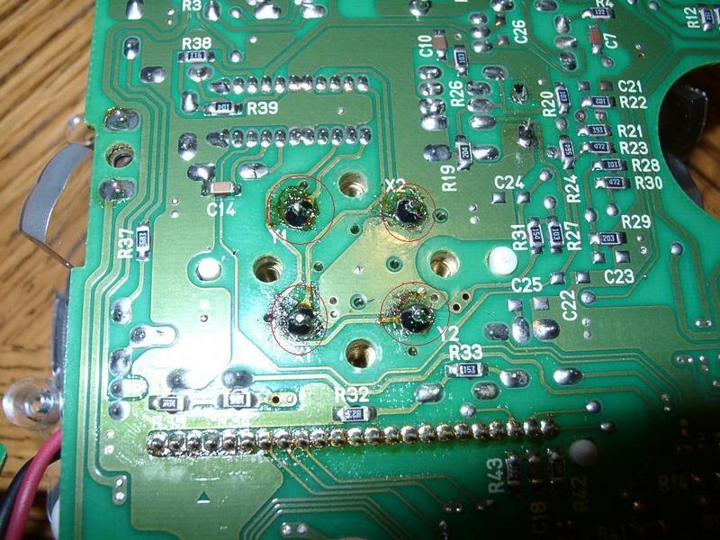
Once the motor and face are removed, here is the birds eye view.
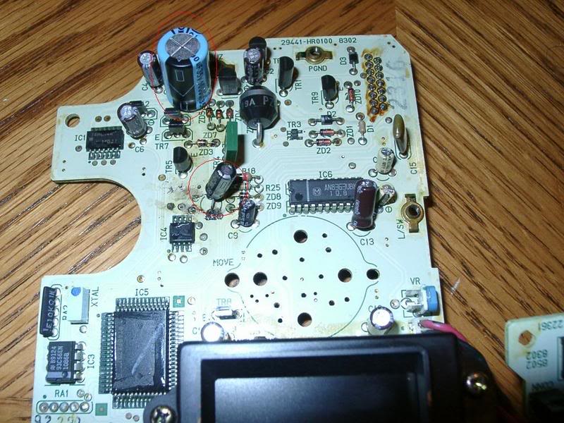
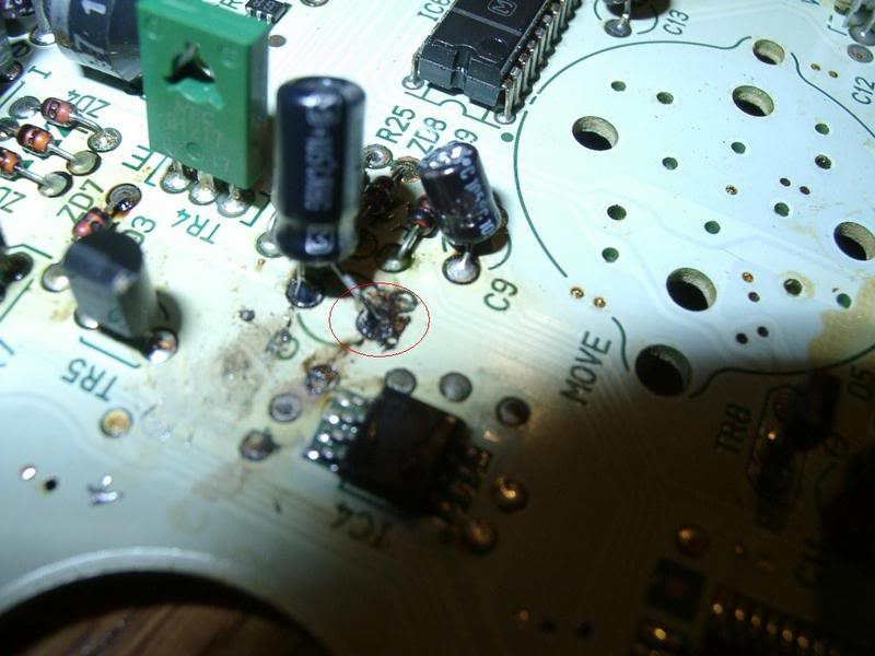
Now you can look around real good and see what is loose/burned/leaking. I had two capacitors that had leaked (explained in my previous post) and in the following picture I have already replaced the capacitors. One of the caps I replaced is substantially larger than the original one (I was too anxious to wait for one to be ordered). Below I have pictured what the burn (leak) will look like. I had already soldered on the new one but the black burn mark is still there. The burn will be in red. Just look around, there isn't that much that can go wrong with a printed circuit board, usually its bad components.
Once you find the problem components (I hope yours is as easy as mine) remove the bad component and replace it. Removing an electronic part is the same as removing the speedo motor and face. Just hold the braid over the connection and let it suck up the solder. If you don't have a large electronic background, take the parts to your local Radio Shack. The guys (or gals) that work at these places seem to be smart enough to work at an electronics store. If they don't have it in stock, they can probably get it pretty quick. I have not tested the cluster with missing components so I would not drive the car with parts missing.
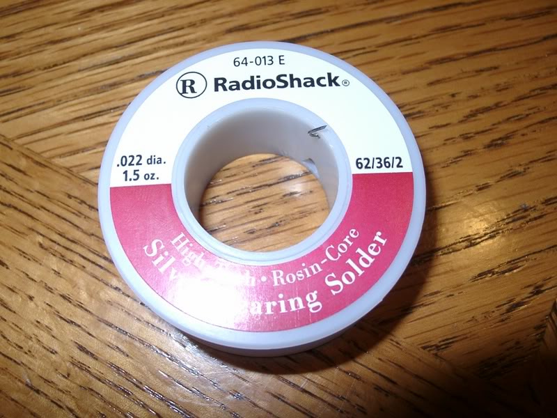
When you get the parts, installation is pretty straight forward. Clean the board real good with some rubbing alcohol and make sure it is dry. Heat the connections and push the component through the holes. Be careful when applying solder, some of the connections are pretty close together so you might wind up soldering more than one trace together. Use a good high quality silver rosin core solder. Its cheap enough to do right the first time. And don't use one of those huge gun type soldering irons. Those things get too hot and run the risk of damaging the board or other components on it. I use the base model 30 watt pen style soldering iron with the tip shaped pretty fine. This will allow you to get into those tight places without melting everything. When it comes to soldering, more heat isn't always better. Make sure the tip is tinned (thinly coated with solder) and free of pits. Have a sponge or wet towel laying around handy so you can wipe excess solder off the tip. This prevents the nightmarish drip on some random location on the board.
The rest of the job is the reverse of removal and disassembly. Use good judgement, and if you find all the faulty parts, do good solder joints, and make sure to keep your work and area clean and organized, your odometer will spring back to life.
Matt
To start out, remove the cluster and gauge hood from the dash. Then remove the cluster from the back of the hood by removing 4 screws. The next thing that is needed is the proper tools. You will need a soldering iron (lower wattage preferred), some good electronic solder, some desoldering braid, and a phillips head screw driver.
After you have acquired the proper tools start by removing the clear plastic cover from the instrument cluster. This is done by removing two screws (in red) and popping the black clips down on the top and bottom of the cluster.
This is the view after removing the cover from the cluster
Now you are going to want to remove both the tachometer, the speedometer/odometer unit, and the connection that goes from the back of the cluster to the speedometer unit. The first thing is to remove the three screws that hold on the tachometer (in red). After you remove the tachometer, you will want to remove the one screw holding a cover over the electrical connection that goes to the speedometer (in green). Now turn the cluster over and remove the screw holding the trip reset button to the cluster. After you have disconnected the lead to the speedo and removed the trip reset button, you will want to remove the five screws holding the speedo to the cluster (in yellow).
After all of this is removed, now you get the speedo out of the cluster.
When you get the speedo out, you are going to remove the unit that includes the face and needle motor. This unit is easily removed (with basic soldering skills) heating the solder joints (in red) and using the desoldering braid to soak up the used solder. The best method to remove solder is to first heat the solder joint, and then place the desoldering braid over the solder joint and then placing the soldering iron tip over the joint, which is under the braid. It will require moving the braid around the connection until there is no solder left on this connection. Now be patient, if this is done correctly, after you remove the two (I think) screws located between these four connections, the motor and face will just fall off.
Once the motor and face are removed, here is the birds eye view.
Now you can look around real good and see what is loose/burned/leaking. I had two capacitors that had leaked (explained in my previous post) and in the following picture I have already replaced the capacitors. One of the caps I replaced is substantially larger than the original one (I was too anxious to wait for one to be ordered). Below I have pictured what the burn (leak) will look like. I had already soldered on the new one but the black burn mark is still there. The burn will be in red. Just look around, there isn't that much that can go wrong with a printed circuit board, usually its bad components.
Once you find the problem components (I hope yours is as easy as mine) remove the bad component and replace it. Removing an electronic part is the same as removing the speedo motor and face. Just hold the braid over the connection and let it suck up the solder. If you don't have a large electronic background, take the parts to your local Radio Shack. The guys (or gals) that work at these places seem to be smart enough to work at an electronics store. If they don't have it in stock, they can probably get it pretty quick. I have not tested the cluster with missing components so I would not drive the car with parts missing.
When you get the parts, installation is pretty straight forward. Clean the board real good with some rubbing alcohol and make sure it is dry. Heat the connections and push the component through the holes. Be careful when applying solder, some of the connections are pretty close together so you might wind up soldering more than one trace together. Use a good high quality silver rosin core solder. Its cheap enough to do right the first time. And don't use one of those huge gun type soldering irons. Those things get too hot and run the risk of damaging the board or other components on it. I use the base model 30 watt pen style soldering iron with the tip shaped pretty fine. This will allow you to get into those tight places without melting everything. When it comes to soldering, more heat isn't always better. Make sure the tip is tinned (thinly coated with solder) and free of pits. Have a sponge or wet towel laying around handy so you can wipe excess solder off the tip. This prevents the nightmarish drip on some random location on the board.
The rest of the job is the reverse of removal and disassembly. Use good judgement, and if you find all the faulty parts, do good solder joints, and make sure to keep your work and area clean and organized, your odometer will spring back to life.
Matt
Last edited by dgeesaman; 10-23-15 at 06:16 PM. Reason: Changed photobucket links to forum attachments
The following users liked this post:
thad (08-31-21)
11-23-06, 09:37 AM
#7
RX-7 Bad Ass
iTrader: (55)
Excellent! I know a number of people have had dead odometers and ended up getting another odometer with incorrect mileage. This is the RIGHT way to do it.
Thanks a bunch for solving this problem!
Dale
Thanks a bunch for solving this problem!
Dale
Trending Topics
11-23-06, 01:13 PM
#8
Full Member
Thread Starter
well, i have two used capacitors here. If you look in the picture of the board without the face on it, you will see two replaced capacitors circled in red. the top one is the huge blue one. that is a 1000 micro farad 6.3 volt 105 degree centigrade capacitor. the smaller black one circled in red is a 10 micro farad 50 volt 105 degree centigrade cap. both of these are brown in color with a silver stripe down the side noting the negative lead. the voltage is not as important as long as you don't exceed the voltage listed on the cap. the problem with the voltage rating is that the higher the voltage it can withstand, the larger the cap. i would try to order the exact part because of space issues. also, this might not be the only problem parts, but these are the ones i found to be faulty.
11-24-06, 08:52 PM
#9
Full Member
Thread Starter
I wish someone could archive this somewhere. Mine is still working and this might help someone save a few hundred bucks. That and it has pretty pictures.
11-25-06, 01:26 AM
#12
RX-7 Bad Ass
iTrader: (55)
Again, great stuff!
For those of us that are electronics-retarded, do you have links or part numbers for the 2 caps you used? I can solder, desolder, know how components work, etc. but looking through Digi-Key my mind got stuck in a whirlpool of weirdo terminology for caps. "Uh, I want the ones that look like a two-legged barrel, please".
Thanks for the great work!
Dale
11-25-06, 10:01 AM
#14
Full Member
Thread Starter
yes, changing every cap would be a good idea, but i have limited funds so more replacements would require tapping into my food money. i used to own a dsm so i am no stranger to reading and writing tutorials. i'll never miss the car but i learned a lot about working on things and being frugal while fixing something.
11-26-06, 01:30 PM
#15
Senior Member
Join Date: Nov 2001
Location: Oak Ridge, TN
Posts: 749
Likes: 0
Received 0 Likes
on
0 Posts
ok, so i replaced the capacitor that was blown out with the exact 1000microfarad cap that you used and no go! what is a way i can test each cap to see if they are doing their job?
11-26-06, 01:56 PM
#16
Full Member
Thread Starter
there is no real way to test a capacitor without expensive testers. another thing to be careful about is making sure you don't overheat the capacitor. if you are trying to get the cap to go through the board and it isn't cooperating hold off and let it cool. i know most electronic parts are very heat sensitive so if it gets hot you fry it. make sure you find all the bad components or it still might not work. i overheated one of the parts i replaced and the odometer worked for about five minutes and then it died again. also, make sure you install the capacitor in the correct direction. electrolytic capacitors are polarity sensitive. if you are replacing the top capacitor and using the huge blue one i have in my picture, the polarity stripe should go down. if you look carefully at the little diagram on the board where the capacitor goes you will notice a little negative symbol beside one of the holes (the lower hole). if you install it backwards it is instant ownage. i wish there was a way to edit my tutorial post because i forgot to mention the importance of polarity. if i could get a moderator to edit the post or something to mention the installation direction, that would be great.
11-28-06, 10:10 PM
#17
Newbie
iTrader: (9)
Join Date: Feb 2002
Location: MI
Posts: 1,171
Likes: 0
Received 0 Likes
on
0 Posts
So does anyone have any idea what the different capacitors are for? I had a friend who repairs circuit boards rather frequently replace the two capacitors that turbo blue did and it unfortunatly didn't fix my odometer problem  . If noone else has any good info i'll probably just have him replace them all as capacitors aren't TERRIBLY expensive. Would be nice to rule some of them out though.
. If noone else has any good info i'll probably just have him replace them all as capacitors aren't TERRIBLY expensive. Would be nice to rule some of them out though.
12-28-06, 12:56 AM
#18
808
iTrader: (1)
Join Date: Jan 2005
Location: San Antonio/Burnet
Posts: 93
Likes: 0
Received 0 Likes
on
0 Posts
Just replaced the 1000 microfarad capacitor with the same capacitor that Turbo Blue used from Radio Shack with positve results. Odometer is still displaying as advertised. Pulling the instrument cluster was a challenge but with a tug here and there it finally came out. After removing the cluster I just followed the instruction that Turbo Blue posted with the exception of removing the speedometer from the circuit board. The capacitor was accessible for replacement. Turbo Blue.....if you're ever in San Antonio let me now. I owe you a beer!
01-14-07, 04:45 PM
#21
Full Member

please send information.
Please send the detailed info to the rx7 email list, or tell us where to find it.
Marc, 94 rx7
Marc, 94 rx7
Originally Posted by turbo blue
i just got done taking my instrument cluster apart and looking for a fix for the odometer failure. what i found was simple. once you get the cluster pod off and taken apart, you can look at the front side of the gauge behind the actual face and see several capacitors. there were two on my board that had black marks under them where they solder to the board. i then unsoldered the actual speedometer motor that turns the needle on the gauge and pulled the speedo off so all i had left was the board with the odometer screen attached. from there i could remove and replace the capacitors that were bad. they looked like they had burn marks under them but it is actually electrolyte. the type of capacitors used on this board are polarity sensitive electrolytic capacitors. inside they have the electrodes and a paper dielectric soaked in a fluid called the electrolyte. over time these capacitors have a tendency to leak this fluid and cause the capacitor to fail. once they were replaced i installed everything and put it in the car and it works flawlessly now. if there is enough interest in this thread i can post an in depth tutorial with pictures.
matt
matt
 02-15-07, 11:45 PM
#24
No Paypal Accepted!

LOL, I have ZERO tech skills.
That said, have you messed with anything in that area? I could see the plastic reset "rod" coming loose (mine fell off while taking the cluster apart) and if loose it just snaps back into place. The resetting unit itself seems to just be a simple on/off type of switch, maybe it went bad?? Also IDK if this has anything to do with it but there is a small plug that plugs into the area of the trip counter reset but I didn't look to see if it was related to the trip counter itself. I dont see how that could come loose without someone unplugging it.
Im sure some more knowledgable people will have a better answer for you.