How the FD's ignition system works + simplified wiring diagram
 07-31-11, 04:04 PM
#1
How the FD's ignition system works + simplified wiring diagram
The FD's ignition system isn't much different than other cars of the same era, but Mazda's wiring diagram containing the ignition system is pretty cluttered. Attached is a page from the factory wiring diagram that I've edited to show only the Ignition system, plus some wire colors.
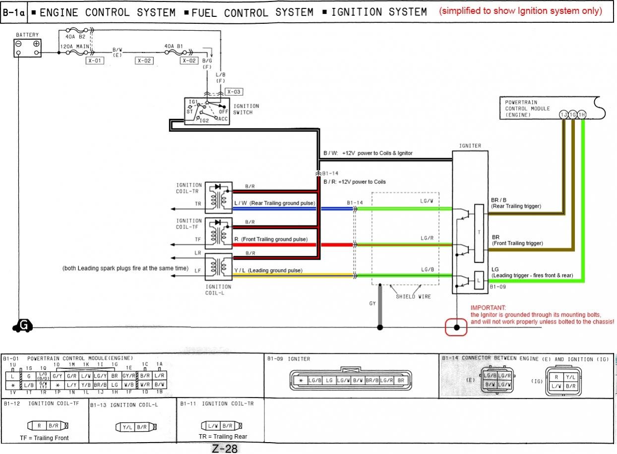
Following the diagram from the ECU to the Leading ignition coil, here's how it works:
Light Green:
The Light Green wire is the 0/5V trigger signal from the ECU. The voltage at this wire will be 0V for most of the time, with a very short 5V pulse when the ECU tells the ignitor to charge the coil. This pulse will be about 0.003 seconds, you won't be able to measure it using a multimeter in voltage mode. You may be able to measure it if your multimeter has a Frequency mode.
Light Breen / Black:
This is the wire that the ignitor uses when charging the ignition coil. The voltage at this wire will be 12V most of the time, with a very short 0V pulse when the ignitor charges the ignition coil. This pulse will be about 0.003 seconds, you won't be able to measure it using a multimeter in voltage mode. You may be able to measure it if your multimeter has a Frequency mode.
Yellow / Blue:
This is the same signal as the Light Green / Black wire, but the wire changes color in the Ignition harness near the coils. It wasn't very nice of Mazda to do that, changing wire colors makes things more difficult to follow.
Black / Red:
This is constant +12V power to the ignition coils. This wire should always be at least +12V when the ignition key is on. The Black/Red wire from each coil is connected to the Black/Red wire from all the other coils.
Here's how system works together:
1. The ECU decides it wants to fire the ignition coil. The coil doesn't fire instantly, it needs to be charged before it can fire. To do this, the ECU sends a 5V signal to the ignitor, telling it to start charging the coil. (LG wire between the ECU and ignitor)
2. When the ignitor receives the 5V signal from the ECU, it quickly switches a transistor ON, connecting one side of the ignition coil to ground. Assuming there is +12V power at the other side of the ignition coil (B/R wire), this causes current to flow through the ignition coil, charging it up and creating a magnetic field inside the ignition coil. (LG/B wire between the ignitor and leading coil)
3. When the ECU wants to actually fire the coil, it stops sending 5V to the ignitor, and sends 0V instead.
4. When the ignitor sees 0V from the ECU trigger wire, it quickly turns its transistor OFF, which stops charging the coil. (the LG/B wire will measure 12V again, since it is not being grounded by the ignitor)
5. When the ignitor stops charging the coil, the magnetic field inside the ignition coil collapses and this causes a high-voltage spark on the spark plug wires.
I originally wrote this because someone had damaged an ignition coil after installing an MSD amplifier and was trying to troubleshoot why things didn't work after trying to put the wiring back to stock. I took so long editing the diagram that I couldn't reply to the original thread... but hopefully this info will be interesting to someone else.
Last edited by scotty305; 07-31-11 at 04:16 PM.

The following 3 users liked this post by scotty305:


 04-14-14, 12:39 PM
#4
Cool read! This is one of those questions I would never think to ask unless I was having problems. You made it seem really simple which is great.
One question though, maybe grounds for a new thread but how does a unit like the HKS twin power tie in to all of this?
One question though, maybe grounds for a new thread but how does a unit like the HKS twin power tie in to all of this?
05-18-16, 10:42 AM
#5
Believe that my problem with the igniter is its not bolted to the chassis, but tucked. . As per the above attachment, it has to be.
Thats quite the ordeal and wish i saw this earlier.
Yay 2 year old thread.
Thats quite the ordeal and wish i saw this earlier.
Yay 2 year old thread.
05-18-16, 11:14 PM
#6
Moderator
iTrader: (3)
Join Date: Mar 2001
Location: https://www2.mazda.com/en/100th/
Posts: 30,802
Received 2,577 Likes
on
1,831 Posts
something like the b&M new volt goes into the coil power wire and can feed them a higher voltage.
basically if you have a given coil, its ignition power is a function of voltage and available time to charge it (its like injector duty). if you want to increase coil power you can increase the voltage, or charge it longer. or option 3 is to use it as a transformer, which is what CDI boxes do.
06-17-16, 05:44 PM
#7
just throwing the questions out there but what purpose does the ground serve on the <strike>newer</strike> older coil pack harnesses that actually connects to the coil packs AND do the coil packs themselves have any bearing on function as whether or not they are grounded. ex: if you found a way to get the coil packs to defy gravity and float, would the ignition system be negatively affected?
sorry to word it that way but i dont want there to be any misinterpretation as to what i am asking
sorry to word it that way but i dont want there to be any misinterpretation as to what i am asking
Last edited by cr-rex; 06-17-16 at 05:47 PM.
Trending Topics
06-17-16, 09:37 PM
#8
Original Gangster/Rotary!

iTrader: (213)
The newer harnesses integrate the ground into the wiring and don't have the tiny ring connector that bolts to down with the M4 nut.
A long while back I was troubleshooting ignition issues and found that swapping out a powder coated coil bracket for a bare metal one helped clear up a weak spark..... no actual proof that the coils 'need' to be grounded to the block though
A long while back I was troubleshooting ignition issues and found that swapping out a powder coated coil bracket for a bare metal one helped clear up a weak spark..... no actual proof that the coils 'need' to be grounded to the block though
06-18-16, 12:57 AM
#9
that is exactly what i wanted to hear. my coil relocation is on a custom bracket that has been "enameled" and then backed with a felt to protect the paint in the bay. a grounding nightmare. i havent been able to find any information as to whether or not the coil packs themselves need to be grounded other than it kind of being mentioned here
Proper RX-7 Grounding Procedures
but before i went out and found that factory cage thing for them and reinstalled in the stock location, i wanted to be sure. it would be odd to me since the only actual metal part on them is the little ring where the mount studs go. i believe the body is some sort of plastic/rubber. maybe theres more to it than i understand but i will try putting them back and will report the results....
thanks
06-19-16, 09:32 AM
#10
just to update for future reference, my coil relocation bracket was showing absolutely zero conductivity no matter where i probed it with the multimeter. i had red on the fuse box and i tried to get some kind of reading to the bracket and not even the hardware securing the bracket was giving me a reading. i put the coil packs back to its stock configuration and it yielded no change other than now being a good ground.
for anyone interested in the issue i am troubleshooting here is a link
https://www.rx7club.com/3rd-generati...h-5th-1101940/
for anyone interested in the issue i am troubleshooting here is a link
https://www.rx7club.com/3rd-generati...h-5th-1101940/


Thread
Thread Starter
Forum
Replies
Last Post
befarrer
Microtech
3
08-22-15 05:52 PM