When you click on links to various merchants on this site and make a purchase, this can result in this site earning a commission. Affiliate programs and affiliations include, but are not limited to, the eBay Partner Network.
Making this thread to track progress and ideas on my various electrical gremlins. Feel free to add any thoughts or advise if you think of something I should consider.
My 93's engine was fully rebuilt and upgraded. Many electrical issues remain for me to deal with. What I've found so far.
1. Turbo timer wasn't doing anything. Completely removed it for now.
2. The headlights pop up and do work. Pushing the stalk forward a bit causes the headlights to try to retract and turn off, but then pop back up and stay on. Either something is wrong with the stalk or there is a short somewhere.
3. The left turn signals operate normally. The right flash fast. The tail lights don't turn on at all. The dash lights don't turn on. Have checked fuses and bought one new TNS relay. Plan to replace all fuses just to rule that out.
4. A burned out spade in the ignition switch connector of the front harness is burned black. Bought a new ignition switch to eventually install once I know what caused this to happen. The burned out spade was originally connected to the turbo timer harness, which shows an equivalent burn on it. I plan to plug this directly into the ignition switch once I make sure things are ok electrically.
5. Sourcing a complete front harness. I think I might need to just replace the entire thing to rule out any issues. The PO did a real hack job on the stereo install too, so considering a redo of that harness.
6. Pulled out all bulbs. None are burned out. Plan to check continuity of all sockets to start. Reviewing the body electrical troubleshooting manual.
From the photos you sent, that turbo timer drew a lot of current!
Go through the wiring diagram manual systematically.
1. Verify that your wiring harnesses pass resistance checks between system elements.
2. The headlight and turn signal problems may be caused by the Body CPU. You can remove the circuit board from the CPU and inspect it for charring or burned up components. Since the turbo timer had a melted shell, then seriously look over the Body CPU for damage.
3. The right turn signal fast flash typically indicates a burned out bulb or poor conductivity between the bulb and socket. Since you said the bulbs are good then verify its socket. For instance, my right front turn signal was burned out but the bulb was good. I took the socket apart and cleaned up the corrosion that formed between the wire and socket. The turn signal came back to life and had no issues since.
4. Before you drop some serious cash on wire harnesses, inspect and document any problems first. The repair(s) may be simple. I would also recommend checking your speedometer circuit board for any potential problems with capacitor leakage. I have plenty of info about it on a few threads.
Best of luck to you and please keep the forum posted on your progress!
Yeah, get a new ignition switch module before you do anything else. A bad one will do all sorts of weird stuff. They're cheap, last I saw Rock Auto had them for a reasonable price and were in a Mazda part box.
Fast turn signals is either the flasher module in the CPU or a bad bulb. Possibly a bad tail light harness. The fast flashing is the flasher module telling you there is a burned out bulb.
Most of this stuff is probably pretty easy to fix. Just tackle things step by step.
What type of bulbs to you have in the light assemblies? Are they standard incandescent bulbs or LEDs? If any are LEDs then you would get a fast flash on the side that has it because the current draw is considerably less than a conventional bulb.
Go through the wiring diagram manual systematically.
1. Verify that your wiring harnesses pass resistance checks between system elements.
2. The headlight and turn signal problems may be caused by the Body CPU. You can remove the circuit board from the CPU and inspect it for charring or burned up components. Since the turbo timer had a melted shell, then seriously look over the Body CPU for damage.
3. The right turn signal fast flash typically indicates a burned out bulb or poor conductivity between the bulb and socket. Since you said the bulbs are good then verify its socket. For instance, my right front turn signal was burned out but the bulb was good. I took the socket apart and cleaned up the corrosion that formed between the wire and socket. The turn signal came back to life and had no issues since.
4. Before you drop some serious cash on wire harnesses, inspect and document any problems first. The repair(s) may be simple. I would also recommend checking your speedometer circuit board for any potential problems with capacitor leakage. I have plenty of info about it on a few threads.
Defly going to do all this. Not a short job so I need to make the time to do it. I'm going to check CPU2, might be the simple fix. My biggest concern right now is "finding" something wrong, fixing that, and then that going wrong again (for example, if CPU2 is a problem and I fix it for it, but another problem I didn't find/resolve damages it afterwards). I figure going through the wiring first is probably the safest initial step to confirm the connections aren't a problem. What do you think? I also thought about getting a JDM harness for cheap off eBay just to salvage the connectors to rebuild parts of mine.
Originally Posted by DaleClark
Yeah, get a new ignition switch module before you do anything else. A bad one will do all sorts of weird stuff. They're cheap, last I saw Rock Auto had them for a reasonable price and were in a Mazda part box.
Exactly! Ignition switch from Rock Auto is already in my cabinet waiting to be installed. I only want to make sure I don't install it before I resolve anything else that could cause the new one to have a problem or get damaged.
Originally Posted by TwinCharged RX7
Do yourself a favor and throw out the turbo timer. There is no need.
Done. Removed and I don't plan to put it back. It wasn't working anyway and everything is wired like crap from the PO, so I hope to resolve all of that over time. For example, my biggest pet peeve with car electronics is people who splice an aftermarket head unit into a car rather than use a harness when one is available. Drives me mad. If one isn't available I get it, but when it's a $10-20 part, it just irks me to no end.
Originally Posted by Gen2n3
What type of bulbs to you have in the light assemblies? Are they standard incandescent bulbs or LEDs?
So far I found all incandescents. No LEDs anywhere. I'll keep going through and make sure.
The battery was also relocated to the trunk of the car.
Thank you for the feedback. I'm glad to hear that you eliminated the turbo timer and verified that the bulbs are not LEDs. Here are my recommendations:
1. Disconnect the battery, remove it from the car, and place it on a battery tender (if you use one). I keep one on my FD all the time - that battery is 10+yrs old! Verify the wiring to and from the battery is sound, relocated in the trunk. Is the right gauge wire used? Does corrosion exist between connectors? Is the Ground wire connected properly - no breaks?
2. Pick the low hanging fruit! Replace the ignition switch. You already identified it as a problem and have the new part. Once replaced, check that problem off your list. Remove and inspect the Body CPU. First examine the flasher board for any damage then inspect the main board (the main board is the long one under the "surf board" panel). Damage may not be obvious therefore do not reinstall it into the car.
3. Perform resistance checks on the wire harnesses, refer to the wiring diagram manual Section X for more info. I would print off each applicable wiring diagram section, highlight the traces to test then check them off. This will certainly take time to complete but persevere. This procedure will remove all doubts in your mind that the harness is good to go. A break in the wiring may not be exclusively in the Front harness. It could be elsewhere - the Emissions harness, Instrument Panel harness, etc... Check the wiring from start to end point. Take note then continue until finished. Avoid going down the rabbit hole on the 1st problem - separate harnesses to find that specific fault. Note all the problems then see what they have in common.
4. Connectors can be sourced without purchasing a harness, JDM or USDM type. Again, save the expense on a new harness until you are certain that damage cannot be easily repaired. I have a thread about connector purchases.
5. Approx 90% of all electrical problems happen within 1" of a connector. Never discount the failure of a connector either!
Ask if you have more questions. Keep us posted on your progress!
I did two things recently. First, I pulled the front passenger blinker since I noticed it wasn't working at all. I found the shared ground connection to be totally bare, no insulation or heat shrink. The PO also did a hack job on the hot wires.
Second, I opened CPU2 and found what I believe to be at least one but possible two resistors needing replacement. They're R18 and R19 in the photo. The C2 capacitor also has some blackening on the left pad, but the cap itself doesn't look bad. I could replace it as a precaution. Sorry for the large image, I wanted to capture as much detail as possible.
R18 and R19 are actually fine. That black stuff you see is actually acid (electrolyte) from the capacitor C2 leaking out. Clean off the circuit board with isopropyl alcohol and an acid brush or tooth brush. Pay attention to the solder joints of R18 and R19. They may look tarnished after cleaning. The solder joints still provide a good electrical and mechanical bond so don't mess with them. I would recommend replacing C2. Afterwards, the board should be good to go unless it has other gremlins. What does the rest of the board look like?
Very good to hear! Well done on the visual inspection! You did a great job cleaning up the eyelets too. I presume you are no stranger to soldering components? What are the values of C2 and C3? Please remember to observe the polarity of electrolytic caps. The filled in half-moon on the circuit board denotes the negative lead.
Yep, luckily this has a lot more room than I normally solder. =)
Both 16V, C2 is 10uF and C3 is 220uF. Looks like I gotta wait for a DigiKey delivery to do this. I think these will do. Figure I'll purposely get the wider temp rating and 2000 hour lifetime caps.
Excellent! What other progress have you made with your wiring harnesses? While you are at it, now may be a good time to check your speedometer circuit board before the odometer blanks out. I met with 2 other members within 1 week who needed help in repairing them. BTW, I'm not trying to jinx you.
I replaced the caps and reinstalled the unit. Still fast flashing on the passenger side. I insistedi all the sockets and the bulbs work when I install them in the driver's side sockets. There's also a coolant leak I noticed, so another issue to deal with. I should really just get rid of the car, in 2+ years of ownership it's spent 2 in shops and driven a total of 40 miles. This was totally not worth it.
I understand your frustration with electrical problems. Especially when you inherit the sins from a previous owner. I encourage you to take the time to methodically take resistance measurements and you will be rewarded for fixing all the electrical problems.
Have you inspected the flasher CPU from the Body CPU? Remember, this is a separate card from the main board that you found bad capacitors. The flasher CPU controls the flash rate. However, since you still have one side that fast flashes, there may still be a problem with the wiring.
Please refresh my memory: when you test the turn signals, do you see the lights flash on the front AND back lenses? When the right side fast flashes, do you see both the front AND rear lights flash? Have you verified the turn signal sockets make a good connection and/or cleaned the corrosion from them? The front turn light assemblies typically get water intrusion than the rear and will corrode.
In an earlier post, you commented that the rear lights do not come on. What exactly do you mean by this? Do they not come on when you turn the combination switch (on the stalk) to Park or Headlight? If so, that is a function of the TNS circuit which flows through the Body CPU. After you soldered the new capacitors in place, did those lights come back on? BTW, TNS is an acronym for Tail, Number, and Side lights that references the lights when the combination switch is set to Park or Headlight.
If the front right turn signal does not flash then try this:
1. Remove the right side turn signal housing and unplug it.
2. Remove the left side turn signal housing and unplug it.
3. Connect the left side turn signal into the right side connector.
4. Test right turn signal for fast flash.
5. If no fast-flash happens with the left turn light housing plugged into the right side then inspect the right turn signal housing for proper connection.
I inspected the flasher, I didn't see anything. Maybe I'll pull it and give it another once over to be sure.
Right now, the passenger rear turn signal illuminates with fast flashing. The front passenger turn signal doesn't illuminate at all.
The running lights don't illuminate when the light switch is fully on. Headlights light up, but that's all. Dash lights don't light either.
This is what the PO did with the passenger front turn signal wiring. Maybe the splice job on the ground bypassing the connector is no good. The hot lines were also not soldered, just twisted and exposed with no insulation or heat shrink. I can solder and shrink those, and redo the ground.
I suspected the fast flash was the cause of a lens assembly out. I don't think you can swap lens assemblies because of the wire splicing. That must indicate a pin is broken/corroded inside either half of the connector. Are these stock lenses or aftermarket? If aftermarket, which one?
NOTE: It is obvious that the splice job to the right lens assembly was poor. The exposed wires could easily cause a short to chassis ground.
The proper thing to do is to replace the connector. This way you know the repair is permanent and it is done right. They can be sourced online. I have a thread that covers connectors for the RX-7 of all generations. Take a look here: Electrical Connectors
If you want to take some pictures of the flasher CPU and post then I could review it. However, I suspect the main culprit of your fast flash problem rests with that right front lens assembly. How does the left front lens wiring/connector look? Make sure you inspect the inside of the connector.
As for the dash lights, have you verified the fuses are good? It is a good idea to frequently check the fuse box for any blown fuses as you diagnose multiple electrical gremlins. This helps to avoid chasing your tail. Could you explain more about the dash light problem? Is it a backlight (gauge) illumination problem, warning light illumination problem, interior dome & map light problem, a combination of problems, or another issue? Refer to the Diagram C-1a & C-1b for the Instrument Cluster & Warning Lights and Diagram I-2 (as in capitol i) for the Illumination Lights.
Do the same with the parking lights, aka TNS lights. Check for blown fuses first. Then refer to Diagram E-3 (Pg Z-58) in the wiring diagram manual. I would even suggest that you inspect the wiring at the tail lights as the 2nd step (1st step is to verify fuses). If the front lens assemblies were hacked then you may see a similar problem in the rear. Did the PO install an aftermarket car alarm? Did you remove it? Again, by looking at Diagram E-3, the potential problems to cause no TNS lights are: TNS relay, Body CPU (CPU#2), and CPU#1. CPU#1 is physically on the back side of the fuse box. Do not forget the potential of broken/shorted wires in this system!
Unfortunately I get to work on this car 15-30 minutes at a time, and I find myself rushing to make any progress. This is what's happened the last three times, all due to rushing.
First, I reversed the battery wires one day. Sure enough, 120A main fuse exploded. Went to Autozone a week later, $3 spent and I have a main fuse. I got home, fitted it just to make sure I got the right one, pulled out the battery, hooked it up to my tender, and was done.
Then another week later, I hooked up the battery... notice I didn't say I finished bolting back the connections to the main fuse. After a loud spark, one of the connectors that go to the main fuse was spot welded to the intercooler piping. Disconnected the battery, hooked it up to my tender, and went to work on the connections for the main fuse. Which of course were burning hot to the touch, so I waited for them to cool down.
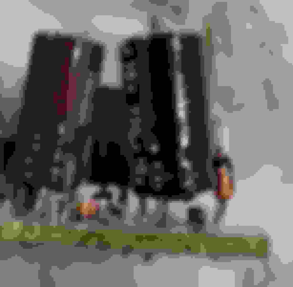
Then I realized, I don't even remember from weeks ago how the main fuse was connected. Here's a pic to explain.
The red arrow goes on the left side. The thing I can't remember is, the blue arrow connections. I see two eyelet connectors. But I don't remember which leg of the connector they belong on. I don't know if they were originally as I'm showing them here, that's how I happened to do it today and realized I'd rather not guess it and invite more risk.
The reason I'm focusing on this is because I need to start the car and see where this coolant leak is coming from. The whole engine was rebuilt and it drove 40 miles (from a body shop to my house) so I don't get why there'd be a giant pool of coolant on my garage slab. Before bothering with more of the electrical issues, I want to deal with that coolant leak and it seems to only happen when the car is running.
Sounds like this is a textbook example of haste makes waste. Patience is necessary when it comes to testing wires or connecting/disconnecting them. I would also encourage you to inspect the Body CPU (all boards inside) for additional damage that may result from cross-connecting your battery. How do I know? This happened to my Vert: Battery Reverse Polarity
Do those wires/eyelets at the Blue Arrow connect to chassis ground? What is underneath all that tape? What type of tape is that? Is your battery relocated to the trunk or storage bin? Is that Red Arrow pointing to a component that attaches to the intercooler piping? That piping should have no electrical connections nor serve as an electrical ground.
I would disconnect your battery first and then break out a DMM to read resistance of these wires to figure it out. Otherwise, you may wind up killing another battery, blowing another 120A fuse, and causing more damage to other electrical components. Lastly, draw a schematic of your battery connections and keep it with your manuals to prevent future cross-connections.
Make sure that you identify which cables connect to the Positive and Negative terminals of your battery. Using a DMM (Digital Multimeter) will help you. I get the impression that these 2 wires in your photo are not meant to connect to one another. Do you know what is under all that tape? It would be very important to identify the Negative cable and Positive cable of the original battery location then track them to the battery's new location in the trunk. These cables are typically thicker than the others because they must deliver higher amounts of current, especially to the starter and charging circuits.
Something weird I see. The fuse space above the main fuse is shown as unused on the cover. Why is there a fuse in that position on my car?
Prior to these issues, the car ran and drove so I don't think having a fuse there adversely affected anything. But what I'm trying to figure out is, why is it there in the first place?
I also noticed on inspection that it was blown anyway.
First, did you reconnect the battery properly? How did you solve that problem? The answer to your mysterious fuse rests with the PO. Was the PO a forum member? Maybe you could read some of his old posts to indicate what was done to the car? Can you inspect the fuse holder from below and trace back the wires? Do these wires look OEM? If the mysterious fuse was blown then there must be a reason for it. What size is the fuse? It could be for an upgraded fuel pump, stereo, or something else that would need high current. Additionally, did you fix the turn signal and headlight problems after the you found the sketch wiring and repaired the Body CPU? Lastly, did you replace the ignition switch?
Today was an interesting day. Last weekend, I was able to get the car started back up. Engine ran fine, and no damage from the battery mishap seems to have occurred. I also managed to identify the sources of the coolant leak and tightened up some fittings. Hopefully that's all it needed.
I also replaced the ignition switch with the one I picked up from Rock Auto, just cuz why not.
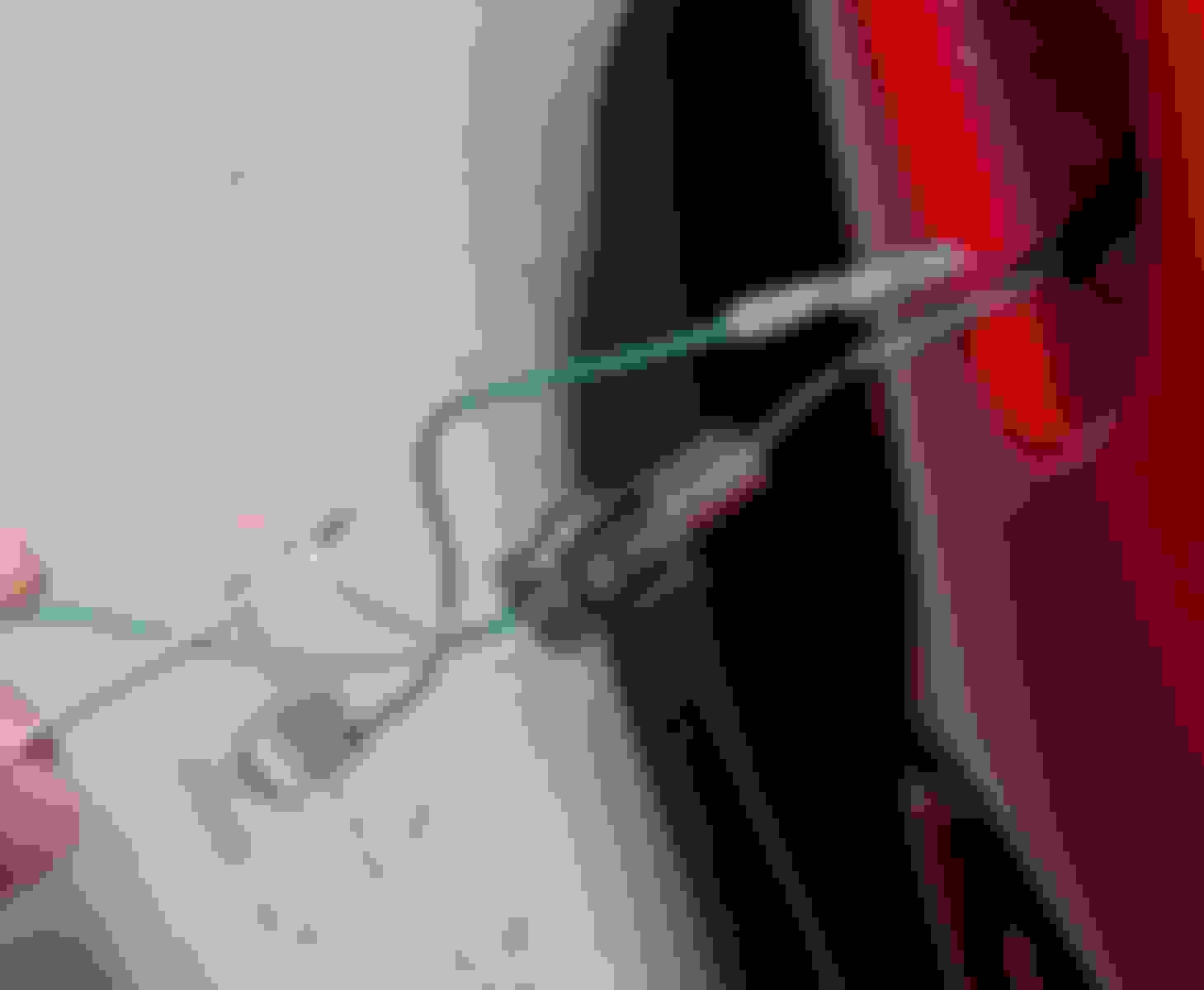
On to today's electrical investigation. First, I opened up that that crimp connector that was on the passenger side headlight just to see what was in there. This is what I found.
This was just two wires twisted together with some random third wire section thrown in... just cuz? Who knows. Thanks PO!
So, I did some testing with a test light and I was able to make bulbs light up but still with fast flashing. I then went to the Body CPU to pull it thinking I need to open it up again, and I took a closer look at it... and noticed this.
Two wires going to the connector were in need of repair. One was completely cut through, the other was only connected by two strands of the wire.
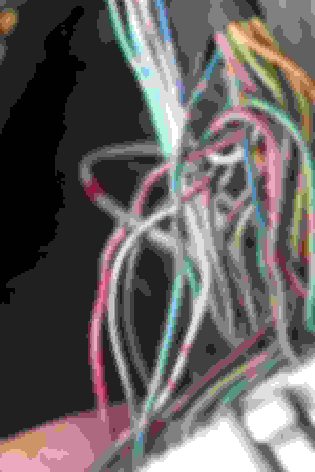
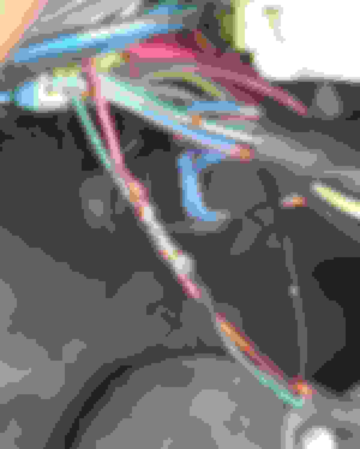
I broke out the soldering iron and head shrink, went to work, and plugged it all back in. Still fast flashing on the passenger side, but those wires needed to be addressed anyway, so I felt a lil accomplished. Until I noticed something odd. Whenever I see black electrical tape where it probably doesn't belong, it always makes me pause. This is what I saw for the two wires going from the light stalk to a connecter under the steering column when I removed the tape.
Now I know they did some weird things on this car, but I doubt that was factory spec. I unfurled this tangled mess of wire, and I found that the two wires coming from the light stalk were bare and touching while some random bundle of stranded wire was just wrapped around them. You can see me holding up that bundle in the bottom left of the pic.
This was... just disturbing. Even more confusing, my headlights were not popping up and turning on reliably already. Once I undid this and separated the wires as you see above, the headlights refused to work at all. I rubbed those two wires together, and it would make the lights then work. I found this odd. If those two wires are in fact supposed to touch, why wouldn't they just, from the factory, jumper them at their ends and use a single wire. This seems like an unreasonably strange way to do this, if in fact it's supposed to be like that. I'm hoping someone can tell me from their stock working lights if in fact those two wires should be bare and touching along their length before they go into the blue connector. I'm also going to inspect this further. For now, moving on.
I finally got fed up with this flashing issue... I decided, with some encouragement from the wife, to just cut off the male end of the 3 pin connector feeding the turn signal on the passenger side. At this point, I really felt something could be wrong with the connector itself. I moved the whole light section with the female connector to the driver's side, and it worked fine. So, I grabbed the wire cutters, snipped it, did some quick twists with the turn signal socket and the test light... and there was no fast flashing.
So, the source of the passenger side fast flashing was this connector alone.
I want to replace this connector. Hopefully I can find this connector. If not, I'm going to replace it with any 3 pin connector male/female pair I can get my hands on.
I still need to figure out the gauge cluster lighting, but I feel like this was a good breakthrough. At least I can resolve the fast flashing now. Some progress is better than no progress. Tomorrow I'll try to think about the gauge cluster. It's really the only thing preventing me from driving now since I can resolve the fast flashing.
 12-27-17, 10:10 AM