13b-rew CAD/technical drawings

 05-09-15, 04:22 PM
#27
Rotary Enthusiast
Thread Starter
I do not think there are any real dwg's out there but i am more than willing to share any of my files if you are interested.
Been really busy with school, trying to get back into modeling this engine now.

 01-09-17, 01:57 PM
#29
Rotary Enthusiast

Hi Guy's I just stumbled across this thread and must say I am very impressed with he CAD work on show. I also work in design. mainly for composite tooling so I know exactly what goes into to as I have done a number of parts for my own cars over the years!
I was wondering slightly cheekily if anyone would be willing to share a CAD model of the E-shaft for a 13B engine? I am toying with something in my head but need something to pla with and short of cutting one to pieces a CAD model would be ideal. I would also be interested in housing, irons and rotors if my thought looks like it might work. Just to get things spacially right. What is the deal with the 4 rotor design/build I must find that thread! PM me if you prefer.
Thank you
Lee
01-11-17, 07:21 PM
#30
Rotary Enthusiast
Thread Starter
Hi Lee,
I am more than happy to share all the models I have created. Ill throw out the disclaimer that I have told everyone else ive shared with. I made these parts as close as I could using calipers and other tools but there are undoubtedly some errors so dont expect them to be close enough to send to a shop for machining.
That being said, shoot me a PM and I can share all files with you.
Matt
The following users liked this post:
Nimboy26 (01-05-21)
01-16-17, 11:01 AM
#32
Rotary Enthusiast
Thread Starter
01-18-17, 01:03 AM
#34
I'm trying to build up enough business to get a FaroArm, so I can do stuff like this guy's doing:
The Engineered 1UZ V8 Datsun 620 Build - Project Datto - Ratsun Forums
There's more on his instagram @3dmagicmike
The Engineered 1UZ V8 Datsun 620 Build - Project Datto - Ratsun Forums
There's more on his instagram @3dmagicmike
Last edited by MaczPayne; 01-18-17 at 01:06 AM.
01-19-17, 12:20 PM
#37
Rotary Enthusiast
Thread Starter
I'm trying to build up enough business to get a FaroArm, so I can do stuff like this guy's doing:
The Engineered 1UZ V8 Datsun 620 Build - Project Datto - Ratsun Forums
There's more on his instagram @3dmagicmike
The Engineered 1UZ V8 Datsun 620 Build - Project Datto - Ratsun Forums
There's more on his instagram @3dmagicmike
03-10-18, 08:35 PM
#40
Rotary Enthusiast
Thread Starter
I'm trying to build up enough business to get a FaroArm, so I can do stuff like this guy's doing:
The Engineered 1UZ V8 Datsun 620 Build - Project Datto - Ratsun Forums
There's more on his instagram @3dmagicmike
The Engineered 1UZ V8 Datsun 620 Build - Project Datto - Ratsun Forums
There's more on his instagram @3dmagicmike
Good news everyone. I now work at a company that has a FARO arm. Granted, I do not have the experience or skills that 3dmagicmike does but its a start!
This project hit a brick wall when I finished the "easy" parts and got to parts like the front iron, front cover, water pump etc. I am not sure how long it will take me to make solid models but I am compiling a collection of point clouds of all the engine parts. I will FARO scan the parts I have already modeled as well as other parts. The old parts can be tweaked or remodeled using the scans.
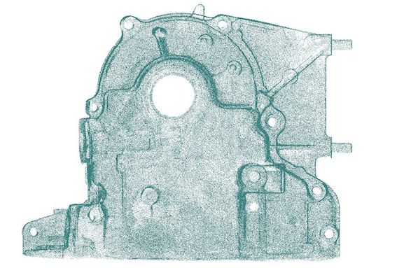
P.S. If anyone has any advise or experience reverse engineering from a point cloud I would love to hear it. The local FARO arm rep things 3dmagicmike is using geomagic software, not sure how much that helps in generating solid models. As far as I know it is still a very manual process and the points are basically for reference only.
Matt
04-21-18, 09:04 PM
#44
Rotary Enthusiast
Thread Starter
I have all the files saved to a google drive. If anyone is interested shoot me a PM. If anyone else is willing to generate point clouds of parts I have yet to scan that would be a HUGE help. Granted we will have to model them after that but its a great starting point!
Matt
Matt
11-28-19, 02:08 AM
#46
Can Post Only in New Member Section

Join Date: Nov 2019
Location: Melbourne
Posts: 1
Likes: 0
Received 0 Likes
on
0 Posts
Awesome thread guys, I have access to an SLM at work (basically a metal printing laser), I regularly prototype in Ti64, Al variants, some Cobalt Chromium and regular steels.
I have always wanted to print then machine to tolerance some Ti housings and rotors, given the mechanical properties I like the potential; at first glance I have concerns around thermal cycling and the apex seals but nothing that can�t be simulated and run with some CFD.
Anyway - my question, how accurate are these drawings? Has anyone machined, tolerances, results?
C
