When you click on links to various merchants on this site and make a purchase, this can result in this site earning a commission. Affiliate programs and affiliations include, but are not limited to, the eBay Partner Network.
So a friend of mine bought a pair of used carshop glow tails (non sequential ones) that are heavily used and definitely need some polishing as they look faded. However, the previous owner had just cut all the wires coming from them. Could be replicas for all I know.
We tried to install them and we actually wired them the way stock tails are wired. So there are three things wrong with the wiring.
1) When you turn the lights on, the whole cluster doesn't come on. You have to push the brake in order for the remainning LEDs on the sides to come on so that the actual shape appears. We tried wiring the brake lights to light the whole cluster but everytime the brake pedal was pushed it was like turning on low beams (headlights and dash would light up too lol).
2) Tail lights light up as soon as the ignition comes on, without turning on low beams.
It is supposed to be so that the whole LED cluster lights up when on low and main beam and shine brighter when the brake pedal is pushed.
How can we do that and correct the 2nd issue too?
Last edited by Andreas Avgeris; 08-14-18 at 08:35 AM.
Seems like you also need a "chasing module" which comes with the lights. That appears to be your issue. See around 2:47 of the install video. FYI - a quick search turned this up so the internet is your friend:
Thank you for your reply. Yes I've seen the video but I think the "chasing" module is only needed when the tails are actually the chasing ones. These are not. The hazards work perfectly as they should. The problem is on the brake lights. We know which wire runs what as we tested it after removing the stock tails. But it seems in order to work as Carshop glow intended it to it needs something more.
Then I would suggest using a 12 volt source - your battery or wiring up a 12-volt inverter like I do - to test each wire. You should be able to chase down which wire runs which function on the lights and go from there.
Using a 12 volt source and doing what? I know what all stock wires do because I installed the tails as if the wiring should be stock. Or do you mean I should test what each wire from the tail lights cluster does using the 12 volt source?
My friend already emailed carshop glow although I doubt he'll get an answer cause he didn't buy from them.
Yes, to the second part of your statement - test each Carshop Glow wire to determine what each does. You need to determine what wire runs the parking lights, the brake lights, and the turn signal functions. Once you know this, wire to the appropriate OEM wire. Out of curiosity, how many wires do you have coming out of the back of the CarShop Glow units?
The OEM taillight assembly is pretty simple when it comes to wiring. There is a parking light trigger wire that activates when you turn the light stalk switch one position. This sends power to the two inner 1157 light bulbs, giving you the less intensity parking lights. When you press on the brakes, a separate wire triggers the higher light intensity portion of the 1157 bulbs for your brake lights. A third wire triggers the outer, 1156 bulbs so your turn signals activate.
You need to find out what the wires coming out of the Carshop Glow lights do, and then match them to the OEM outputs. For this to work, there needs to be at least 3 wires coming out of the CarShop Glow lights, one for each of the above listed functions. If there are less than 3 wires from the CarShop Glow lights, I don't see how it is possible for your parking lights, brakes, and turn signals to all function without some intermediate control box, like the "chaser" one shown in the video. I asked the question about the wiring as I thought you'd have more than 3 wires and would need to figure out how to combine them to make everything work. Let me know what you find and maybe post up a pic or the wiring?
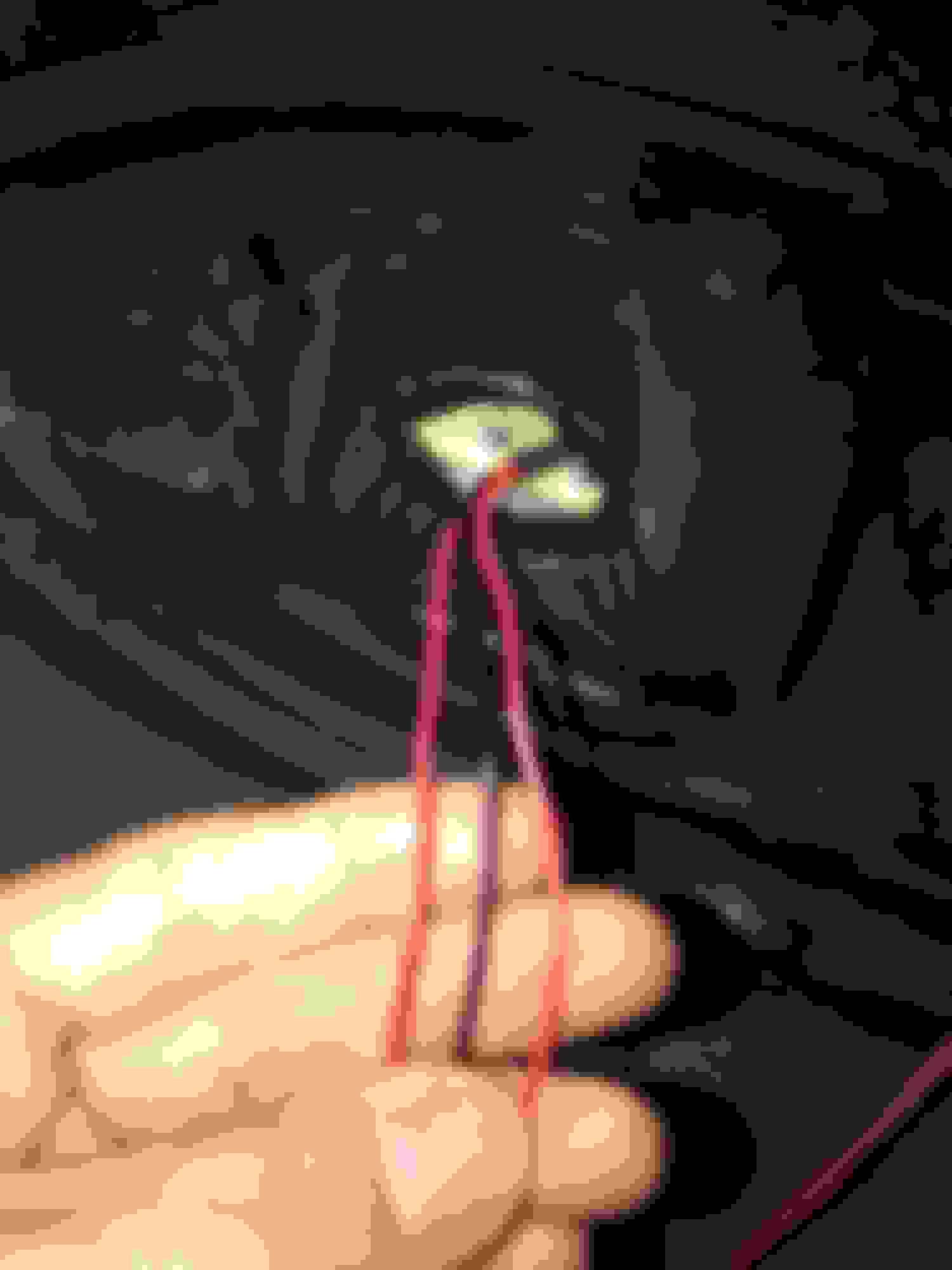
Okay, now unwrap the electrical tape from them to expose how they are connected together and to see the colors of the wires. I'd guess the two inner sockets (parking and brake lights) will be wired together but we need to confirm that. Not a big deal either way but that is what I did with my LED conversion (not Carshop Glow) as it is easier than wiring up each one separately. For the outer socket (turn signal), we need to isolate which wires are running into that socket so you can then wire them up to your stock wires.
So, unwrap everything and post up pics of what you see.
Wow, that is a bit of a mess. Black should be power and green a ground, with the one of other two wires (they should be striped) feeding your brakes and the other, your turn signal. I can't remember which does each function, but maybe someone can chime in here. You can test all of this though so no worries.
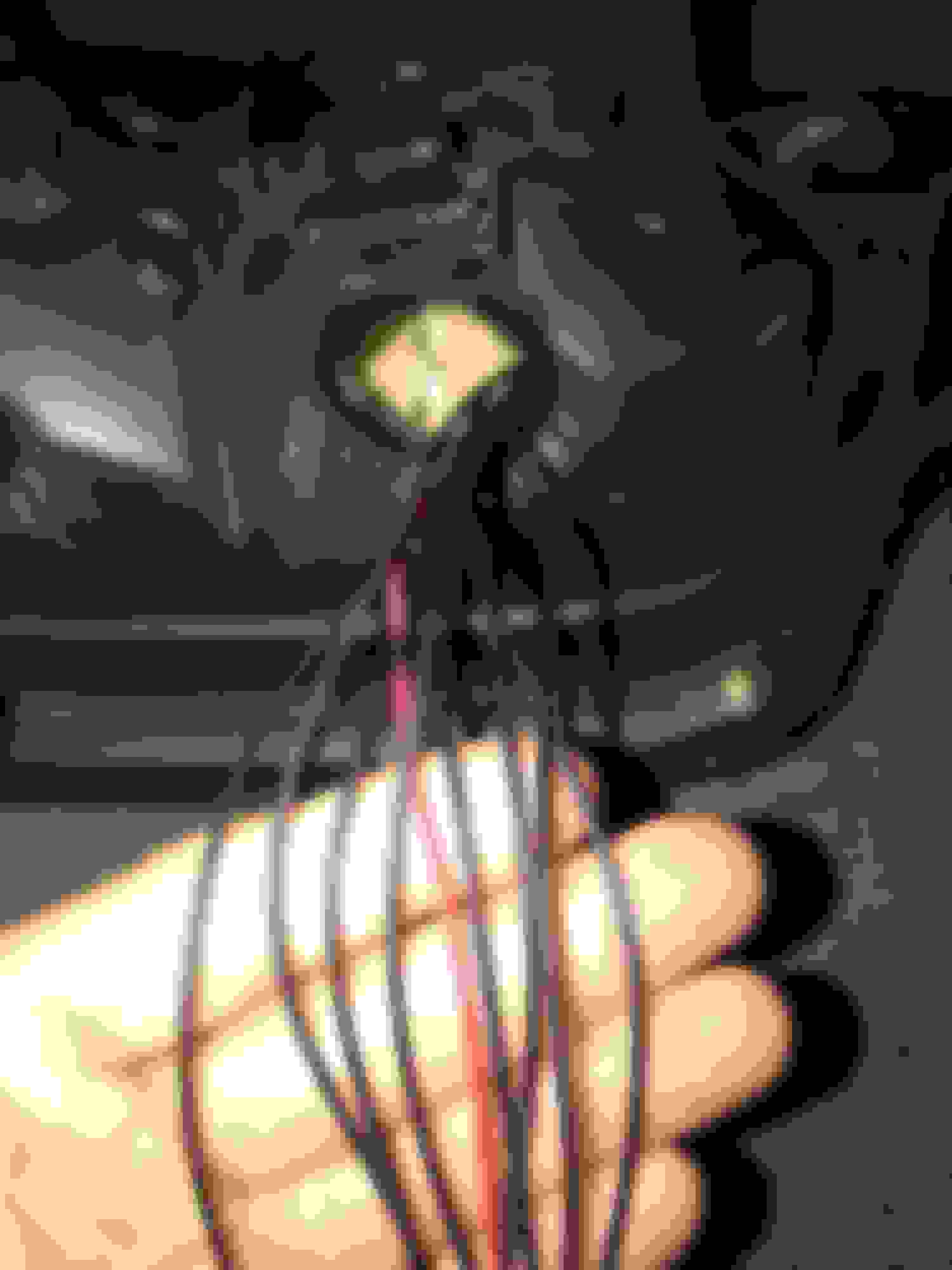
On the CSG wiring, you have a black/power wire running to the inner right (in the pic) socket and a black wire running into the outer left socket. It then looks like both are connected together (is this they way they came or did you connect these two together?) and then run into the OEM black/power wiring. I would have expected to see something else, namely the inner two right sockets wired together, but that is not the case. The inner socket only has one wire running into it, with the outer left having three CSG wires. This is definitely not stock.
So, I think the best way to proceed is to disconnect the CSG wiring from the stock wiring and then to test each CSG wire to see what function it turns on. Once you know this, you can label the wire so you know how to wire it up to the stock unit wiring. On the stock wiring, when you turn on the parking lights, a wire (the black OEM one I think) supplies power for the parking lights. We need to see which of the CSG wires performs the same function. Likewise, we then need to see which CSG wire is used to increase the lights for your brakes. I think on the CSG lights, they simply turn on more lights for the brakes versus increasing the intensity of some of them, but regardless, the goal is to find which one of the CSG wires turn on the brake lights. Finally, identify which of the CSG wires is used for the CSG turn signals.
So, I would proceed by disconnecting the CSG wiring and then use the car battery to provide power to each of the CSG wires to see what is turned on for that wire. Connect a black test wire to your battery + and a green one for ground - and then connect the ground to the green CSG wire - I am color blind but assume one of them is green. Once you have the ground connected to the green CSG wire, then use the black test wire from the battery to test each wire to see what lights up on the taillight.
When this is done, we will know what wire powers what and we can then proceed to properly connect the CSG wires to the stock OEM wiring. You can test what each OEM wire does by using a voltmeter to see when each wire is powered. If I am correct, black will see 12 volts when you turn on the parking lights. One of the other OEM wires will see 12 volts when you press the brakes, and the final wire (I am leaving green out as it is a ground) will activate 12 volts on and off when you turn on the turn signal. So, with this info, you can wire up everything correctly.
Yes I wish I could buy David a beer! So as we were messing around with the tails my neighbor who is an electrician engineer came to help and he brought his tools and everything. We rewired everything neatly and realized that the way they're wired inside the LED cluster there was no way for them to work as they should without the use of resistors because now if the brake is pressed it makes zero to a little difference so resistors will help emit less light when not braking. We're buying them tomorrow and installing. Big thanks to everyone who replied! Would love a 99 LED design too. Thanks guys!
Too funny. I live in the US beer capital (Asheville NC) so come on over and I will buy you a beer.
Following up on what you've posted, I went back to the CSG install video I posted and you are correct, the CSG lights use the same leds for both parking and braking. So, your electrical engineer neighbor is right, you will need to use a resister on the parking light wires to reduce the voltage for the parking lights. Then, when you press the brakes, the power supply from the non-resister wire will make the brake lights brighter. I also assume you then were able to locate which CSG wire activates your turn signals?
Regarding an LED 99 spec look, I posted up a DIY on how to do this a few years back. Here is the link:
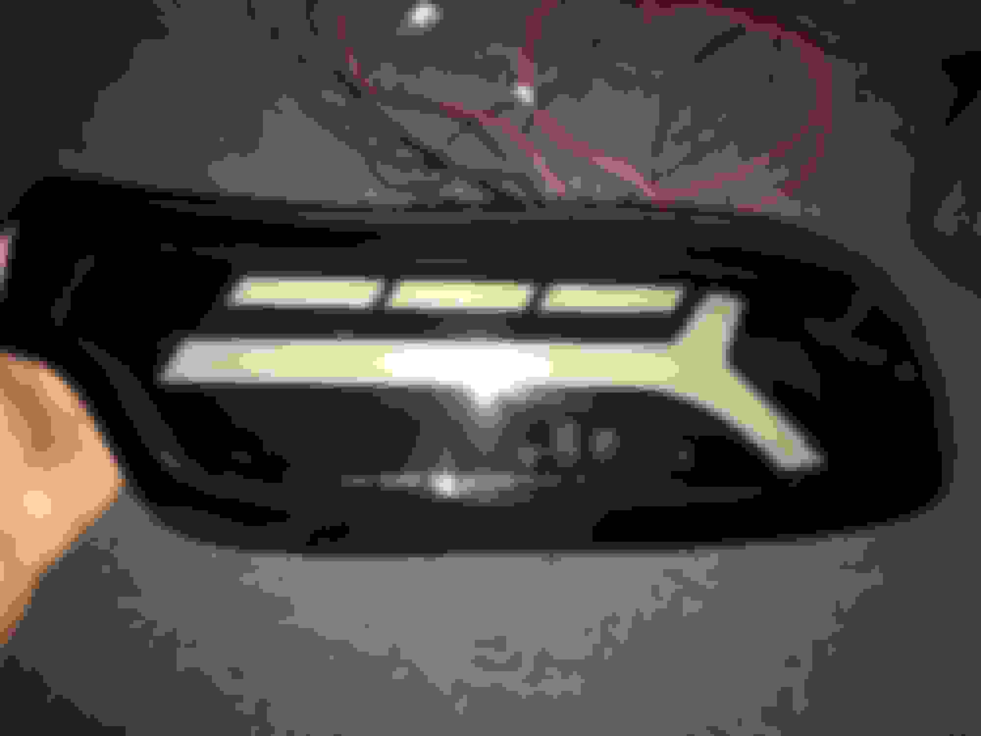
Here is a pic of the look - note I have the Pettit flares installed on the back end of the car so I went with 3 rings instead of the normal 99 spec 2 rings:
You can see I also converted the center brake light to a continuous LED look:
And then, for more LED fun, I retrofitted my front turn signals to all LED. When you use the turn signal, the white LED rings turn off and the amber turn signal comes on.
Yeah guys I got it all sorted thanks to your help and my neighbor's haha! I could never have done it alone that's for sure.
Dave I just saw what you did with the 99s... Now I want a set. Anyone selling? Cause I'm so useless with these things, especially electronics to follow the DIY and do it myself.
Glad it all worked out for you. You can contact turboIIrotary on this forum about LED taillights. He does some nice work. As for 99 spec turn signals, I don't know of anyone that does turn signals like mine, but CSG makes LED turn signals you might like: https://finalformusa.com/product-cat...car-shop-glow/
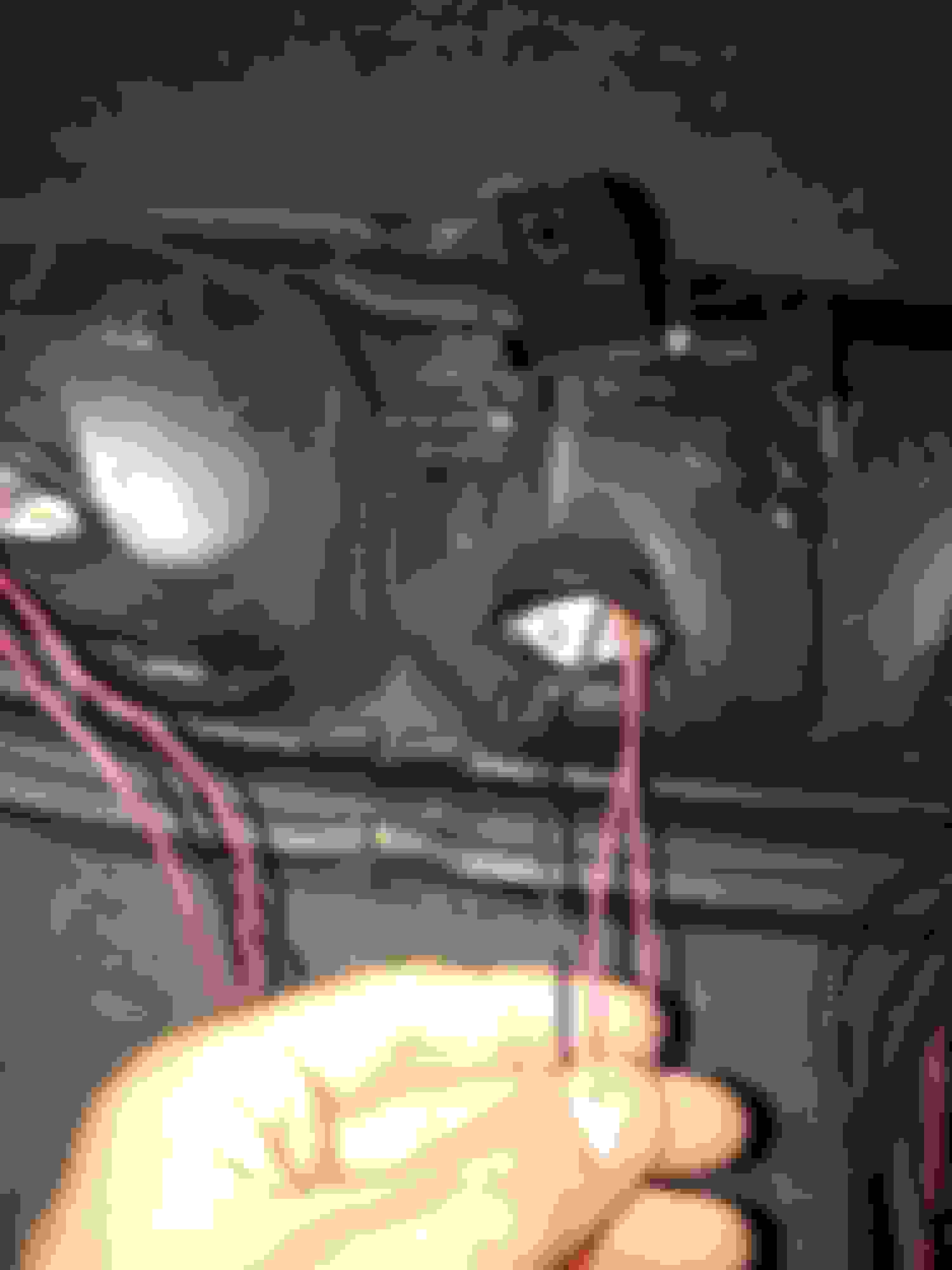
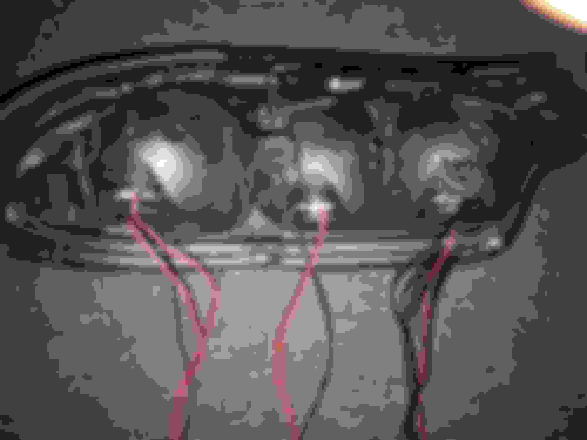
Holy crap, Batman, that's a lot of wires! No doubt you'd need a custom flasher/sequencer to get all of that to work. Do you know the brand of lights these are and if so, could you contact the maker directly? That's always the best route as you'd get the exact flasher/sequencer you'd need to make this work.
Looks like to me, the red wires are power wires and the black wires are grounds. I would assume the bunch of 8 black wires on the inside are for sequencing options. if it were me, I'd test each wire by connecting to a 12 volt source, like your battery. Our, as I do, I repurposed an old 120V to 12V volt adapter (plugs into the wall and converts the power to 12 volts) to use to test my LED projects. I'd hook up one red wire and then one black wire at a time and see which lights are activated. So, for example, I'd hook up the middle socket read wire to power and then the black wire to ground and note which lights come on. I'd then do the same for the left socket wire, hooking up on red and then one black. The question here is which black goes to which read but you can play around with the combo to figure this out. For the four wires on the left socket, I would then connect BOTH reds and blacks to see what happens when you do this. As for the mess of wires on the right, I'd hook up the red power wire and then test each of the 8 black wires to see what is the result. The problem here is trying to test combos of all 8 black wires. There are just too many combos to really do this.
If your goal is to use the lights without crazy sequencing, or the way the normal OEM lights work, I don't think this will be difficult. You just need to figure out which wires activate the parking lights, the brake lights, and then, the turn signals. So, you most likely won't need to use a bunch of the black wires that would normally be used for elaborate sequencing options. If you want full functionality, that is best solved by contacting the maker to acquire the flasher/sequencing box. Or, you could make a sequencer circuit but that is beyond my capability.
So, in any event, the first steps are to 1) contact the maker for a sequencer and instructions, or 2) start testing the wires.
 08-14-18, 08:32 AM


 Look forward to an update.