S5 TII vacuum diagram?

 05-17-09, 10:41 PM
#7
I'll copy this almost verbatim from another thread I have posted in:
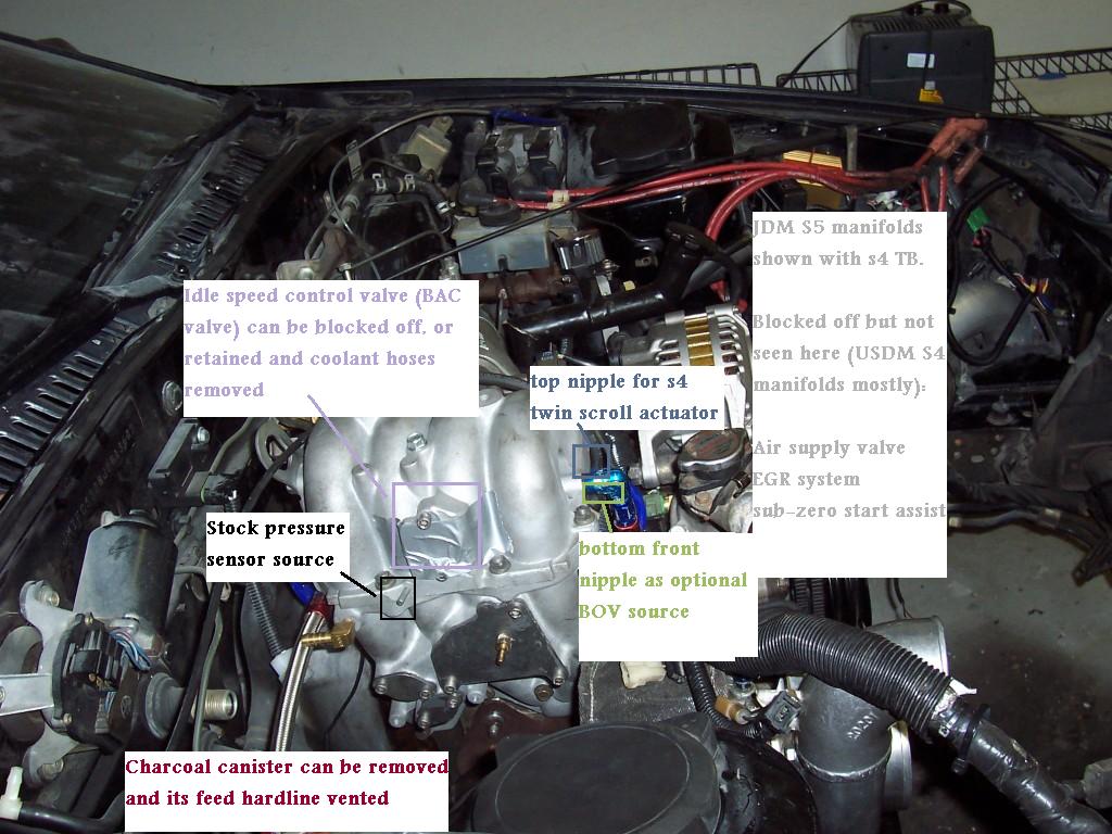
"A couple notes on these pics. First of all, they're really...busy. There's a lot of colors and labels going on, but it is a vacuum routing diagram. I haven't been on stock turbo in a while, and these pics were actually taken a couple weeks ago as I was doing vacuum routing for my new motor on the stand. The motor pictured here has JDM s5 manifolds with an s4 OMP and TB. It is running a Power FC, hence the stock engine harness.
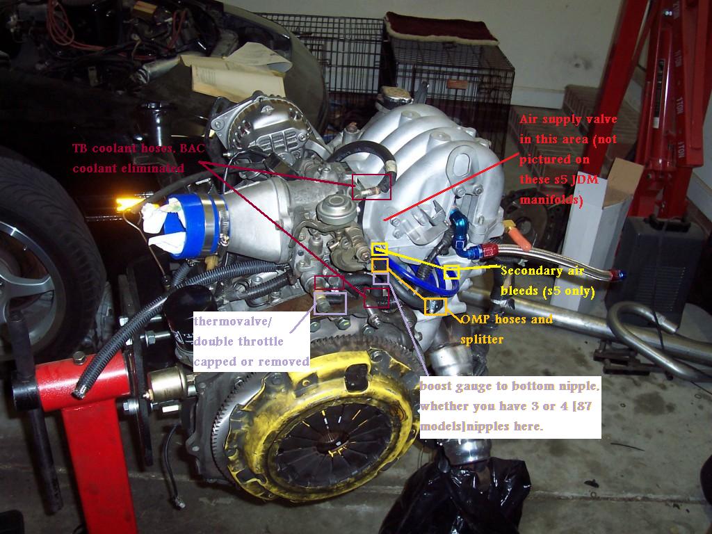
The cold idle system (thermowax and associated stuff) was retained here. The BAC valve was in the process of being reinstalled. My bias here is that after having removed the idle control systems like everybody else, I got really sick of the car stalling more easily and running like crap every time I started it in the morning. So I put them back on in simplified form. You can keep them if you want to, it's up to you. I have shown here how to route the coolant hose for the thermowax system while removing all the other coolant hoses, which are in fact unnecessary. I have not removed the double throttle system completely, merely capped off its vacuum nipples.
The secondary butterflys are still there, but they are not held closed while the engine is cold. You can do what you want with that system, pull it off if you feel like it. I had no problem putting 386 to the wheels with a bone stock TB so I don't think it affects power noticeably. After I put a stock TB back on (double throttle system fully hooked up) I personally noticed zero difference in throttle response once the engine was warm, but others do not share that opinion.
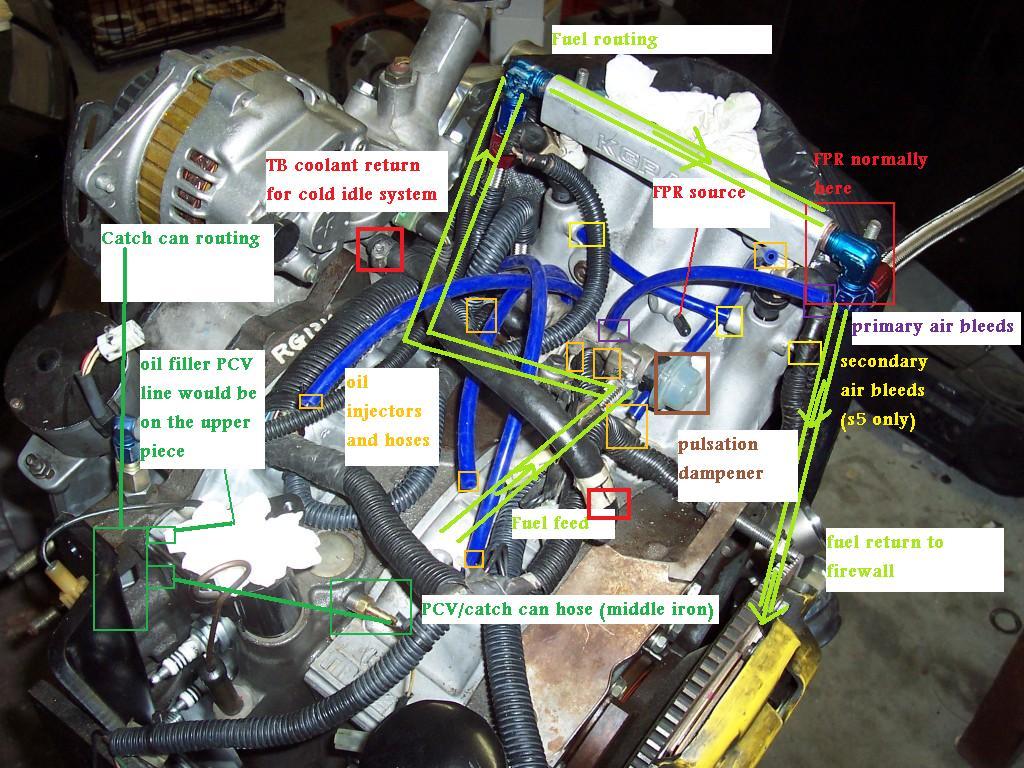
On to the pics. Note that these JDM s5 manifolds do not need blockoff plates for the air supply valve, EGR, or sub-zero start assist. The fuel routing diagram was done such that it would not block other stuff in the diagram. It goes Fuel filter --> primary rail through the pulsation dampener --> secondary rail --> exit to fuel return line, through the FPR"
The fuel lines are backwards I believe on an actual JDM S5. I have an s4 with JDM s5 manifolds, so that is not an issue for me. I have my primary air bleeds hooked to the middle nipple on the front of the UIM [not fully pictured] because the FSM seems to indicate that it is a fresh air source before the throttle plates. The brake booster source is on the rear secondary LIM runner. I think there is a barbed hardline on this from the factory to which you connect a hose. I tapped that with an NPT tap and installed a 90 degree 3/8 barb fitting. Then I took the brake booster hardline on the firewall and unbolted the last piece of it to give a better angle for the brake booster hose.
"A couple notes on these pics. First of all, they're really...busy. There's a lot of colors and labels going on, but it is a vacuum routing diagram. I haven't been on stock turbo in a while, and these pics were actually taken a couple weeks ago as I was doing vacuum routing for my new motor on the stand. The motor pictured here has JDM s5 manifolds with an s4 OMP and TB. It is running a Power FC, hence the stock engine harness.
The cold idle system (thermowax and associated stuff) was retained here. The BAC valve was in the process of being reinstalled. My bias here is that after having removed the idle control systems like everybody else, I got really sick of the car stalling more easily and running like crap every time I started it in the morning. So I put them back on in simplified form. You can keep them if you want to, it's up to you. I have shown here how to route the coolant hose for the thermowax system while removing all the other coolant hoses, which are in fact unnecessary. I have not removed the double throttle system completely, merely capped off its vacuum nipples.
The secondary butterflys are still there, but they are not held closed while the engine is cold. You can do what you want with that system, pull it off if you feel like it. I had no problem putting 386 to the wheels with a bone stock TB so I don't think it affects power noticeably. After I put a stock TB back on (double throttle system fully hooked up) I personally noticed zero difference in throttle response once the engine was warm, but others do not share that opinion.
On to the pics. Note that these JDM s5 manifolds do not need blockoff plates for the air supply valve, EGR, or sub-zero start assist. The fuel routing diagram was done such that it would not block other stuff in the diagram. It goes Fuel filter --> primary rail through the pulsation dampener --> secondary rail --> exit to fuel return line, through the FPR"
The fuel lines are backwards I believe on an actual JDM S5. I have an s4 with JDM s5 manifolds, so that is not an issue for me. I have my primary air bleeds hooked to the middle nipple on the front of the UIM [not fully pictured] because the FSM seems to indicate that it is a fresh air source before the throttle plates. The brake booster source is on the rear secondary LIM runner. I think there is a barbed hardline on this from the factory to which you connect a hose. I tapped that with an NPT tap and installed a 90 degree 3/8 barb fitting. Then I took the brake booster hardline on the firewall and unbolted the last piece of it to give a better angle for the brake booster hose.
The following users liked this post:
mr_vaughn (02-02-21)
Trending Topics
05-29-09, 06:46 AM
#10
Junior Member

Join Date: Aug 2007
Location: north dakota
Posts: 30
Likes: 0
Received 0 Likes
on
0 Posts
On the firewall side of my stock s5 upper intake manifold i have 4 connection points. from top going to the bottom what connects to them? correct me if i'm wrong but the factory diagram shows the top one going to the middle of the lower intake manifold, next one down goes to the round 4 plug gang block to the oil injectors, the third goes to the bottom of the lower intake between the two oil injectors (can i cap this one on both ends if i'm removing the oil injectors) and i have no where the hell the lower one goes to?
I'm doing the emissions removal. Getting rid of the air control valve, oil injection system the whole rats nest of vacuum lines, stock boost solenoid, relief solenoid, switch solenoid, leaving in the prc solenoid that controls the fuel pressure regulator, purge control valve stays. along with the lines to the charcoal canister.
Anyone that knows the correct routing of these 4 connections please help. I've tried to figure this out on my own using the factory manual and its just not making sense. Its currently the only thing i have left to figure out before i can finish and i plan on posting a detailed how to with pictures and easy to follow color coded diagrams of where everything should go for fellow rotary lovers that follow in our path.
05-29-09, 07:34 AM
#11
leaving in the prc solenoid that controls the fuel pressure regulator
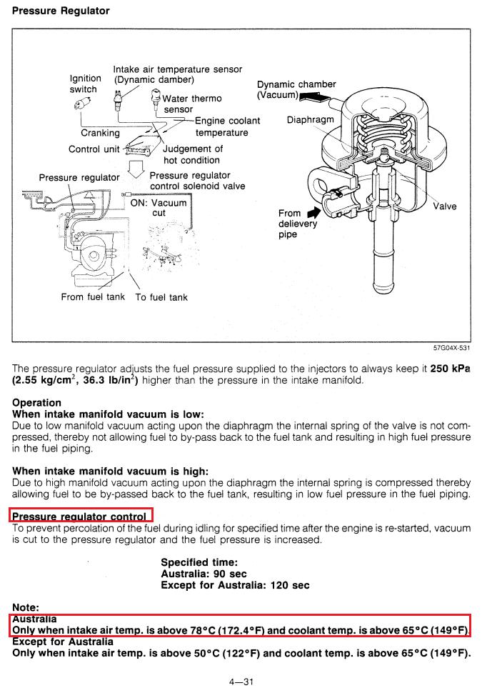
The problem with the PRC solenoid is that it only comes on at a very, very high air temperature. In all the logging I have done of the IAT sensor on my Power FC, I have never seen it get over about 72 C during a hot start. And that's only on a 100 degree day. So IMO it basically does nothing because it never engages. I'd just get rid of it if I were you.
07-16-20, 02:11 PM
#14
Senior Member
On the firewall side of my stock s5 upper intake manifold i have 4 connection points. from top going to the bottom what connects to them? correct me if i'm wrong but the factory diagram shows the top one going to the middle of the lower intake manifold, next one down goes to the round 4 plug gang block to the oil injectors, the third goes to the bottom of the lower intake between the two oil injectors (can i cap this one on both ends if i'm removing the oil injectors) and i have no where the hell the lower one goes to?
I'm doing the emissions removal. Getting rid of the air control valve, oil injection system the whole rats nest of vacuum lines, stock boost solenoid, relief solenoid, switch solenoid, leaving in the prc solenoid that controls the fuel pressure regulator, purge control valve stays. along with the lines to the charcoal canister.
Anyone that knows the correct routing of these 4 connections please help. I've tried to figure this out on my own using the factory manual and its just not making sense. Its currently the only thing i have left to figure out before i can finish and i plan on posting a detailed how to with pictures and easy to follow color coded diagrams of where everything should go for fellow rotary lovers that follow in our path.
I'm doing the emissions removal. Getting rid of the air control valve, oil injection system the whole rats nest of vacuum lines, stock boost solenoid, relief solenoid, switch solenoid, leaving in the prc solenoid that controls the fuel pressure regulator, purge control valve stays. along with the lines to the charcoal canister.
Anyone that knows the correct routing of these 4 connections please help. I've tried to figure this out on my own using the factory manual and its just not making sense. Its currently the only thing i have left to figure out before i can finish and i plan on posting a detailed how to with pictures and easy to follow color coded diagrams of where everything should go for fellow rotary lovers that follow in our path.


Thread
Thread Starter
Forum
Replies
Last Post
jimmydanny
2nd Generation Specific (1986-1992)
0
01-10-12 01:45 AM
CrypticApathy
2nd Generation Specific (1986-1992)
1
04-24-06 04:18 PM