
DFIS w/ Transistor Trick- Veteran Assistance Requested


Thread Starter
Joined: Jun 2005
Posts: 1,420
Likes: 4
From: clearwater, florida
DFIS w/ Transistor Trick- Veteran Assistance Requested
I carried this out 2 weeks ago, per THIS write up
https://www.rx7club.com/1st-gen-arch...design-484176/
Built the rat shack bread board, wired everything in etc. Car ran great, noted improvements were seen, etc.
Today, as the car's at an idle, the idle speed suddenly dropped several hundred rpm, & WOT power went away. Pulled a plug wire to test, no spark. Changed the leading J109, no change. Tried another FC leading coil, spark's back. That said, the coil was ruined.
So more or less, I'm looking to see if there has been anything "figured out" through the nearly 10 years of time/development from this 2006 write up until now? Something obvious, but not-so at the time of write up. Just trying to avoid having to do another few hours of searching/learning, hoping someone here's got the info on hand & ready to spit it to me. haha.
Thanks guys.
I read all those threads 2 years ago when I went to the 2nd gen coil. I never saw any resolution. I just fed the j109 directly to the coil. It worked until the j109 died. Then another. Now I use MSD. That said, I just revisited some threads and have only this to offer. It may or may not be relevant. 


Junior Member
Joined: Apr 2012
Posts: 11
Likes: 0
From: Athens. GR
UPDATE: (August 2008)
Although there was a lot of active development of the auto-switching and max limiting circuitry, there was a flaw in the design in that the coilpack fires on the trailing edge of the signal. In order to achieve variable timing seperate to the J109, the circuit required would be quite complex or a micro-controller would be required, which could make the device more expensive and difficult to put together. Stick with the simple initial circuits See Below!
The problem initially faced with the variable or fixed circuits was that the coilpack was entering current-limiting mode and this was generating a lot of heat - heat that was being made in the internal balast resistor, which would end up killing the coilpack. The solution to this is to change the balast resistor, or externally mount one, with suitable heatsink materials to help take the heat away from this.
Balast Resistor Details
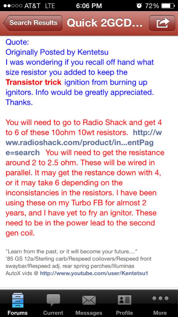
If you open up the base of your coilpack you will see the built-in balast resistor. The aim is to replace this with either a single 1 Ohm 10W resistor (Kent - gsl-se-addict), or perhaps 4x 10 Ohm 10W(Sam - bad83) resistors in parallel. Some people have mounted them externally to help with heat dissipation, to materials such as copper or aluminium - being careful not to short any wires to them! The built-in resistor is 0.35 Ohms.
info from : Transistor Trick for 2GCDFIS
I was actually ready to built one and wasn't aware of that
Although there was a lot of active development of the auto-switching and max limiting circuitry, there was a flaw in the design in that the coilpack fires on the trailing edge of the signal. In order to achieve variable timing seperate to the J109, the circuit required would be quite complex or a micro-controller would be required, which could make the device more expensive and difficult to put together. Stick with the simple initial circuits
See Below!The problem initially faced with the variable or fixed circuits was that the coilpack was entering current-limiting mode and this was generating a lot of heat - heat that was being made in the internal balast resistor, which would end up killing the coilpack. The solution to this is to change the balast resistor, or externally mount one, with suitable heatsink materials to help take the heat away from this.
Balast Resistor Details
If you open up the base of your coilpack you will see the built-in balast resistor. The aim is to replace this with either a single 1 Ohm 10W resistor (Kent - gsl-se-addict), or perhaps 4x 10 Ohm 10W(Sam - bad83) resistors in parallel. Some people have mounted them externally to help with heat dissipation, to materials such as copper or aluminium - being careful not to short any wires to them! The built-in resistor is 0.35 Ohms.
info from : Transistor Trick for 2GCDFIS
I was actually ready to built one and wasn't aware of that

Thread
Thread Starter
Forum
Replies
Last Post
Red-Dragon_Akuma
New Member RX-7 Technical
11
Sep 28, 2015 06:09 AM

