105 Amp Alternator Swap HOW TO – GM CS130
 02-06-06, 10:33 PM
#76
Full Member
Thread Starter

If that doesn't work, you could also go to any alternator rebuild shop and they should be able to swap the pulleys for you with another one that will fit for free, or just a couple bucks at most
 02-07-06, 07:30 AM
#78
Originally Posted by riceburner1r2001
whats funny but sucks i was at the junkyard again today and got n but after i pulled the plug from the lesabre it was just like big ern said, and then was looking at the alternator was looking good until i saw that the car was a 95 le sabre not 94. I didnt no if it would work so i hid it n a 7 for the mean time. and weird when i was there i saw a seven with a 100 amp fuse
you just lost me there buddy.
 02-12-06, 03:09 PM
#86
Originally Posted by Big_Ern
Now for the fun part… Wiring!
The stock alt has only 2 wires, whereas the GM alt has 4. However, only 2 of them are necessary, so this part is fairly simple.
The stock alt has 2 terminals marked R and L (you can see the L terminal marked in pic 1). L is connected to the stock alternator warning lamp on the dash, and R is connected to a switched ignition source.
The GM wiring is as follows:
S – Sensor wire (connected to the battery or output terminal of the alternator)
F – not necessary
L – Same as our stock alt
P – not necessary
Run a wire from the S terminal on the new alternator to the output terminal of the battery as shown in pic 2. (note: I was not able to get a proper GM plug in time for my install so I used some female spade connectors instead. I do not recommend this and will be replacing it with the proper plug soon)
Finally cut off your old alt plug and solder the L wire to the new L wire on the GM alt.
Note: The GM harness is in the order mentioned above (S-F-L-P) starting from the red wire as shown in pic 2.

 05-24-07, 01:08 PM
#91
Registered Offender
Join Date: Jul 2006
Location: Bishopville, SC
Posts: 689
Likes: 0
Received 0 Likes
on
0 Posts
Will this fit? (lookee here) Only thing it says 70 to 80 amps at idle. Does that mean at higher revs you get more amps?
thanks
thanks
http://cgi.ebay.com/ws/eBayISAPI.dll...MEWN:IT&ih=020
05-24-07, 06:06 PM
#93
Registered Offender
Join Date: Jul 2006
Location: Bishopville, SC
Posts: 689
Likes: 0
Received 0 Likes
on
0 Posts
Another mounting option - no cost
Thanks for this write up, I did this today! I just wanted to throw out an alternative way to mount this alternator. With a hacksaw, grinder, and some elbow grease I just lopped off the back end of the big ear. This allowed me to use the stock bolts and spacer, so I didn't have to purchase any hardware. It also gave me a solution to a small PITA that I run into whenever I want to remove my carb.
In this pic you can see the CS130 on the left with the big ear at the bottom, stock alt is on the right. The pigtail for the CS130 is also shown.
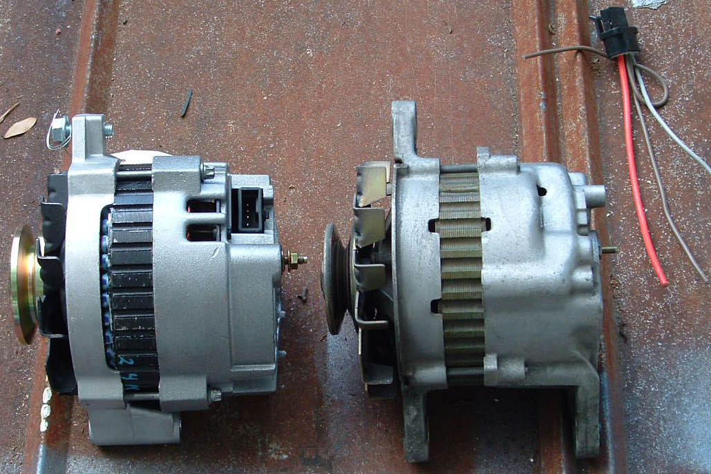
In this one you can see the chunk of material I removed from the ear. The modified ear is now at the top of this pic.
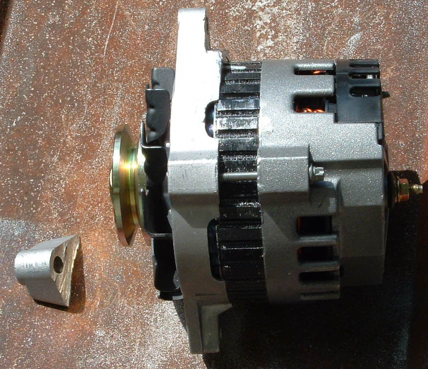
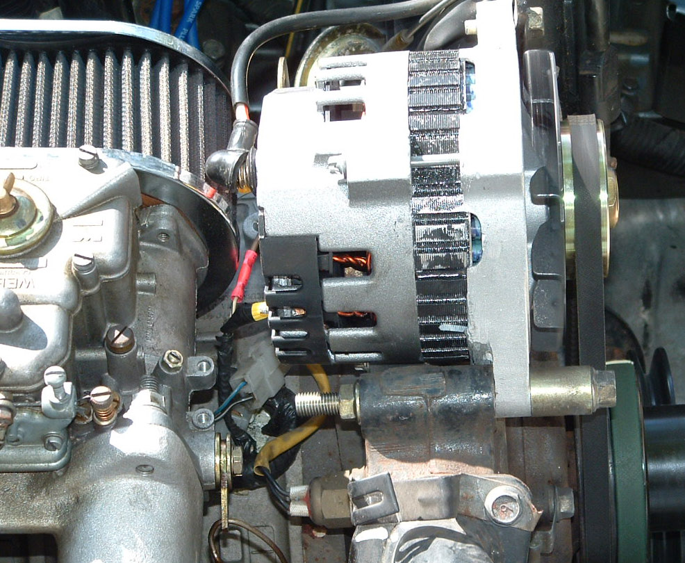
Here it is mounted up. Note that the spacer is now in front of the alternator rather than behind the iron. I did this for the sole purpose of now having the clearance to easily remove my Weber carb without having to unbolt the alternator. The spacer can of course go back in where it was before, this is a matter of personal choice.
In this pic you can see the CS130 on the left with the big ear at the bottom, stock alt is on the right. The pigtail for the CS130 is also shown.
In this one you can see the chunk of material I removed from the ear. The modified ear is now at the top of this pic.
Here it is mounted up. Note that the spacer is now in front of the alternator rather than behind the iron. I did this for the sole purpose of now having the clearance to easily remove my Weber carb without having to unbolt the alternator. The spacer can of course go back in where it was before, this is a matter of personal choice.
07-12-07, 11:33 AM
#95
"1ST GENS" THE REAL RX-7!
Join Date: Apr 2005
Location: long island
Posts: 861
Likes: 0
Received 0 Likes
on
0 Posts
I did this on monday. After driving back from rotorfest and sitting in traffic with the A/C on high, and the radio on with both amps running I noticed my volt gauge was hanging right at 12V+.
So I head on down to the Junkie and pick up a CS130 for $40 then off to parts plus for a pig tail $10 then to the marina for a stainless steel 3"bolt $2.
$52 later and about 10 minutes with the dremel and I am good to go. Nice easy bolt in
fairly easy wiring ( I replaced the ring terminal with a gold plated one ) and shrink wrapped all the wires.
After the start up the voltage is not any higher (still hangs around the 13.5V+ mark) but I can put on all the accesories and it will still hang at 13.5V+.
So I guess that means it works. It dosent look bad in there although it is a little BIG. I am going to clean it up with the dremel this weekend and I will post a couple of pics.
Jason
07-16-07, 05:04 PM
#97
Full Member
Thread Starter
I didn't scale them cause I'm not that ****, but they did feel about the same weight. No Idea how much they are, but lets guss stock 10lbs, the cs130 was barely lighter, so maybe 1lb. Not a difference at all. You could shave much more wight by goin on diet
Glad to hear it worked out for you so well. I did mine the same way by shaving the big ear on the cs130 and moving that tube spacer thingy, too. might have just wrote it differently so people that aren't great fabricators wouldn't shy away.
Great pics btw
Thanks for this write up, I did this today! I just wanted to throw out an alternative way to mount this alternator. With a hacksaw, grinder, and some elbow grease I just lopped off the back end of the big ear. This allowed me to use the stock bolts and spacer, so I didn't have to purchase any hardware. It also gave me a solution to a small PITA that I run into whenever I want to remove my carb.
In this pic you can see the CS130 on the left with the big ear at the bottom, stock alt is on the right. The pigtail for the CS130 is also shown.
In this one you can see the chunk of material I removed from the ear. The modified ear is now at the top of this pic.
Here it is mounted up. Note that the spacer is now in front of the alternator rather than behind the iron. I did this for the sole purpose of now having the clearance to easily remove my Weber carb without having to unbolt the alternator. The spacer can of course go back in where it was before, this is a matter of personal choice.
Glad to hear it worked out for you so well. I did mine the same way by shaving the big ear on the cs130 and moving that tube spacer thingy, too. might have just wrote it differently so people that aren't great fabricators wouldn't shy away.
Great pics btw
04-20-11, 05:41 PM
#100
Rotary Enthusiast
iTrader: (8)
Join Date: Jan 2007
Location: Burlington, Ontario
Posts: 847
Likes: 0
Received 0 Likes
on
0 Posts
For those wanting to do the 140 amp upgrade. I found out after purchasing one, that the shaft diameter is 5/8 not 1/2 inch like our alternators shaft. So either, you have to re-size your pulley's hole from 1/2 inch to 5/8 or get a 105 amp alternator which has a 1/2 inch shaft.

