HOW TO: Remove/Replace Suspension Bushings
 08-04-03, 06:20 PM
#1
Super Snuggles
Thread Starter
HOW TO: Remove/Replace Suspension Bushings
Let me start off by saying that there is definitely more than one way to remove and replace suspension bushings, and if you're not inclined to take your car or suspension parts to a local shop or just like to do your own work, then this write-up is for you.
For the do-it-yourselfer, there are three main methods, so let's cover them first and the pros and cons associated with each.
1) Sockets and Bolts
This is by far the most cost effective method, but probably also the most frustrating and definitely the most time consuming.
For those who aren't familiar with this method, it involves pulling the bushings out of the suspension components by tightening a nut on a bolt passing through a socket smaller than the bushing on one side and a socket larger than the bushing on the other. The force of tightening the nut "pulls" the bushing into the larger socket.
Max Cooper has by far and away the best write-up on this method, and you can find that here...
http://www.maxcooper.com/rx7/how-to/...lls/index.html
His write-up only covers the pillow bushings, but the method is much the same for the rest of the bushings in the suspension.
As will become apparent after reading through it, the cost savings comes from using a couple bags of hardware from your local home improvement store. On the other hand, the time consuming nature of this method arises from the need to continually change washers or bolts to get the right combination for leverage, as well as replacing washers that are destroyed in the process. Max says he went through 50-100 of them.
2) Mazda's SST (Special Service Tool)
Mazda's SST for replacing the suspension bushings is PN 49 F034 2A0. This part number includes a dozen or so "sub-parts". All are listed in the service manual, and the order in which they are to be used is shown in the illustrations.
This method is almost identical to the first, but the kit includes all the cup and press sizes required without trying to find sockets to match, and doesn't require a trip to the hardware store.
The downside is that it is also somewhat time consuming, and then there's the cost... with my 15% discount from Mazda, my cost is $369.07 ($434.20 retail). Unfortunately, it really isn't good for anything else after you're finished using it.
3) Hydraulic Press
This is the method I'll be covering in this thread, and while not exactly cheap, it's not as expensive as the SST method, it's fast, and at the end of the job, you've got a tool that you can use for several purposes besides playing with bushings.
The major expenses are the hydraulic press (more on that in a moment), a few pieces of bar stock (again, keep reading), and any sockets you don't already have in your arsenal. So without further ado, let's begin...
 08-04-03, 06:31 PM
#2
Presses are for wimps!
No, just kidding -- I didn't want to remove my suspension arms when I was doing the pillow *****, and I didn't have a press handy anyway. I did use a press to install the JimLab bushing set.
-Max
No, just kidding -- I didn't want to remove my suspension arms when I was doing the pillow *****, and I didn't have a press handy anyway. I did use a press to install the JimLab bushing set.
-Max
08-04-03, 06:33 PM
#3
Super Snuggles
Thread Starter
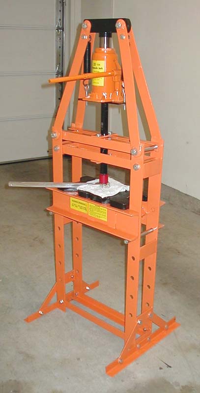
The first tool you'll need is a hydraulic press. I chose a 20-ton press from Harbor Freight (PN 37999-0VGA) for $200.00. The bonus is that shipping is free on this 132 lb. press, it's big enough to get the job done quickly and easily, but it's not so big that it's going to consume a large part of your garage or shop with its footprint.
While you could get by with a smaller press more than likely, a 20-ton press will give you enough leverage and work space to make the job easy, and that's what we're looking for. As an alternative, the Harbor Freight 12-ton A-frame press (PN 1667-2VGA) is only $109.99 but might make working with the bigger suspension pieces more difficult.
The press comes with 2 steel arbor plates shown in the picture below, underneath the white shop towel beneath the polished trailing arm.
Last edited by jimlab; 08-04-03 at 06:35 PM.
08-04-03, 07:23 PM
#4
Super Snuggles
Thread Starter
I've spent the past half hour trying to post the next picture, and all I've gotten for my trouble is a caution that I've already posted the picture (but neither it nor the post show up anywhere) and should not post it again...
I'll wait until the forum has a bit less load on it to post the rest of the series.
I'll wait until the forum has a bit less load on it to post the rest of the series.
08-04-03, 07:43 PM
#5
Super Snuggles
Thread Starter
The next thing I did was buy five pieces of 1 inch square by 1 foot long (1x1x12") of 1018 carbon steel bar stock from McMaster-Carr (www.mcmaster.com) for about $10-12 ea., if I recall correctly. You could get these from any local steel supply shop, I'm sure.
The bars make it easy to position support beneath the hydraulic ram and set up configurations that would be impossible otherwise, making removal of some of the bushings possible as will be shown later.

The bars make it easy to position support beneath the hydraulic ram and set up configurations that would be impossible otherwise, making removal of some of the bushings possible as will be shown later.
Last edited by DamonB; 05-02-07 at 09:57 AM.
08-04-03, 07:49 PM
#6
Super Snuggles
Thread Starter
The last thing required was several sockets. The sizes are listed below, as well as their outside diameters (in parentheses), so that if you happen to have a different brand, you'll have an easier time finding an equivalent size to use.
1) Crafstman 1/2" drive, 7/8" socket (1.17" dia.)
2) Craftsman 3/4" drive, 1 3/16" socket (1.56")
3) Pittsburgh 1/2" drive, 32mm socket (1.64")
4) Craftsman 3/4" drive, 1 7/16" socket (2.06")
5) Craftsman 3/4" drive, 1 11/16" socket (2.30")
Note: These are only the sizes used for the rear suspension. I will not be covering the front control arms at this time.
08-04-03, 07:58 PM
#7
Super Snuggles
Thread Starter
There are six identical pillow ball bushings in the rear suspension, so let's start there since many people with higher mileage will probably be replacing these eventually. There are two on each rear lower control arm (outer two bushings) and one on each rear upper control arm (outermost bushing).
These are all protected on each side with a rubber dust cover. To remove the dust covers, gently insert a small flat blade screwdriver between the center post which the bolt passes through and the rubber seal, and gently push the tip over toward an edge and pop the seal up. It doesn't take much, and you don't want to scratch or damage the aluminum control arm. Once you do one, you'll get the hang of it.
Once they're off, your control arms will look like this:
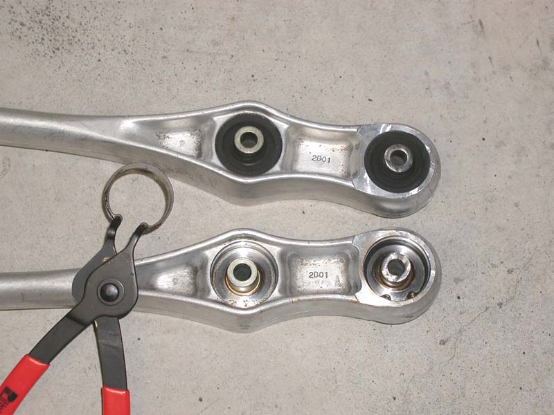
Clean out all the excess grease that's under the cover, and you'll reveal the C-shaped retention clips. Use a pair of snap ring pliers (I've got the cheapy Harbor Freight Pittsburgh set) to compress and remove the C-clip as shown in the picture above.
Once you've done this to all six pillow bushings, you're ready to start pressing them out.
These are all protected on each side with a rubber dust cover. To remove the dust covers, gently insert a small flat blade screwdriver between the center post which the bolt passes through and the rubber seal, and gently push the tip over toward an edge and pop the seal up. It doesn't take much, and you don't want to scratch or damage the aluminum control arm. Once you do one, you'll get the hang of it.
Once they're off, your control arms will look like this:
Clean out all the excess grease that's under the cover, and you'll reveal the C-shaped retention clips. Use a pair of snap ring pliers (I've got the cheapy Harbor Freight Pittsburgh set) to compress and remove the C-clip as shown in the picture above.
Once you've done this to all six pillow bushings, you're ready to start pressing them out.
Last edited by DamonB; 05-02-07 at 09:58 AM.
Trending Topics
08-04-03, 08:08 PM
#8
Super Snuggles
Thread Starter
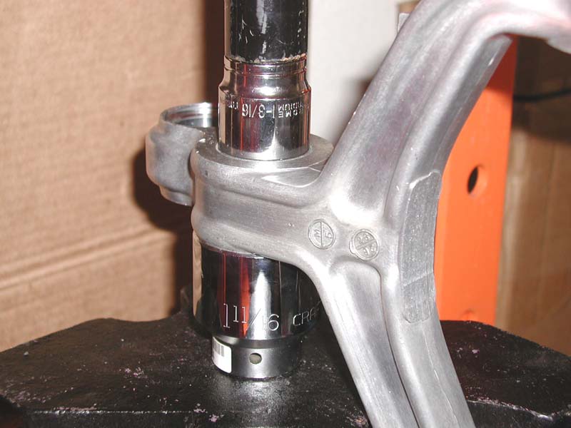
For this operation, I put the height adjustment pins (see the silver pins underneath the arbor in the picture of the press above) in the 2nd hole from the top.
As you can see in the picture below, I used two of the pieces of bar stock, one on each side, with their inner edges just outside the diameter of the bushing for maximum support. You can position them by lowering the press ram until it just touches the socket enough to hold it in place, and then move the two pieces of bar stock as necessary by feel, or by looking beneath to ensure that they won't interfere with the bushing as it is pressed out. This is the same procedure you'll follow for all the bushings. Obviously the space beneath the bushing must be clear, or it's not going anywhere.
Please note that to keep stuff from bouncing all over the place, you might want to put a small bucket with a folded shop rag or two in the bottom of it under the arbor to catch the bushing and/or socket when they fall through.
Also note that this is the outermost bushing on the rear lower control arm, the socket being used is the 1/2" drive 7/8" Craftsman, and you want to press on the side opposite the side you just removed the C-clip from, which is the larger opening.
Center the socket on the bushing and press away. These bushings pop out very easily with almost no strain.
Last edited by DamonB; 05-02-07 at 09:59 AM.
08-04-03, 08:17 PM
#9
Super Snuggles
Thread Starter
The next pair of pillow bushings use the same setup (two pieces of bar stock, 7/8" socket, same height setting on the arbor) and are the outer bushing on each rear upper control arm. The picture below shows the arrangement for removal...

Last edited by DamonB; 05-02-07 at 09:59 AM.
08-04-03, 08:29 PM
#10
Super Snuggles
Thread Starter
For the last two pillow bushings (center bushings in the rear lower control arms), I had to drop the arbor down one hole, and placed one of the arbor plates directly underneath the ram.
Underneath the towel is the large 1 11/16" Craftsman 3/4" drive socket which I used to catch the bushing and as a support for the arm during pressing. As you can see in the picture below, there is no flat surface to rest the arm on, so the towel protects the aluminum while the big socket supports it from beneath.
Once again, the socket used to press out the bushing is the 1/2" drive 7/8" Craftsman.
Last edited by DamonB; 05-02-07 at 10:00 AM.
08-04-03, 08:42 PM
#11
Super Snuggles
Thread Starter
And here's the result of all your hard work so far. Note that when you replace these pillow bushings (PN FD01-26-220) that the tapered side of the center section goes in first, and flat side will face out for the C-clip to seat on. Installation is pretty much the opposite of removal, so I won't be covering it here.

Last edited by DamonB; 05-02-07 at 10:00 AM.
08-04-03, 08:56 PM
#12
Super Snuggles
Thread Starter
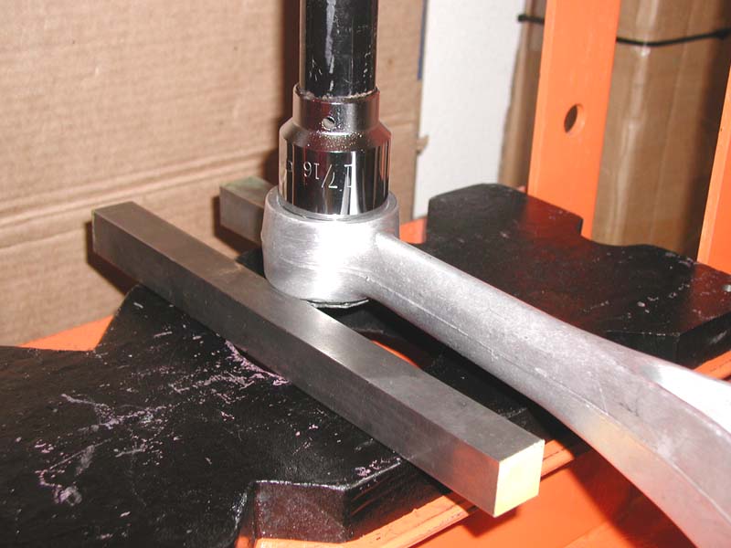
Next on the list are the shock mount bushings in the rear upper control arms (center bushings). In the picture below, you can see that I'm still using the arbor plate, the arbor is still at the same height as the last pair of pillow bushings, and I still have the 1 11/16" socket on the arbor plate.
Time for the first correction: the 1 3/16" socket is not a Craftsman 3/4" drive... it's a Pittsburgh 1/2" drive. My apologies. The outside diameter is still correct (1.56"). The forum lag has been so bad that it's taken too long to post this stuff, and I can't edit the socket list any more.
As you can see in the picture below, the 1 3/16" socket is used to press the shock mount bushing into the larger socket below. Pretty straight forward, and this one doesn't require much effort either. You can also press from either side with the same result.
Last edited by DamonB; 05-02-07 at 10:01 AM.
08-04-03, 09:08 PM
#13
Super Snuggles
Thread Starter
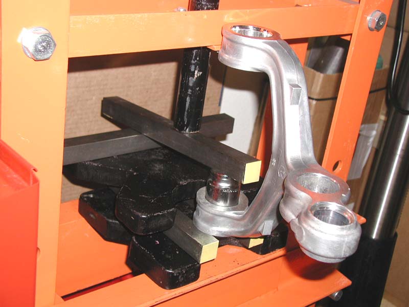
The next bushings are where it gets a little tricky. The rear upper control arm bushings which bolt to the rear subframe can only be pressed out from the inside because they have a flange on the outer edge. As you can see below, I had to get a little creative with the arbor plates and bar stock to manage these.
The arbor is still on the same setting, with one arbor plate on top of it with the large "U" cut-out in the plate pointing out to give the bushing somewhere to go. I then used two of the bar stock pieces as spacers, put the other arbor plate on top with the large "U" cut-out outward again, and set up a fulcrum with two more pieces of bar stock.
This setup looks a little scary in the picture, but it was rock solid because of the weight of the pieces and because the upper bar on the fulcrum is at a very shallow angle. Also, the rear bar is directly over the cross bar of the arbor, and I'm pressing directly down onto the other cross bar of the arbor.
Last edited by DamonB; 05-02-07 at 10:01 AM.
08-04-03, 09:15 PM
#14
Super Snuggles
Thread Starter
Here's a close-up from the other side. As you can see, I'm using the 1/2" drive Pittsburgh 32mm socket for these bushings.
By holding the control arm with one hand (which isn't going anywhere until pressure is released) and working the bottle jack with the other, you eliminate the damage that could be caused to the suspension component when the bushing pops free.
These bushings are a very tight fit and will suddenly come loose with a loud pop after seemingly going nowhere. Take it slow and easy and apply steady pressure to them until they pop. The bar being pushed on stays right on top of the socket and nothing came flying off the press in all four I did last week, but use proper safety precautions and wear a bulletproof vest anyway if you try this at home.
Last edited by DamonB; 05-02-07 at 10:02 AM.
08-04-03, 09:18 PM
#15
Super Snuggles
Thread Starter
And here's what you've got when you're done. Assuming you haven't reinstalled any bushings yet, that is.
Note the flanges on the rear upper control arm bushings that require them to be pressed out from the inside.

Note the flanges on the rear upper control arm bushings that require them to be pressed out from the inside.
08-04-03, 09:27 PM
#16
Super Snuggles
Thread Starter
Most of you won't ever replace the following bushings, but if you ever had to, here's how it's done.
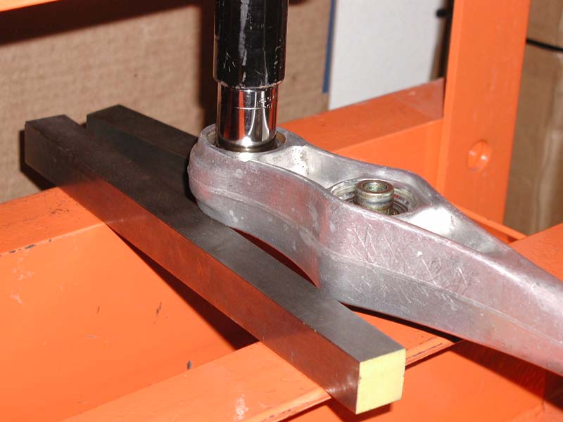
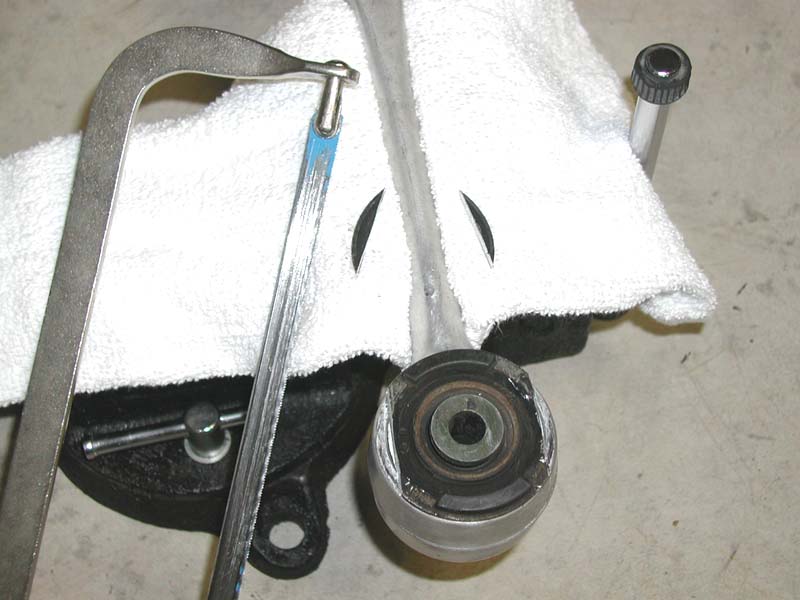
The inner "damping" bushing on the rear lower control arms has a flange that interferes with any attempt to press it out without modification. There's just no place to rest it on, so even the shop manual states that you have to cut away the flange with a hacksaw.
I started with two parallel (to the length of the control arm) cuts, just inside the edge of the aluminum. You can judge how thick it is by looking at the other side. The trick here is to cut very carefully until you're almost down to the aluminum, but not into the aluminum. At that point, you can use a punch or a chisel and a hammer to knock the flange up away from the control arm, tap it back down, and so on until it fatiques and breaks away. This will prevent damage to the aluminum control arm.
In the picture below, you can see the two slivers of flange I cut away sitting on the towel, and you can see that on both sides I've fully exposed the aluminum of the control arm and even cut into the diameter of the bushing sleeve to a small degree. This will give you maximum support for pressing the bushing out when resting the control arm on two pieces of bar stock.
It's not shown, but I went ahead and cut away the rest of the flange, just in case I had to use a larger socket to press into, but as you'll see in the next post, it turned out to be unnecessary.
Last edited by DamonB; 05-02-07 at 10:02 AM.
08-04-03, 09:35 PM
#17
Super Snuggles
Thread Starter
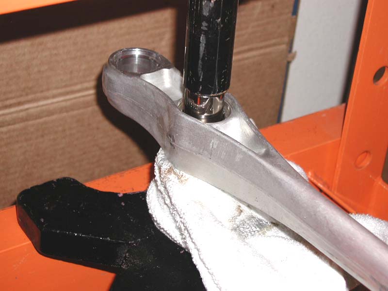
As shown above, use a vice to hold the lower control arm while you're cutting, and use a razor blade to slice off the two rubber "bumpers" on each side (the other two at top and bottom are still shown in place) remaining to get down to the metal of the flange.
Once that's done, here's how you get rid of the bushing. I left the arbor on the lower setting, put both arbor plates on with the larger "U" cut-outs facing in (to make a circle), and then used two pieces of bar stock to support the control arm with the flange side down. The diameter of the 3/4" drive Craftsman 1 7/16" socket works perfectly to press these out, because there's not much sleeve to press against.
These come loose pretty easily, none of the fanfare of the rear upper control arm bushings here. Again, put something under the arbor to catch the bushing and the socket when they fall through.
Note: The replacement parts are the rear lower control arm "damping" bushing (PN FD01-28-460) and rear lower control arm "stopper" (PN FD01-28-461), which is just the rubber "doughnut" that presses onto the other side of the bushing opposite the flange.
Last edited by DamonB; 05-02-07 at 10:03 AM.
08-04-03, 09:45 PM
#18
Super Snuggles
Thread Starter
And once again, here's the end result. Note that in the picture below, the flanges for the inner damper bushings have been completely cut away.

08-04-03, 09:55 PM
#19
Super Snuggles
Thread Starter
Now you're probably wondering where the 1 11/16" socket comes in... "You can't be telling us to run out and buy one just to catch other bushings with, can you?" You're right, I'm not.
Unfortunately I didn't take any pictures during the process, but the 3/4" drive Craftsman 1 11/16" socket is the perfect size for pressing out the differential mount bushings, and I bought it when I installed a set of my Nylon replacements for a friend, so there you are.
So that concludes my write-up for now. I won't be reinstalling bushings until my suspension components have been polished and probably hard coat anodized, but I'll continue this thread and post the pictures when that time comes.
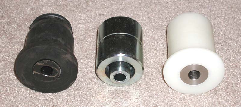
I will probably be doing something with the front control arms too since I have to press my Nylon bushings back out to make way for my custom pillow ball bushings (shown below in the center), and will post that here also.
Unfortunately I didn't take any pictures during the process, but the 3/4" drive Craftsman 1 11/16" socket is the perfect size for pressing out the differential mount bushings, and I bought it when I installed a set of my Nylon replacements for a friend, so there you are.
So that concludes my write-up for now. I won't be reinstalling bushings until my suspension components have been polished and probably hard coat anodized, but I'll continue this thread and post the pictures when that time comes.
I will probably be doing something with the front control arms too since I have to press my Nylon bushings back out to make way for my custom pillow ball bushings (shown below in the center), and will post that here also.
Last edited by DamonB; 05-02-07 at 10:03 AM.
08-06-03, 08:00 AM
#21
Lives on the Forum
I am going on vacation for a week. This thread will go into our bookmarks and be archived when I get back, just give it some more time to see some "live" action 
08-06-03, 01:48 PM
#24
Rotary Freak
Join Date: May 2002
Location: Houston
Posts: 1,742
Likes: 0
Received 0 Likes
on
0 Posts
You know, that hydraulic press looks like a fancily mounted bottle jack. I wonder if someone could Mcgyver up some way to use a standard bottle jack?
Anyways, two questions.
How long do stock bushings last? At what point would you change them out?
Why is the JimLab set so expensive? I don't know that much about the manufacturing, and was curious. I also don't know the OEM cost of a replacement set.
Anyways, two questions.
How long do stock bushings last? At what point would you change them out?
Why is the JimLab set so expensive? I don't know that much about the manufacturing, and was curious. I also don't know the OEM cost of a replacement set.
08-06-03, 02:51 PM
#25
Former Rx7 *****
Join Date: Nov 2001
Location: Mississauga
Posts: 4,534
Likes: 0
Received 0 Likes
on
0 Posts
Originally posted by PVerdieck
Why is the JimLab set so expensive? I don't know that much about the manufacturing, and was curious. I also don't know the OEM cost of a replacement set.
Why is the JimLab set so expensive? I don't know that much about the manufacturing, and was curious. I also don't know the OEM cost of a replacement set.

