separating fiction from reality... a couple of days on the DYNO
 06-15-12, 07:27 AM
#901
Racing Rotary Since 1983
Thread Starter
iTrader: (6)

thanks and GTK...
i will discuss (next week) the various points raised w Rick at Exhaust Gas Technologies re K efficacy and will use whatever they suggest will work best for my app. Rick and Dennis at EGT service the top of the racing pyramid. i will pass on anything relevant.
i really want to puke when i look at a typical IAT log that shows 27 from 2000 to 8600. given my comparison between pre and post AI, real data is needed.
howard
Last edited by Howard Coleman; 06-15-12 at 07:38 AM.
 06-15-12, 02:27 PM
#902
Wastegate John
iTrader: (13)
Join Date: Feb 2008
Location: Long Island NY 11746
Posts: 2,979
Likes: 0
Received 9 Likes
on
9 Posts
thanks and GTK...
i will discuss (next week) the various points raised w Rick at Exhaust Gas Technologies re K efficacy and will use whatever they suggest will work best for my app. Rick and Dennis at EGT service the top of the racing pyramid. i will pass on anything relevant.
i really want to puke when i look at a typical IAT log that shows 27 from 2000 to 8600. given my comparison between pre and post AI, real data is needed.
howard
i will discuss (next week) the various points raised w Rick at Exhaust Gas Technologies re K efficacy and will use whatever they suggest will work best for my app. Rick and Dennis at EGT service the top of the racing pyramid. i will pass on anything relevant.
i really want to puke when i look at a typical IAT log that shows 27 from 2000 to 8600. given my comparison between pre and post AI, real data is needed.
howard
I am interested to see what the numbers are as well, but I dont think there will be as a dramatic of a difference between a GM air sensor and a k type thermocouple.
The reason I dont think there will be a significant rise in temp from a few runs on the dyno is because the air exiting the turbo is hot, however it pases through an intercooler that acts like a huge heat-sink for the few second duration of the dyno pull and it then able to cool off again due to the air from the fan in front of the dyno as the tuner makes adjustments. Then another pull is made to the cooled off intercooler again.
So in conclusion I am not too surprised that the temps are fairly steady for 1 run on the dyno. However, I think there should be some sort of change but not drastic enough to really worry about.
06-15-12, 07:46 PM
#904
Racing Rotary Since 1983
Thread Starter
iTrader: (6)
i have run the stock FD sensor relocated to the post IC tube... i have no idea as to other sensors... i do know the K will get it done and will be interested to see the temp immediately after the turbo at various boost levels, how it is effected by the pre turbo AI and how much help i get from the IC.
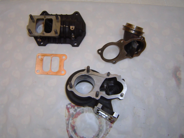
i did pick up the finished manifold this aft.
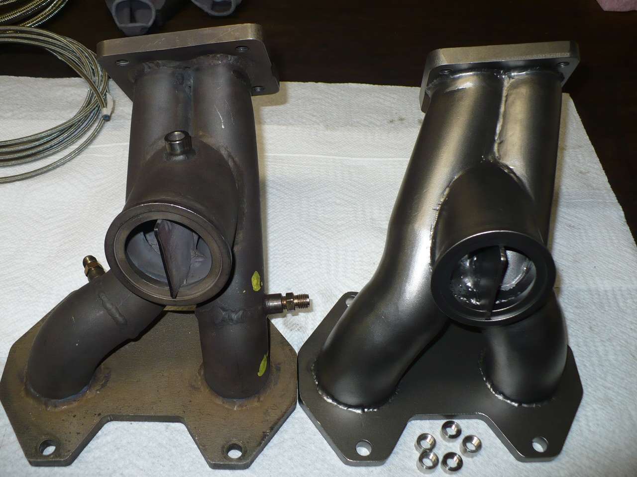
the newer manifold has 51% more inside runner area as well as having less bends. since it locates the often cherry red turbine housing within 3/8 inch of the front LIM runners a Mica heat shield is essential. zero heat penetrates Mica. the manifold enables a 9 inch by 7 inch K&N filter straight forward of the compressor making the preturbo injector a kill shot..
the final component will be a box for the filter so it draws essential outside air but that will have to wait a bit as we need to get rolling and we dyno, of course, w the hood open.
hc
Last edited by Howard Coleman; 06-15-12 at 08:21 PM.
06-15-12, 10:48 PM
#906
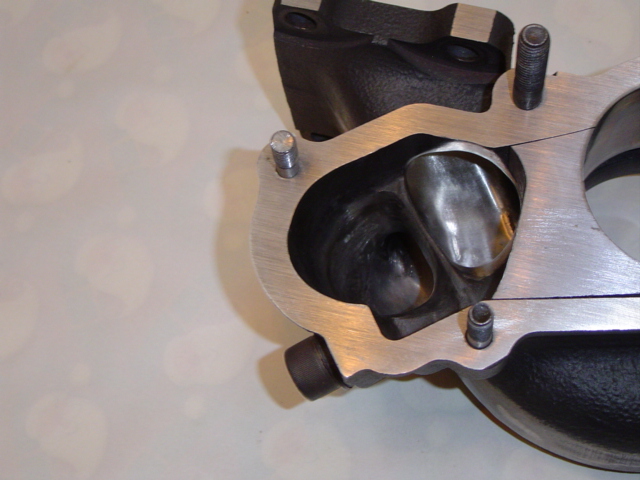
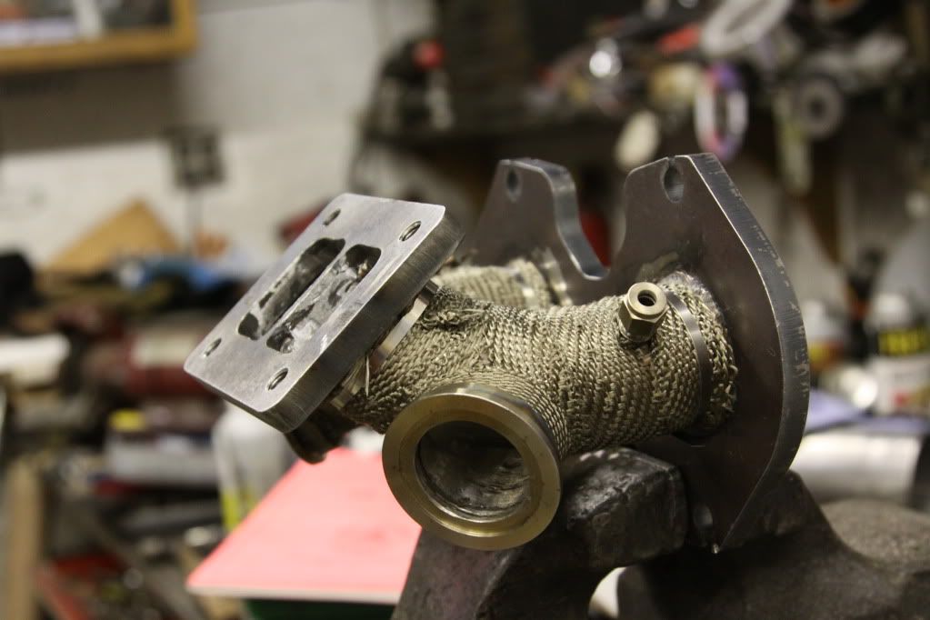
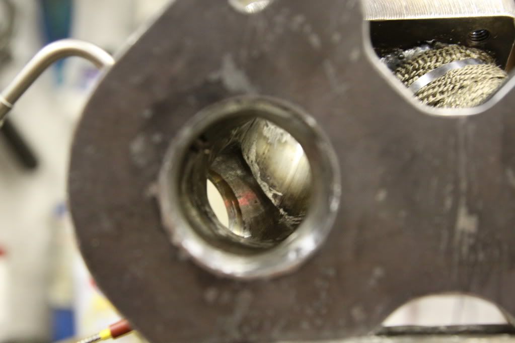
I can't say this any way without sounding really negative which isn't my goal, but that is the worst wastegate flow path I have ever seen.
It appears it is 135deg cheated radius junction to the runner with no lead in.
If you have a free flowing turbo back exhaust (3.5-4") it will likely boost creep as it will be easier for the high velocity exhaust to continue out the turbo even as the preturbo pressure stacks up than reverse flow and go out the wastegate.
Also, that runner divider to the wastegate will likely rip in half once you start racing the car.
I am speaking from my own mistakes on both these points.
I adapted a 60mm wastegate to S5 divided Hyrbid turbo and still had boost creep (90 deg junctions to wastegate) until I ported the manifold/turbo 2x volume to reduce velocity as well as direct exhaust to favor the wastegate port.
Well, actually it still creeps to 17psi on 12psi spring if I take my 3" catback off my 3.5" downpipe and put the 3.5" one on.
I also tried the divided runner to wastegate twice. First one was welded in as you have it. After that broke I did another that was floating on a ring at the WG end so it could expand as I reasoned thermal expansion broke the welds. Nope, it tore in half as well.
I know my experience is with a little 400rwhp hp turbo, but I think it will apply on a bigger one as well.
my follies-
06-15-12, 11:34 PM
#907

I do have to agree with Blue TII. The wastegate placement is a complete 180 from flow. I understand that with your manifold design you are shooting for as equal length runners as possible with a full divided set up but this manifold will not direct enough flow through the wastegate. If you would like to go full divided, equal length, with as less bends as possible the I believe a twin wastegate set up would be far superior. Engineering seems to always be taken into consideration with you Howard as I always enjoy reading your posts and research. But I think there are some things that do not need to be entirely over thought  Take a look at GoodfellaFD3S's manifold made by Sean at A Spec and I have a feeling you'll reconsider
I look forward to your dyno day and your results! And thank you for doing such an expensive experiment for the community. I have read this entire thread and can't imagine the $$$ spent on this project being done for this community.
Thanks
Matt
Take a look at GoodfellaFD3S's manifold made by Sean at A Spec and I have a feeling you'll reconsider I look forward to your dyno day and your results! And thank you for doing such an expensive experiment for the community. I have read this entire thread and can't imagine the $$$ spent on this project being done for this community.
Thanks
Matt
06-16-12, 08:55 AM
#908
Racing Rotary Since 1983
Thread Starter
iTrader: (6)
"And you're wondering why they didn't respond?" (using stock FD sensor)
if the open element GM IAT sensor works well let's see some logs. i have no bias as to the method of getting real time charge air temps. if the GM sensor produces multiple readings per second it sounds like the proper choice... let's see the data.
as to wastegate placement... it is a balancing act.
ideally you want no wastegate port in your main runners as the hole(s) greatly disturbs flow to the turbo. as an old NA guy i am very sensitive to flow disruption. that's why my BOV port is on the flat end tank surface of my IC. the last thing you want is a 2 inch hole in a 2.75 tube just before the elbow.
of course WG venting is necessary to control boost level and creep. ideally you want as little as possible to get the job done. i purposely situated my WG to that end. the advantage of my location is that it decreases flow interruption. there are some additional internal flow guidance features in the WG area.
of course the issue w a disadvantaged WG port is... does it do the job. if it doesn't, as has been correctly posted, you have boost creep. i do think the bottom line on that has to be actual data.
fortunately, i have the Jan 16 dyno session for data. here it is....
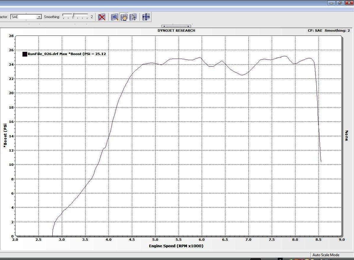
i don't see any creep at 24/25 psi. no boost creep w a dis-advantaged WG =s a win for primary turbo flow. the boost variations, fairly minor, were due to AFRs not being perfect. it was our second run at that level so the tuning wasn't quite on the target in all cells. nevertheless, a standard deviation of boost was only .65 psi from 5000 to 8300.
part of the reason for the performance advantage is my WG selection... a Tial 60 MM. piston area is King w re to WGs.
the Tial 60 has 86% more area than a 44. my manifold will only be sold w a 60.
as far as 2 WGs... have at it if you wish. i have no interest in all the additional plumbing. further, the heat sensitive end of my WG is far away from any heat.
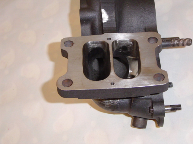
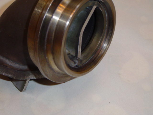
as to the divider coming apart...
that's the last thing that will happen. the divider is part of a primary piece of the manifold. primary as the inner dividing wall between the upper primary runners.
again, getting back to actual data from theory... the manifold design worked very well as evidenced by flat EGTs from 5000 to 8000+. flat and no engine threatening around 1550 F. that tells me the manifolding system delivered high flow, low resistance. part of the reason is the disadvantaged WG design.
it will be interesting to see how the 51% increase in runner internal cross section effects flow.
howard
if the open element GM IAT sensor works well let's see some logs. i have no bias as to the method of getting real time charge air temps. if the GM sensor produces multiple readings per second it sounds like the proper choice... let's see the data.
as to wastegate placement... it is a balancing act.
ideally you want no wastegate port in your main runners as the hole(s) greatly disturbs flow to the turbo. as an old NA guy i am very sensitive to flow disruption. that's why my BOV port is on the flat end tank surface of my IC. the last thing you want is a 2 inch hole in a 2.75 tube just before the elbow.
of course WG venting is necessary to control boost level and creep. ideally you want as little as possible to get the job done. i purposely situated my WG to that end. the advantage of my location is that it decreases flow interruption. there are some additional internal flow guidance features in the WG area.
of course the issue w a disadvantaged WG port is... does it do the job. if it doesn't, as has been correctly posted, you have boost creep. i do think the bottom line on that has to be actual data.
fortunately, i have the Jan 16 dyno session for data. here it is....

i don't see any creep at 24/25 psi. no boost creep w a dis-advantaged WG =s a win for primary turbo flow. the boost variations, fairly minor, were due to AFRs not being perfect. it was our second run at that level so the tuning wasn't quite on the target in all cells. nevertheless, a standard deviation of boost was only .65 psi from 5000 to 8300.
part of the reason for the performance advantage is my WG selection... a Tial 60 MM. piston area is King w re to WGs.
the Tial 60 has 86% more area than a 44. my manifold will only be sold w a 60.
as far as 2 WGs... have at it if you wish. i have no interest in all the additional plumbing. further, the heat sensitive end of my WG is far away from any heat.
as to the divider coming apart...
that's the last thing that will happen. the divider is part of a primary piece of the manifold. primary as the inner dividing wall between the upper primary runners.
again, getting back to actual data from theory... the manifold design worked very well as evidenced by flat EGTs from 5000 to 8000+. flat and no engine threatening around 1550 F. that tells me the manifolding system delivered high flow, low resistance. part of the reason is the disadvantaged WG design.
it will be interesting to see how the 51% increase in runner internal cross section effects flow.
howard
06-16-12, 09:48 AM
#909

I think it's about time to close the books on theories/equations/data charts/redesigning parts 10x/etc and getting the thing on the dyno!!!!!!!!!
I apologize as I've stopped reading most of the thread and I've just been checking in for dyno numbers/videos...can I get some footnotes on the next dyno date and what's left on getting everything buttoned up?
I apologize as I've stopped reading most of the thread and I've just been checking in for dyno numbers/videos...can I get some footnotes on the next dyno date and what's left on getting everything buttoned up?
06-16-12, 10:15 AM
#910
"And you're wondering why they didn't respond?" (using stock FD sensor)
if the open element GM IAT sensor works well let's see some logs. i have no bias as to the method of getting real time charge air temps. if the GM sensor produces multiple readings per second it sounds like the proper choice... let's see the data.
as to wastegate placement... it is a balancing act.
ideally you want no wastegate port in your main runners as the hole(s) greatly disturbs flow to the turbo. as an old NA guy i am very sensitive to flow disruption. that's why my BOV port is on the flat end tank surface of my IC. the last thing you want is a 2 inch hole in a 2.75 tube just before the elbow.
of course WG venting is necessary to control boost level and creep. ideally you want as little as possible to get the job done. i purposely situated my WG to that end. the advantage of my location is that it decreases flow interruption. there are some additional internal flow guidance features in the WG area.
of course the issue w a disadvantaged WG port is... does it do the job. if it doesn't, as has been correctly posted, you have boost creep. i do think the bottom line on that has to be actual data.
fortunately, i have the Jan 16 dyno session for data. here it is....
i don't see any creep at 24/25 psi. no boost creep w a dis-advantaged WG =s a win for primary turbo flow. the boost variations, fairly minor, were due to AFRs not being perfect. it was our second run at that level so the tuning wasn't quite on the target in all cells. nevertheless, a standard deviation of boost was only .65 psi from 5000 to 8300.
part of the reason for the performance advantage is my WG selection... a Tial 60 MM. piston area is King w re to WGs.
the Tial 60 has 86% more area than a 44. my manifold will only be sold w a 60.
as far as 2 WGs... have at it if you wish. i have no interest in all the additional plumbing. further, the heat sensitive end of my WG is far away from any heat.
as to the divider coming apart...
that's the last thing that will happen. the divider is part of a primary piece of the manifold. primary as the inner dividing wall between the upper primary runners.
again, getting back to actual data from theory... the manifold design worked very well as evidenced by flat EGTs from 5000 to 8000+. flat and no engine threatening around 1550 F. that tells me the manifolding system delivered high flow, low resistance. part of the reason is the disadvantaged WG design.
it will be interesting to see how the 51% increase in runner internal cross section effects flow.
howard
 06-16-12, 10:25 AM
#911
Wastegate John
iTrader: (13)
Join Date: Feb 2008
Location: Long Island NY 11746
Posts: 2,979
Likes: 0
Received 9 Likes
on
9 Posts
i don't see any creep at 24/25 psi. no boost creep w a dis-advantaged WG =s a win for primary turbo flow. the boost variations, fairly minor, were due to AFRs not being perfect. it was our second run at that level so the tuning wasn't quite on the target in all cells. nevertheless, a standard deviation of boost was only .65 psi from 5000 to 8300.
Well I would not expect there to be boost creep when the target boost is in the upper range of what most people run on their cars.
I would like to see a log of a run at around 10PSI where the exhaust backpressure is significantly lower.
06-16-12, 12:01 PM
#912
Racing Rotary Since 1983
Thread Starter
iTrader: (6)

here's the lowest boost we ran. i believe it was off the spring. i don't see significant boost creep. BTW, the 23/24 run was nowhere near full boost w the WG spring setup. i am comfortable we will be able to run 30 psi w no problem. the point being the boost controller was not maxed out and was controlling boost at that level.
and if you want to run 10 psi please feel free to use a different manifold. my design is for one bar to 30.
howard
06-16-12, 12:40 PM
#913
If you have boost creep at 24 PSi, your manifold seriously sucks or your wastegate is insufficient. If you'd shown that graph at 10-12 PSi with the same setup, that would mean something. You of all people with your data and theories should know this Howard.... We all know you want to run higher boost so boost creep isn't on the list of your concerns so don't bother mentioning it unless your running 10-12 PSi.
I am curious why your boost is so unstable though. Tuning shouldn't really affect boost that significantly as its controlled by a separate mechanical system. How is your boost controller hooked up? Both the top port and the bottom port of the wastegate are being sourced at the compressor I assume?
thewird


 06-16-12, 07:42 PM
#917
"And you're wondering why they didn't respond?" (using stock FD sensor)
if the open element GM IAT sensor works well let's see some logs. i have no bias as to the method of getting real time charge air temps. if the GM sensor produces multiple readings per second it sounds like the proper choice... let's see the data.
if the open element GM IAT sensor works well let's see some logs. i have no bias as to the method of getting real time charge air temps. if the GM sensor produces multiple readings per second it sounds like the proper choice... let's see the data.
The units are all metric, manifold pressure absolute on a 100-101.3kpa day at 0m above sea level.
Manifold pressure in kpa starts at 101.3kpa with the engine off. 201.3kpa = 1 bar of boost ie 14.5psiG. Peak boost seen in that run is 251.8kpa ie 21.8225psiG atove a full sea level atmosphere.
That boost pressure is the result of a pair of Tial MVS 38mm loaded with 1.4bar springs they should achieve ~20.3psiG however they get more than this and then drop off as the EMP stacks up. I now have the 1.7bar springs loaded into my gates with the over boost cut out turned off.
The ONLY mods to this block are
mild runner work and port shape done to already big factory 12A tall ports
Nitrided MFR 17.5mm oil pump
S4 turbo water pump
Side Clearanced rotors
3 windowed Rear stationary gear
The run you are seeing data from was my PB run of 11.828@124.30mph with a 1.972 60ft time.
06-17-12, 04:07 AM
#919
Truth be told I'm just as likely to tune to ECU to disregard the air temperature reading, I'm not totally convinced that that temperature is of much relevance to the actual charge temperature by the time it gets to the intake port.
When I was using the mazda sensor I found that the air temperature correction was acting like a 2nd stage of coolant temperature which caused rich mixtures during warmup rather than being a good flag for reduction timing when the charge was really hot or removing fuel because the charge is less dense.
06-17-12, 04:37 AM
#920
Its in the intercooler pipe about 10cm from the throttle body. My throttle body snout also has an rx-7 air temp sensor in it but it heat soaks to the point it reads hot when the engine bay is hot rather than when the blowing past the sensor is hot.
Truth be told I'm just as likely to tune to ECU to disregard the air temperature reading, I'm not totally convinced that that temperature is of much relevance to the actual charge temperature by the time it gets to the intake port.
When I was using the mazda sensor I found that the air temperature correction was acting like a 2nd stage of coolant temperature which caused rich mixtures during warmup rather than being a good flag for reduction timing when the charge was really hot or removing fuel because the charge is less dense.
thewird
06-17-12, 09:01 AM
#921
Racing Rotary Since 1983
Thread Starter
iTrader: (6)
ideally i want to know the temperature of the charge air entering the intake ports.
i think the problem w the stock IAT sensor is it just doesn't react fast enough so when things heat soak there is a period of time before the stock sensor reads the actual charge air temp and not all the surrounding aluminum.
changing the sensor, rather than the location, would seem to be the best approach.
i do think being able to have the actual charge air temps would be very helpful w re to tuning.
based primarily on theweird's experience i am going to read IAT from my previously plugged stock location but will do it w a K setup.
howard
 06-17-12, 06:39 PM
#923
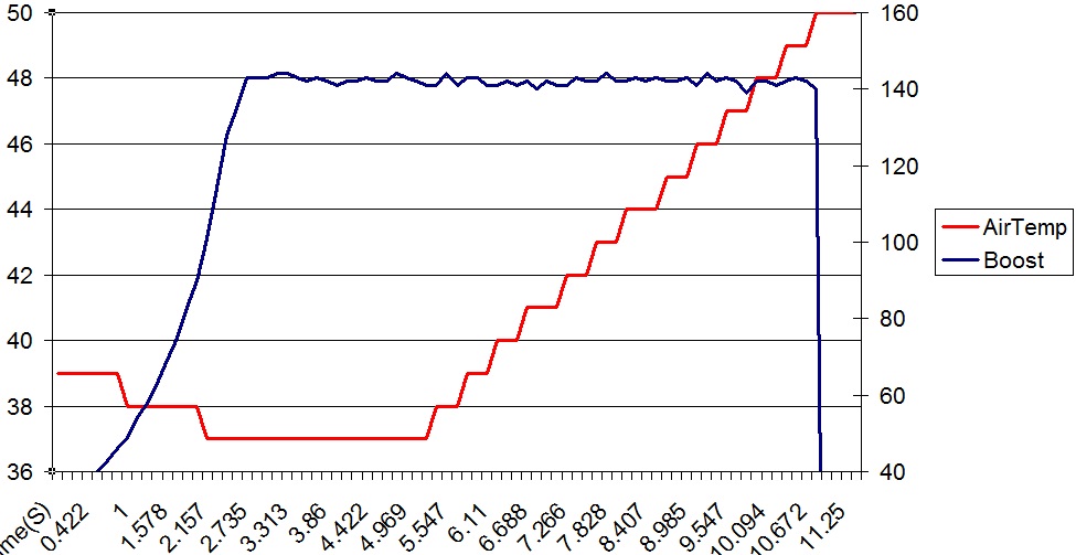
Here is a pull in 4th gear with pump gas & tap water injection @ 1.4 bar. Triumph sensor in stock location. I don't remember if this was on a dyno or on the street but I'm gonna guess on the dyno based on the rate of climb of the AIT's. It usually takes a few laps around Mosport to get close to 50 degrees, not one pull hehe.
Boost on the right (x100) and air temp on the left.
thewird
Boost on the right (x100) and air temp on the left.
thewird
06-17-12, 08:04 PM
#924
Jobro beat me to it. The GM sensor works well, is inexpensive and readily available. I'm sorry, but I must admit that I derive a small amount of sadistic joy in seeing you trying to reinvent the wheel.
We're using three of the GM sensors in this Miata. Pre-turbo inlet, compressor outlet, and intake manifold. Three traces shown in the log.
We're using three of the GM sensors in this Miata. Pre-turbo inlet, compressor outlet, and intake manifold. Three traces shown in the log.
06-18-12, 07:48 AM
#925
Here is a pull in 4th gear with pump gas & tap water injection @ 1.4 bar. Triumph sensor in stock location. I don't remember if this was on a dyno or on the street but I'm gonna guess on the dyno based on the rate of climb of the AIT's. It usually takes a few laps around Mosport to get close to 50 degrees, not one pull hehe.
Boost on the right (x100) and air temp on the left.
thewird
Boost on the right (x100) and air temp on the left.
thewird
