manifold runner size affect on spool and flow
 11-28-11, 08:45 AM
#1
manifold runner size affect on spool and flow
So a little while back, i decided to ditch my S5 p-trim hybrid setup for a full T4 turbo. I found an ERC divided T4 manifold with a divided T4 .84 p-trim turbine housing. I reused the hifi 60-1/p-trim turbo i was using, just bolted it on to the new turbine housing. Full spool went from 3500rpm to 4500rpm, and it felt considerably laggier. Same turbo as before, only difference was manifold and turbine housing. I looked at the manifold and noticed it has 1.75" piping, or about 1500mm area
it is common knowledge that the larger your runner size between engine and turbo hotside means slower gas velocity and more peak flow capability, but smaller the runner size means faster exhaust velocity and better spool and low end.
so i took some measurements the other day
exhaust diffuser in housing area ~820mm
S5 exhaust manifold outlet area ~900mm
divided T3 flange area ~1100mm
divided T4 flange area ~1400mm
1.25" piping area ~800 mm
1.5" piping area ~1100 mm
1.75" piping area ~1500
2" piping area ~2000 mm
so the question is, do you gain anything by using a manifold with larger runners than factory? Isnt the ~820 mm exhaust diffuser the restriction?
 11-28-11, 09:15 AM
#2
so the question is, do you gain anything by using a manifold with larger runners than factory? Isnt the ~820 mm exhaust diffuser the restriction?
What are you referring to when you say the exhaust diffuser? You are referring to a standard turbo Rx-7 sleeve/housing, a Cosmo housing (13B-RE/20B) or a non turbo with the port insert?
11-28-11, 02:55 PM
#4
so the question is, do you gain anything by using a manifold with larger runners than factory?
We sure would like to know as well! Do you have before and after dyno sheets? Could you get them?
Pictures of your T4 manifold/housing set up?
It is interesting to me because you are going from a ~T25 sized 1.0 AR stock housing to a tighter .84 AR in a T4 housing and T4 manifold on the same exhaust wheel size.
Is it possible the restriction from the tighter .84 AR on the T4 frame turbo will limit flow as much or more than the smaller volume of the stock ~T25 manifold/housing?
If not, at what point would the crossover in restriction be? How would a well 1.0 AR T3 manifold and exhaust housing compare to the .84 AR T4 manifold/housing.
Also, what role does the wastegate play. I am assuming you are using an external wastegate on the T4 manifold which could help the top end power and modified stock internal wastegates on the stock manifold/housing.
When tuning my friend's turbo Prelude the tuner was able to add more timing and lean it out to make power once he added an external WG to his set up. Also, after he added his external WG-having his exhaust cut out on the downpipe open or closed made nearly no difference, whereas it was a large gain with it open on the internal WG.
I noticed a drop off in lower rpm boost response when to stop boost creep I ported out my S5 manifold/housing to favor flow to my 60mm external gate- but interestingly, my peak boost rpm was the same.
11-28-11, 04:14 PM
#5
Some charts to consider from production engines...
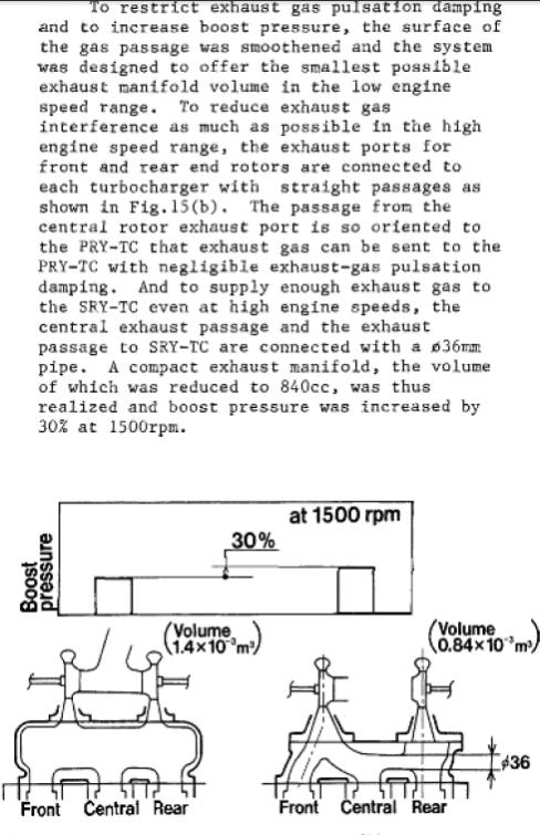
During development of the 20B, Mazda tried to minimize the exhaust manifold diameter (and presumably the sleeves) in order to improve response. They also tried to orient the runners so that exhaust pulsation effects would remain strong. In the case of a 2 rotor with a divided manifold the pulsation effects and lack of exhaust gas interference help throughout the rpm range.

During development of the early Buick 3.8 turbo engines (predecessor to Grand National engine), GM experimented with different turbine A/R's to see how they affected spool and exhaust gas temperature. A high exhaust gas temperature will affect the life of components. With a divided exhaust manifold and turbo you have the benefit of not really having to worry about hot exhaust gas blowing back into the engine during overlap.

During development of the Fiat 1.4 turbo engine of about 5 years ago, engineers experimented with different A/R combinations to see how they affected spool. This engine, like most boosted engines today, was designed for low end torque and fuel economy.
When developing the Honda K23 turbo engine (Acura RDX), Honda engineers decided to implement a variable A/R system similar in concept to what's used on the s4 T2 Rx-7:


You can see that turbine A/R and exhaust manifold area have a big effect on torque characteristics and can certainly affect backpressure significantly.
During development of the 20B, Mazda tried to minimize the exhaust manifold diameter (and presumably the sleeves) in order to improve response. They also tried to orient the runners so that exhaust pulsation effects would remain strong. In the case of a 2 rotor with a divided manifold the pulsation effects and lack of exhaust gas interference help throughout the rpm range.
During development of the early Buick 3.8 turbo engines (predecessor to Grand National engine), GM experimented with different turbine A/R's to see how they affected spool and exhaust gas temperature. A high exhaust gas temperature will affect the life of components. With a divided exhaust manifold and turbo you have the benefit of not really having to worry about hot exhaust gas blowing back into the engine during overlap.
During development of the Fiat 1.4 turbo engine of about 5 years ago, engineers experimented with different A/R combinations to see how they affected spool. This engine, like most boosted engines today, was designed for low end torque and fuel economy.
When developing the Honda K23 turbo engine (Acura RDX), Honda engineers decided to implement a variable A/R system similar in concept to what's used on the s4 T2 Rx-7:
You can see that turbine A/R and exhaust manifold area have a big effect on torque characteristics and can certainly affect backpressure significantly.
11-28-11, 08:36 PM
#6
no i did not get any dyno sheets on the ERC manifold. it had a single 46mm wastegate with open dump. my ERC manifold looks like the first one in this thread
http://www.driftworks.com/forum/part...amer-pipe.html
so not only does it have larger diameter over factory, but the runners are a lot longer with more volume
http://www.driftworks.com/forum/part...amer-pipe.html
so not only does it have larger diameter over factory, but the runners are a lot longer with more volume
12-13-11, 08:17 PM
#7

hmm interesting.
this is going to be a naive response, but i've seen a build on rx7club where a guy prefferred long exhaust runners to the turbo because i guess it actually benefitted him most while getting off the gas... as in it maintained pressure to the turbo longer than it would with short runners......
again... i probably haven't analyzed the situation, but it somewhat makes sense...
but i'd think that longer intake runners are usually used to place the turbocharger away from the intake manifolds... decreasing intake air temps.
and of course they'd be smoother than the stock log-type manifolds with the capability of in-line external wastegates.
Trending Topics
12-25-12, 02:21 PM
#8
im finally going to give my theory a try. i recently rebuilt my fd with s4 n/a rotors, and it makes my s5 creep really badly.. i already ordered the manifold parts: 1.3" id runners, 38mm wastegates, and going to run a t3 stage III turbine. i still have the 60-1 compressor and p-trim wheels, and i was going to order a t3 p-trim housing for a direct comparison to factory. i will post pics of the piping, it looks rediculously small
12-27-12, 03:34 PM
#9
Moderator
iTrader: (3)
Join Date: Mar 2001
Location: https://www2.mazda.com/en/100th/
Posts: 30,796
Received 2,574 Likes
on
1,830 Posts
im finally going to give my theory a try. i recently rebuilt my fd with s4 n/a rotors, and it makes my s5 creep really badly.. i already ordered the manifold parts: 1.3" id runners, 38mm wastegates, and going to run a t3 stage III turbine. i still have the 60-1 compressor and p-trim wheels, and i was going to order a t3 p-trim housing for a direct comparison to factory. i will post pics of the piping, it looks rediculously small
 12-27-12, 06:10 PM
#10
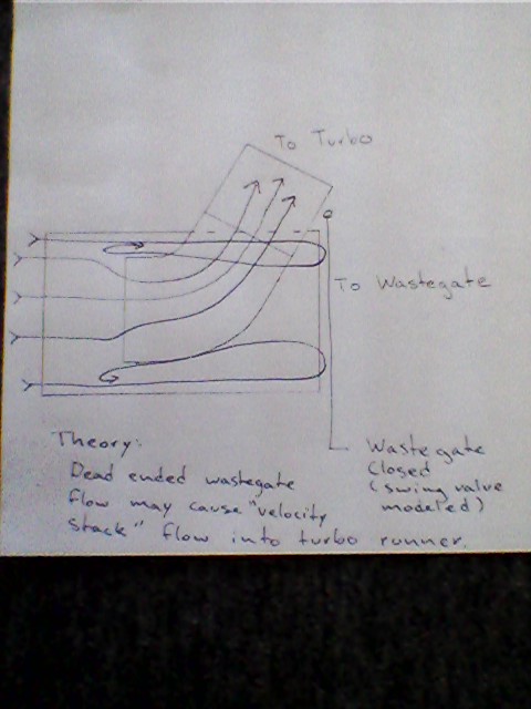
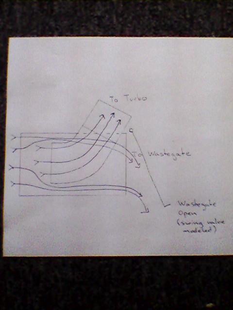
I think you will find it is very hard to control boost creep with the small 1.3" ID runners as you have such high exhaust velocity it will not want to deviate course to turn into the wastegate runners.
If you have the flow favor the wastegate (like straight shot into wastegate out of motor and a bend up into the turbo) it might work, but then you have that very high velocity flow creating huge turbulence at the wastegate runner junction which will cause a restriction.
Here is the crazy idea I had for a manifold for a small turbo with adequate wastegate flow to prevent boost creep.
12-27-12, 07:10 PM
#11
Racing Rotary Since 1983
iTrader: (6)

"if you look in the newer part of HC's turbo thread he went from whatever he was running (2"?) to the next size up, so between the two of you maybe we learn something "
i do expect to learn something as to runner area. i have all the data from the dyno re spool, back pressure, egts as well as power and rpm from my first manifold which had 2.035 sq inches of cross sectional area.
my new manifold has an increase of 65% at 3.355 sq inches.
the port is 3.04.
runner velocity pickup comes w increased drag so we will see how it nets out.
howard
The following users liked this post:
EZAS (07-05-22)
12-28-12, 08:55 AM
#12
here is a sho tof the piping..
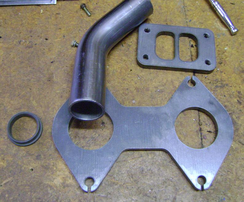
its all just cheap mild steel, once i get something that works, i will order with SS and have it professionally made. the piping actually has 1.37" ID, so its more like 1.45 sq in area, about 4% bigger than factory S5 manifold
as far as wastegate placement, ideally i would like copy the factory S5 manifold, where the one of the rotors had a straight shot to the turbine wheel with no restrictions due to bends. but it may be difficult to fit wastegates and turbo without hittingn the frame rail or engine mount
the second option i was considering was more the traditional way, angling upward at 45 deg angle to the turbo, with wastegate angled down at -45 deg. and basically try to minimize manifold volume as much as possible
im not an expert at all, but i think volume has a big effect. very cool idea, but it looks like the wastegate passage may add too much volume, which will lessen the effect of the exhaust pulses on the turbine wheel. I want to try to put the wavegate flanges as close as possible to the pipe, so with them closed, the flow is close as possible to have only pipes without wastegates
its all just cheap mild steel, once i get something that works, i will order with SS and have it professionally made. the piping actually has 1.37" ID, so its more like 1.45 sq in area, about 4% bigger than factory S5 manifold
as far as wastegate placement, ideally i would like copy the factory S5 manifold, where the one of the rotors had a straight shot to the turbine wheel with no restrictions due to bends. but it may be difficult to fit wastegates and turbo without hittingn the frame rail or engine mount
the second option i was considering was more the traditional way, angling upward at 45 deg angle to the turbo, with wastegate angled down at -45 deg. and basically try to minimize manifold volume as much as possible
I think you will find it is very hard to control boost creep with the small 1.3" ID runners as you have such high exhaust velocity it will not want to deviate course to turn into the wastegate runners.
If you have the flow favor the wastegate (like straight shot into wastegate out of motor and a bend up into the turbo) it might work, but then you have that very high velocity flow creating huge turbulence at the wastegate runner junction which will cause a restriction.
Here is the crazy idea I had for a manifold for a small turbo with adequate wastegate flow to prevent boost creep.
If you have the flow favor the wastegate (like straight shot into wastegate out of motor and a bend up into the turbo) it might work, but then you have that very high velocity flow creating huge turbulence at the wastegate runner junction which will cause a restriction.
Here is the crazy idea I had for a manifold for a small turbo with adequate wastegate flow to prevent boost creep.
12-28-12, 09:24 AM
#13
Rotary Enthusiast

so would it be safe to assume that smaller ID runners with more velocity would make a quicker spool. (blanket statement) the smaller runners will then shift the power curve to the left? ( because of reduced overall flow?)
And we associate spool with torque?
So a practical use for this set up would for an autox car you have a small turbo and small runners and you only use the redline RPM to carry you into the next corner to not shift.
And we associate spool with torque?
So a practical use for this set up would for an autox car you have a small turbo and small runners and you only use the redline RPM to carry you into the next corner to not shift.
12-28-12, 03:56 PM
#14
yes, with a stock exhaust port, i believe you gain nothing by going bigger than 1.3" ID. if you go smaller, you increase velocity, gain low end, but hurt top end. but going bigger than 1.3" does nothing but lose low end. HC's ports are opened up to 3" area, or about 1.95" ID. so for his porting, his optimum pipe inner diameter is 1.95", any bigger and he is just creating extra volume that reduces velocity
thats the theory anyway
thats the theory anyway
12-28-12, 04:17 PM
#15
I've used lots of different sizes, even built cars at the same time with different tubing with identical engines, tunes, turbos etc.
Its always been my experience that anything bigger than the inlet to the turbo flange does nothing for extra power, just adds noticeable lag. Keep in mind I always try and use gentle bends, and the least amount of bends as possible.
Its always been my experience that anything bigger than the inlet to the turbo flange does nothing for extra power, just adds noticeable lag. Keep in mind I always try and use gentle bends, and the least amount of bends as possible.
 12-28-12, 05:58 PM
#16
If a T3, T4, T6 ect, manifold was made you would be using different diameter tubing for each?
I've used lots of different sizes, even built cars at the same time with different tubing with identical engines, tunes, turbos etc.
Its always been my experience that anything bigger than the inlet to the turbo flange does nothing for extra power, just adds noticeable lag. Keep in mind I always try and use gentle bends, and the least amount of bends as possible.
Its always been my experience that anything bigger than the inlet to the turbo flange does nothing for extra power, just adds noticeable lag. Keep in mind I always try and use gentle bends, and the least amount of bends as possible.
02-03-13, 08:30 AM
#17
well i got the new manifold finished, but the flange must have got warped during welding so there is an exhaust leak at the moment. but what ive found so far is reducing runner size from 1.75" to 1.38" resulted in 500 rpm quicker spool, even with a bad exhaust leak. it hits 6psi by 2000 rpm, stage III turbine, v-trim compressor. I still need to turn up the boost to see if top end is hurt at all by smaller runners. But just running off the wastegate springs, there is no sign of creep at all. but the way i did the manifold, you can see straight through the exhaust port to the wastegate exits. and on the front rotor, you can see the turbo through the exhaust port also
02-03-13, 09:52 AM
#18
Racing Rotary Since 1983
iTrader: (6)
"anything bigger than the inlet to the turbo flange does nothing for extra power"
agree.
the T4 flange is approx 2.69 sq inches area for one inlet (of two)
the exhaust port is 3.04 sq inches.
my small runner manifold (2012) had 2.035 sq inches of runner area with chamfers on the flange. 20 psi boost at 4281 rpm. this was on a 23 psi limited run. i will say that in spite of the small runner cross sectional area the setup made very good power at 8650 w low stable EGTs at 1550 F.
my large runner manifold (2013) has 3.35 sq inches so it is 10% larger than the port. the only area of the manifold that features 3.35 is from the flange thru the bends.
once the manifold straightens toward the turbo flange it linearly necks down to the turbo flange area.
i do think excess manifold volume is a negative drag just like excess turbo to throttle body (ex- IC) volume is a similar drag. low volume and straight are the operating fundamentals.
we were on the dyno last week initially and i do hope to have some comparative info shortly.
"flange must have got warped during welding"
surface grinding after construction is pretty much a must...
by turbo selection and manifold construction it is possible to shift the torque curve anywhere you want on the rpm scale. Ford's Ecoboost is a good example... a really small turbo that raises the torque curve and shifts it massively left so the motor feels like a larger displacement motor. you could easily do this for autocross should you want more power at lower revs.
proper turbo sizing, port configuration, manifold configuration all allow you to set your torque curve and location anywhere you want given you realize there are offsets. specific application of course is the key driver.
my setup which is street friendly (21 mpg highway) sets peak torque at 6450.
manifolding is an interesting subject and i look forward to your data gxl90rx7.
howard
02-25-13, 01:19 PM
#21
RX 4BPT

Join Date: Feb 2011
Location: Huddersfield, England
Posts: 293
Likes: 0
Received 0 Likes
on
0 Posts
Yes running to a T4 divided flange. Need to take my current crap manifold off and measure the exhaust port. I think 2" will be the right size, I need to have my WG coming forward instead of backwards. So having to build my own manifold instead of modifying this one again.
02-25-13, 03:52 PM
#22
"Our manifolds are built with schedule 40 1.5 Pipe( .145" wall) 304SS. We have found this is the most optimal size I.D. tubing/pipe for a T4 2 rotor. We use the least amount of bends possible, and do not cheat any radii. Both flanges are also extremely well hand ported, and the I.D. of the flange matches the I.D. of the OEM exhaust sleeve. Our experience has shown us this manifold design has the highest velocity possible, and therefore the quickest " spool ". -Quoted From Turblown.
02-25-13, 05:11 PM
#23
sch40 1.5 pipe is 1.6" inner diameter. Turblowns new cookie cutter manifolds have over 3x more volume than factory
https://www.rx7club.com/2nd-generati...folds-1025646/
https://www.rx7club.com/2nd-generati...folds-1025646/
02-25-13, 05:47 PM
#24
I have tried everything possible from 38mm up to 56mm id tubing, If you are running a divided T4 housing the best overall performer we have found is 45mm. We saw gains on our 13B two rotor FC manifolds the moment we switched over from standard 1.5" sizes those manifolds are a straight shot pretty much to the turbo with basically one bend used to mate to the T4. We tried them at 54mm as well and the cars felt "mushy" with no real gain. On a T6 divided 54mm works very well this obviously with a heavier ported engine. If it is a heavy ported engine you can start larger than 45mm and taper it down some but not much under 45mm otherwise WG placement will be critical. Two things to consider, 1) Running a smaller diameter inlet (manifold entry) on the larger exhaust port outlet, 2) When getting down to anything below 1.5" id you will start to have to pay attention to WG flow, as in the WG will need to be the priority, I know this because I've done it. You can offset this some by going to a larger A/r but you will still need to pay attention to WG flow on such a small diameter. IMO and this is just me knowing what I know, I would look at reworking the exhaust port sleeves first if bumping velocity is what your after. That being said it is the harder problem to solve when choosing between pipe diameter and making exhaust sleeves.
~S~
~S~
Last edited by Zero R; 02-26-13 at 01:31 PM.

Thread
Thread Starter
Forum
Replies
Last Post
Jeff20B
1st Generation Specific (1979-1985)
73
09-16-18 07:16 PM
[For Sale] Scratch & Dent, Used, and Open-Box Sale!
SakeBomb Garage
Vendor Classifieds
5
08-09-18 05:54 PM
rx8volks
Canadian Forum
0
09-01-15 11:02 PM