Rotary Peak Pressure Location ATDC
 06-04-10, 05:21 PM
#1
"Elusive, not deceptive!”
Thread Starter
Rotary Peak Pressure Location ATDC
Does anyone have any information on where the peak pressure should be located on a Rotary?
On a piston engine it is accepted to be located about 12°-15° ATDC depending on combustion chamber and piston shape and size.
It seems that I read someplace that for a Rotary it was around 45° ATDC but I’ll be darned if I can find it now.
Any help would be appreciated,
Barry
On a piston engine it is accepted to be located about 12°-15° ATDC depending on combustion chamber and piston shape and size.
It seems that I read someplace that for a Rotary it was around 45° ATDC but I’ll be darned if I can find it now.
Any help would be appreciated,
Barry
 06-05-10, 03:29 PM
#2
Senior Member
Join Date: Nov 2008
Location: Czech republic
Posts: 357
Likes: 0
Received 0 Likes
on
0 Posts
 06-05-10, 04:01 PM
#3
Rotary Enthusiast
oh boy,, great questions, anybody got any answers?
would peak chamber pressure be in rotor angle??
or peak press. be in E-shaft angle??
does it have to be in relation to TDC,or someplace else?
we come up with one question and open up 3 more.
seems rotary engines are from the Klingon empire.
what planet was Wankel born on? (thats a good question).
would peak chamber pressure be in rotor angle??
or peak press. be in E-shaft angle??
does it have to be in relation to TDC,or someplace else?
we come up with one question and open up 3 more.
seems rotary engines are from the Klingon empire.
what planet was Wankel born on? (thats a good question).
06-05-10, 04:47 PM
#4
"Elusive, not deceptive!”
Thread Starter
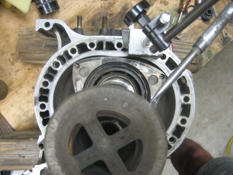
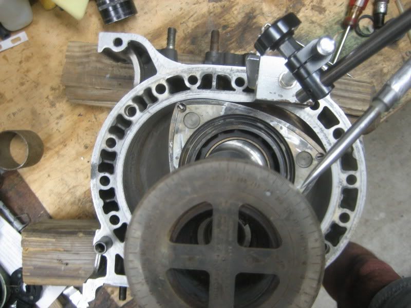
I wondered if since the piston engine has it's peak at 15° ATDC, it might follow that our rotor, being geared 3:1 that it's 15° ATDC would be the eccentric shaft's 45° ATDC.
15° ATDC of eccentric shaft rotation doesn't look like much leverage.
 06-05-10, 05:15 PM
#5
"Elusive, not deceptive!”
Thread Starter
oh boy,, great questions, anybody got any answers?
would peak chamber pressure be in rotor angle??
or peak press. be in E-shaft angle??
does it have to be in relation to TDC,or someplace else?
we come up with one question and open up 3 more.
seems rotary engines are from the Klingon empire.
what planet was Wankel born on? (thats a good question).
would peak chamber pressure be in rotor angle??
or peak press. be in E-shaft angle??
does it have to be in relation to TDC,or someplace else?
we come up with one question and open up 3 more.
seems rotary engines are from the Klingon empire.
what planet was Wankel born on? (thats a good question).
Here is what 45° ATDC looks like! Looks like more leverage possibility.
 06-05-10, 05:49 PM
#6
I've often wondered this same question. Whatever it is, I'll guess that it's too late and/or too long to take full advantage of maximum cylinder pressures, hence relatively poor mechanical efficiency and torque output.
Not sure where you arrived at the 45^ figure regarding piston engines. The point of maximum leverage in a piston engine should be about 90^ ATDC (in Crank degrees), assuming an infinitely long connecting rod. For the real life scenario where the rod is relatively short, the max leverage typically occurs at about 70-->80^ ATDC for common rod ratios IIRC.
This is a very good question, because my impression is that it is this very consideration that leads to a reduced mechanical efficiency and lower overall efficiency than piston engines (and my impression is that it plays a larger role than thermal efficiency concerns in the rotarys' output).
....It seems that I read someplace that for a Rotary it was around 45° ATDC but I’ll be darned if I can find it now. ....
This is a very good question, because my impression is that it is this very consideration that leads to a reduced mechanical efficiency and lower overall efficiency than piston engines (and my impression is that it plays a larger role than thermal efficiency concerns in the rotarys' output).
06-05-10, 08:10 PM
#7
looking for 82-83 corolla
iTrader: (6)
Join Date: Aug 2005
Location: ar
Posts: 451
Likes: 0
Received 0 Likes
on
0 Posts
wasnt there a guy around looking at making a chamber pressure datalogger as a school project. i remember it cause it brought up a few sites for piston chamber pressure tests and what not for tunning showing normal system and what the press does during detination causing the damage of course. this could help with a good datalogging of both that and shaft angle in relation to each other.... wont be cheap but definatly beneficial.
interested
z
interested
z
Trending Topics
06-05-10, 09:44 PM
#8
This is a very good question, because my impression is that it is this very consideration that leads to a reduced mechanical efficiency and lower overall efficiency than piston engines (and my impression is that it plays a larger role than thermal efficiency concerns in the rotarys' output).
06-06-10, 12:15 AM
#9
Very interesting topic.
According to an old article on the yawpower.com website, it should be near 45 degrees?
That section of the site has been down for a few months, here's an archived version:
http://web.archive.org/web/200801011...m/dectech.html
According to an old article on the yawpower.com website, it should be near 45 degrees?
10. 90° ATDC The expansion cycle has started, and is already 45° past the point of maximum torque transfer to the eccentric shaft, which occured at 45° ATDC.
http://web.archive.org/web/200801011...m/dectech.html
06-06-10, 12:36 AM
#10
talking head
As the spark plug fires, initiating combustion, the fuel burns, and the pressure in the chamber increases. It is this pressure, reacted through the rotor, that spins the eccentric shaft creating horsepower. At approximately 45 degrees after top dead center, the rotor has the greatest mechanical advantage over the eccentric shaft. This is the point of maximum torque transfer to the eccentric shaft.
It is often stated that to maximize power output, peak cylinder pressure should occur at this point. This is a gross oversimplification, and does not consider the average torque transfer throughout the cycle.
This illustration (From "The Rotary Engine", by Kenichi Yamamoto) shows gas pressure and torque fluctuation throughout the expansion cycle. Note the torque reversal before TDC shown on the bottom chart. This illustrates the power required to compress the mixture as the chamber nears TDC. Maximum output will occur when the ratio of cylinder pressure after TDC, to cylinder pressure before top dead center is the greatest. If for instance we had the option of manipulating the cylinder pressure, we would want to place all of the pressure after TDC, centered at the point of maximum torque transfer, with none of the pressure ocuring before TDC.
In the real world we do not have this option because the fuel does not burn fast enough to complete the combustion process within such a narrow range. In order to achieve the greatest cylinder pressure during this period of high torque transfer, we must ignite the mixture well before TDC. At full throttle, ignition occurs at approximately 25 degrees before TDC. In that period between ignition, and TDC, the chamber volume is decreasing, compressing the mixture that has just been ignited. Compressing this burning mixture (Which is expanding.) requires a certain amount of power, but this power loss if offset by the increased pressure "Under the curve" after TDC.
If you look closely at the torque fluctuation chart, you can see that the rotor effectively transfers power to the eccentric shaft over a very narrow range. If you give this a bit of thought, you will realize that the power output of the engine can be increased by increasing flame speed. Increasing the flame speed will release the energy from the fuel in a shorter period of time. This will allow more effective use of this energy by timing the combustion process to more closely match the torque transfer curve of the rotor/eccentric shaft combination.
06-06-10, 07:23 AM
#11
Racing Rotary Since 1983
iTrader: (6)

a very interesting topic.
for sure from a mechanical aspect 45 degrees is the number for max advantage as the lever is a perfect radius at that point.
it would seem ideally you would want all the energy concentrated at exactly at that point as posited post 10.
there are other factors somewhat offpoint to post one, which relate to thermal considerations. cetain fuels (alcohol) burn more slowly but offer huge cooling so you settle for a longer power delivery and gain cooling (alcohol) or power (higher octane slower burning/racegas.)
in each case timing would be very different but ideally you would want the center of force to line up w the max mechanical advantage position.
Barry, watch out for the degree wheel... you can lose a month or two of your life messing w it and a rotary and a lucite plate.
hc
06-06-10, 02:08 PM
#12
"Elusive, not deceptive!”
Thread Starter
Thanks scotty305 and bumpstart .
Yes it was Paul Yaw's site where I first read it, now I remember.
And Howard
"Barry, watch out for the degree wheel... you can lose a month or two of your life messing w it and a rotary and a lucite plate.
hc "
Tell me about it! But this is what we do for fun. Or put another way, this is what we do for fun?
06-06-10, 08:37 PM
#14
http://papers.sae.org/912479 "A Performance Simulation for Spark Ignition Wankel Rotary Engine" that's a possibility, if you want to throw a little loot to answer the question
06-07-10, 11:40 AM
#15
Ideally, this is where you want maximum expansion of the combustion gases (pressure) to occur in order to extract the most mechanical energy.
06-07-10, 12:00 PM
#16
"Elusive, not deceptive!”
Thread Starter
http://papers.sae.org/912479 "A Performance Simulation for Spark Ignition Wankel Rotary Engine" that's a possibility, if you want to throw a little loot to answer the question
Rotarygod put me on to those papers, but I don't have this one you listed.
Thanks for the info.
Barry
06-07-10, 02:34 PM
#17
"Elusive, not deceptive!”
Thread Starter
I've often wondered this same question. Whatever it is, I'll guess that it's too late and/or too long to take full advantage of maximum cylinder pressures, hence relatively poor mechanical efficiency and torque output.
Not sure where you arrived at the 45^ figure regarding piston engines. The point of maximum leverage in a piston engine should be about 90^ ATDC (in Crank degrees), assuming an infinitely long connecting rod. For the real life scenario where the rod is relatively short, the max leverage typically occurs at about 70-->80^ ATDC for common rod ratios IIRC.
This is a very good question, because my impression is that it is this very consideration that leads to a reduced mechanical efficiency and lower overall efficiency than piston engines (and my impression is that it plays a larger role than thermal efficiency concerns in the rotarys' output).
The 70°-->80° ATDC (for common rod ratios IIRC), is correct for leverage but for the peak pressure to do any good it has to push on the piston before it starts
moving too fast down the cylinder bore or the pressure increase just chases the piston with little effect .
Testing on piston engines have shown that this point is about 13° ±2° ATDC.
Barry
06-07-10, 07:35 PM
#18
Rotary Enthusiast
Barry you are correct 13* ATDC is also correct for Diesel engines, the good part of diesel fuel is the pressure increase lasts longer on the push, because D fuel, burns so slowly, the piston can go furthur down the bore before effective expansion is neutral.
that gives a much higher torque output at a lower RPM.
it is said that mazda was R&Dn a diesel rotary, never heard much about it tho.
supposedly it had two apex seals side by side, in one groove, for good low speed compression
that gives a much higher torque output at a lower RPM.
it is said that mazda was R&Dn a diesel rotary, never heard much about it tho.
supposedly it had two apex seals side by side, in one groove, for good low speed compression
06-07-10, 08:49 PM
#19
"Elusive, not deceptive!”
Thread Starter
Barry you are correct 13* ATDC is also correct for Diesel engines, the good part of diesel fuel is the pressure increase lasts longer on the push, because D fuel, burns so slowly, the piston can go furthur down the bore before effective expansion is neutral.
that gives a much higher torque output at a lower RPM.
it is said that mazda was R&Dn a diesel rotary, never heard much about it tho.
supposedly it had two apex seals side by side, in one groove, for good low speed compression
that gives a much higher torque output at a lower RPM.
it is said that mazda was R&Dn a diesel rotary, never heard much about it tho.
supposedly it had two apex seals side by side, in one groove, for good low speed compression
SAE 870449 and SAE 930683
But they don't show much detail like apex seal design.
Barry
06-09-10, 06:54 PM
#20
I'm curious where this comes from because I can't understand how it would have any impact. I would think that the piston or rotor would merely move faster since less action means less reaction means less resistance means the piston or rotor moves faster and thus in the end torque would be the same. Or in other words it still has the same amount of energy pushing it and that has to go somewhere; energy out equals energy in minus losses. And mechanically losses happen only from friction not leverage or gearing. The other source of losses is thermally of course. The only other possible cause of lower efficiency (besides losses) would be a lower temperature or pressure, which depend on compression ratio.
What I was trying to speak to is the phasing of combustion pressure, a transient event, vs. a point (or range) of maximum leverage--in order to extract the most work from the expansion of the gases. I'm assuming a constant speed. The energy does, in fact, go somewhere: probably out the exhaust port in the form of higher egts. This as a result of the rotary's inability to convert quite as much of the combustion pressure into useful work. (Hence my characterization as mechanical efficiency, as opposed to the well know thermal efficiency matter of chamber volume vs. surface area. I know they are not mutually exclusive; however, I've taken some license to make a distinction between the two.)
Speed of light,
The 70°-->80° ATDC (for common rod ratios IIRC), is correct for leverage but for the peak pressure to do any good it has to push on the piston before it starts
moving too fast down the cylinder bore or the pressure increase just chases the piston with little effect .
Testing on piston engines have shown that this point is about 13° ±2° ATDC.
Barry
Thanks for the clarifications, I concur. I did not read your question literally. My bad. -Joe
06-10-10, 07:25 AM
#21
"Elusive, not deceptive!”
Thread Starter
This is what is manifesting itself.
The best peak pressures seem to be indeed around 45° ATDC. But more advance will be needed to verify this.
Notice the variation of cycles. We think of a more even flow of power pulses.
This log is taken while accelerating through 5000 rpm. The range above this is still way too retarded.
Barry

The best peak pressures seem to be indeed around 45° ATDC. But more advance will be needed to verify this.
Notice the variation of cycles. We think of a more even flow of power pulses.
This log is taken while accelerating through 5000 rpm. The range above this is still way too retarded.
Barry
06-11-10, 09:06 PM
#22
"Elusive, not deceptive!”
Thread Starter
A little additional information on the chart.
The white line refers to RPM with the scale on the right.
The trick seems to be to identify the highest pressures in the top graph and locate its position on the lower graph. It’s easier with the curser lighting the coordinates on the live page.
Each ignition cycle is numbered on the bottom of the page.
Example: cycle 128 is the highest peak pressure (top graph).
Its location is about 47° ATDC (lower graph).
Its RPM is about 5300.
Looks like we need more advance. The scatter of data should be evenly distributed along the optimum advance curve.
Barry.
06-11-10, 11:58 PM
#23
Fascinating, thanks for sharing.
How close is the relationship between ignition timing and peak pressure location? For instance, if you retard the ignition by 5 degrees will that move peak pressure location 5 degrees? Have you experimented with ignition split (trailing timing) yet?
Have you checked that peak pressure of 45 ATDC yields best power on a dyno?
Last edited by scotty305; 06-12-10 at 12:00 AM.
06-12-10, 10:12 AM
#24
"Elusive, not deceptive!”
Thread Starter
Fascinating, thanks for sharing.
How close is the relationship between ignition timing and peak pressure location? For instance, if you retard the ignition by 5 degrees will that move peak pressure location 5 degrees? Have you experimented with ignition split (trailing timing) yet?
Have you checked that peak pressure of 45 ATDC yields best power on a dyno?
How close is the relationship between ignition timing and peak pressure location? For instance, if you retard the ignition by 5 degrees will that move peak pressure location 5 degrees? Have you experimented with ignition split (trailing timing) yet?
Have you checked that peak pressure of 45 ATDC yields best power on a dyno?
I am not the expert. The expert is helping me.
On piston engines, if I remember correctly, one degree timing can move the peak pressure multiple degrees (maybe up to 4 degrees).
I think the nonlinearity has to do with flame speed increasing as we get closer to ideal.
I want to develop best timing splits for different RPM but have not done so yet. I am chasing some other issues (falling EGT on my rear rotor, the un-sensored housing from 6000-8000 rpm).
As to the dyno numbers corresponding to the peak pressure…. It is the actual pressure X area X eccentric angle = torque (simplified formula) that a dyno is sensing.
This type of reading is the only way nitro dragster engines can be dynoed.
Unfortunately I am using the dragster type sensor which is 0-5000 psi range which skews our rotary readings that are around 1000 psi.
Barry
06-12-10, 12:33 PM
#25
Very cool.
I'm not very knowledgeable about this, but someone with Champ Car experience once told me that it would be wise to adjust fuel and timing for best output power on a dyno, and measure peak pressure location to get some data showing how fuel, timing, and peak pressure relate to output power. What I took away from it was that piston guys can change engine geometry (compression ratio, bore, stroke) in enough ways that the ideal peak pressure location may not be the same for every setup. With luck, the variance between rotary setups will be less since we have less control of the geometry (can swap rotors to change compression ratio, but that's about it?).
The same person also claimed that peak pressure is very useful to know, but average pressure during the combustion cycle is also important. For instance, a high-compression + low-boost engine may see X PSI peak pressure, but a low-compression + high-boost engine may see the same peak pressure but a higher average pressure (this I don't completely understand)... and therefore more power output during the combustion stroke. That may be going off on a tangent, however.
Last edited by scotty305; 06-12-10 at 12:40 PM.