Wiring The Taurus 2-Speed Fan
 05-11-09, 07:36 PM
#1
Wiring The Taurus 2-Speed Fan
The conversion from the Mazda thermoclutch mechanical fan to the Taurus electric fan is probably one of, if not the, most popular mods to the second gen RX.
There are a variety of reasons- some good, some not so much- for performing the swap but this writeup will assume that the decision has already been made and you're about to proceed.
There are a number of ways the fan can be wired- from the dead simple "always on" method to more sophisticated (and IMO, more acceptable) relay/thermoswitch setup.
I've been running the latter for nearly a year and have been very happy with the results but it's always bothered me that the "high speed" wasn't functional and the thermoswitch I used kicked in too early (@180�F).
Off and on I've been researching the issue, and between the internet and scouring the junkyard, I believe I've come up with a good solution.
By my definition, "good solution" means both fan speeds functional without driver intervention (i.e., manual switches), an OEM appearance and minimal wiring.
Fortunately, all this is possible using the components I've found and the cost was very reasonable- although this will depend on your luck in the junkyard.
I've tried to include as much info as possible about sourcing the parts, which should save you some time.
With but one exception (the thermoswitch) all my parts were used.
As for the install of the wiring components, this will depend greatly on the state of your engine bay.
I've relocated my battery to the passenger bin and deleted the AC and power steering, so there is a lot of open space and quite a few mounting points available.
You may need to be more creative if your bay is more original but the schematic will be the same in any case.
Since I've used OEM automotive parts, shock and water resistence should be fairly good and no special measures were taken to guard against them.
You'll need common hand tools to mount the components (again, the thermoswitch is the exception but I'll cover that later) and basic soldering skills/materials to complete the wiring.
There has been some discussion here lately regarding the suitability of soldering vs. crimping, and I've followed it with interest.
I've always been a "solder/heatshrink" adherent but may try the crimp method in the future.
You can teach old dogs new tricks, I guess.
At any rate, we're only extending a few wires so whichever method you prefer, have at it.
Finally, no matter how you source the components, I highly recommend visiting the junkyard to obtain the appropriate connectors.
Although there is nothing exotic about any of them, having the correct modular connector (and as much of the original wiring as possible) will make the install much cleaner and easier.This also makes future work nicer as all the parts are "plug-n-play" and you needn't refigure all the wiring every time it's disconnected.
WHAT YOU NEED
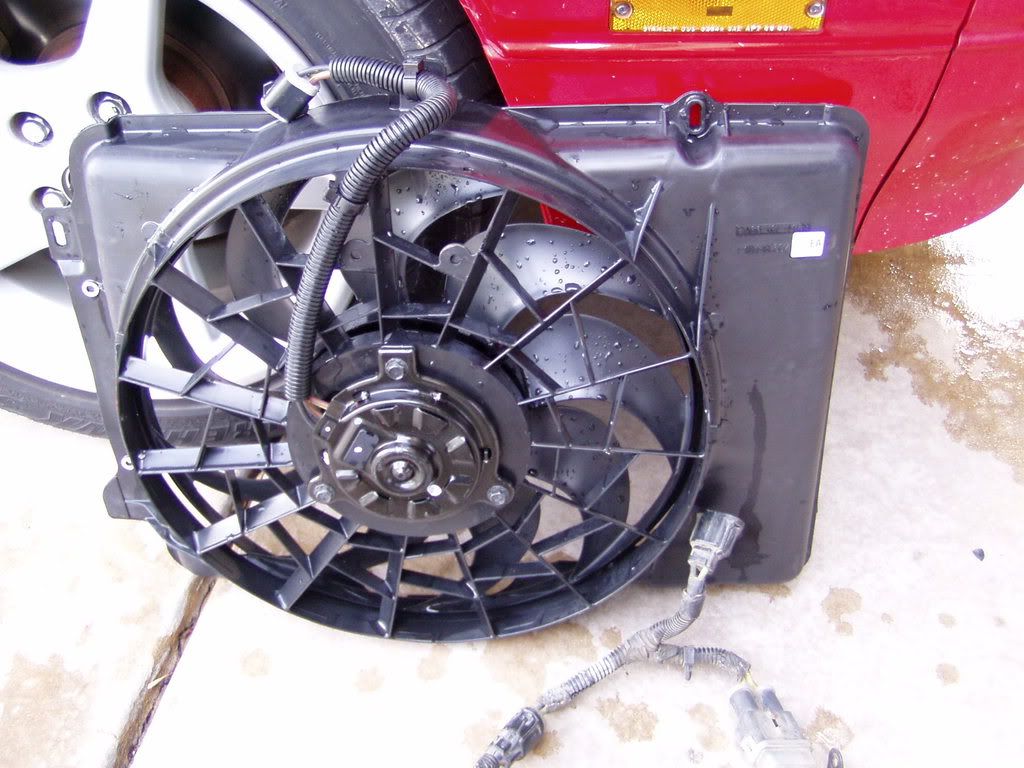
-A two speed Taurus efan.
Common as dirt, the two speed fan can be identified by the three wire connector.
-A SPST relay.
Your basic 4 (sometimes 5) pin automotive relay. Most modern cars have LOTS of these.
The one I used is a 40A unit from a Nissan (sorry, forgot the model) and was chosen because it had a convenient mounting tab, a connector and a fair amount of accessible wiring in good condition.
-A fuse and holder.
I'm using the 30A breaker assembly that was on the Taurus which donated it's fan.
I figured that if it was good enough for the original engineers, it'd work for me as well.
So far, over the past year, it has.
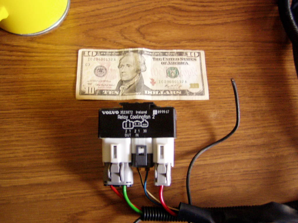
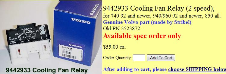
-Volvo 2-speed fan relay.
This unit, along with the dual-temp thermoswitch, is the heart of the project.
It integrates two relays and internal switchgear to toggle from low to high speed fan output.
Here's what it looks like...
Some specs and model info...
-Dual stage Audi/VW thermoswitch. NAPA part#- FS151, found on many 90's era "side rad" cars in the radiator's lower RH corner.It has three terminals marked "+", "1" and "2".
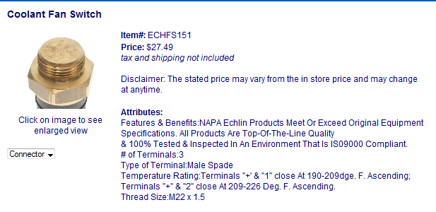
This switch poses the biggest obstacle to overcome during installation.
It's big- 22mm/1.5 thread- and simply won't fit in many of the preferred places (like the waterpump housing).
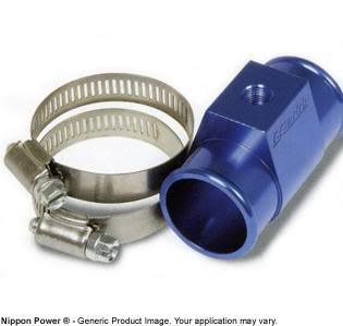
I'm using a rad hose adapter from AutoMeter which is intended to house a gauge sender but this required boring out and retapping the hole to accept the new switch. Since I didn't know anyone with such a large metric tap, I had to buy one. Fortunately, it was cheaper than I'd feared- only $18- and I figured it was worth the money.
I'll probably never use it again...
VW and Audi mount this switch on a bung in the rad endtank which would be a great location if you can have one fabbed in.
I have a replacement (all metal) stock rad and didn't feel it was worth the effort to mod it as I hope to replace the rad soon anyway.
Either way will work, so do as you will.
About the thermoswitch connector...
I was able to find 5 correct connectors in the junkyard in no time at all.
However...Audi apparently uses the switch as a ground point while VW must use it as a power point because the wire gauge is much different.
Audi uses very light gauge wire and they were all damaged to some extent (most had been spliced) while the VW part had heavier wire that was in good shape.
I'm using the VW connector just to have better wire to work with even though it's only carrying a ground signal.
Again, do as you will...the Audi connector- and wire gauge- will be fine if you can find one in good condition.
-A dog to oversee your work.

Sally deigned to pose for this pic but soon wandered off and was unavailble for further consultation.
Like many (most?) women, she does not consider working on cars to be fun or interesting.
Unlike most women though, she will pee on my tires which is either ironic canine commentary or a sign of poor bladder control (albeit suspiciously precise).
THE SCHEMATIC
I drew this diagram showing how all these parts interact...
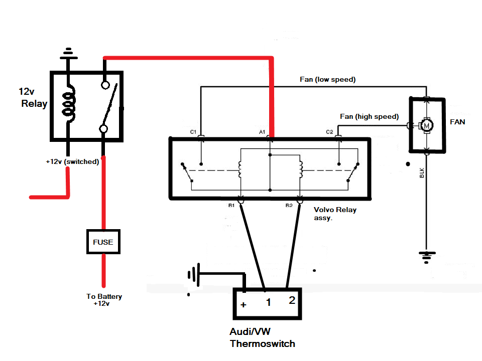
Basically, the single relay is used to feed power to the Volvo relay unit.
This relay is fed with a fused source direct from the battery and triggered by a switched 12v supply.
Alternatively, you could delete this relay and run a fused line from a battery source directly to the Volvo relay. This will leave the fan running- even when the car is turned off- until the thermoswitch cools below it's trigger point.
Many newer vehicles do have the run-on feature but I suspect they also incorporate timers to limit them, and I didn't need the extra complexity.
If someone wanted to research this further, please chime in.
Anyway...
The output from the SPST relay feeds the main power of the Volvo part.
From here, power is routed to either the low or high speed output and on to the fan itself.
The Volvo LOW/HIGH relays are triggered by a ground signal provided by the Audi/VW thermoswitch.
And that's it.
At 190�F the fan low speed kicks in and should the temp reach 204�F (which has never happened in my car) the Volvo relay will switch the fan from low to high speed.
All done automatically, with no driver input necessary- just the way Dearborn intended.
Installation
OK, we'll make this simple...the fan goes on the radiator.
How you achieve this is completely up to you- your skills, tooling and imagination are the only limits.
Ideally you want the fan mounted tightly to the rad core so all it's pulling power is directed through the core instead of sucking air from the engine bay (which, given it's druthers, it would much prefer to do).
Garage door sealing foam (from any big box store) is useful for sealing any gaps between the fan and the radiator and the rad and the frame.
In a perfect world, you would fabricate a custom shroud that completely- and tightly- fits the core and mount the Taurus fan (suitably modified) to this shroud.
Realistically, the Taurus assembly is a damn close fit to our stock rad and can be used as is.
I used the holes on the driver side of the Taurus fan flange to mount to the stock rad mounts and then the "push-pin" type fittings (common to many aftermarket efans) to fasten the other side.
Not ideal but as I said before, I plan on replacing the rad soon and will get more creative at that point.
At any rate, this setup has been on for nearly a year and works fine.
The rad hose adaptor/thermoswitch goes in the upper radiator hose.
(If you need more detailed instructions for this step, please walk away from the car and hire a mechanic)
The remaining three electrical components can go anywhere you want them.
I'll show how I did it but your car may/will offer different opportunities/options.
My two guiding criteria were to keep the wiring as short as possible and to use stock mounting points (i.e., I didn't want to be drilling holes anywhere).
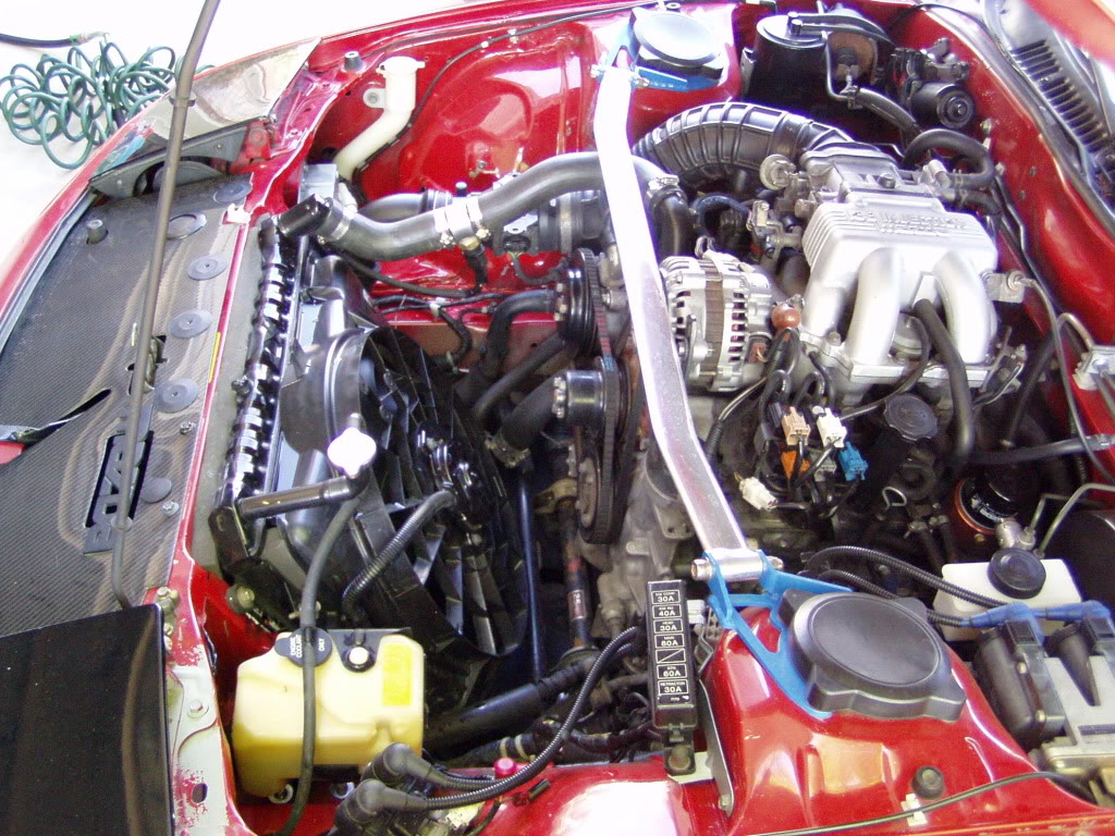
After a few contemplative hours of positioning/repositioning the components, here is the location I finally decided on...
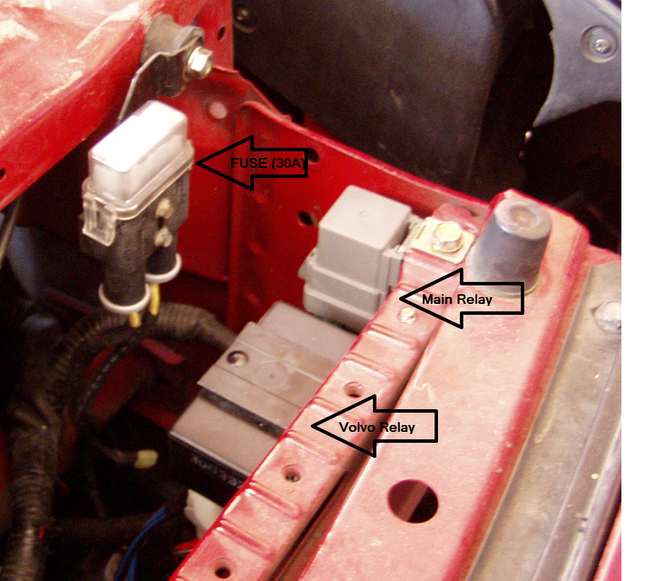
Mazda thoughtfully provided a multitude of threaded mount points and when the rad panel is installed, it's all completely stealthed.
This location also minimizes the amount of wiring visible in the bay.
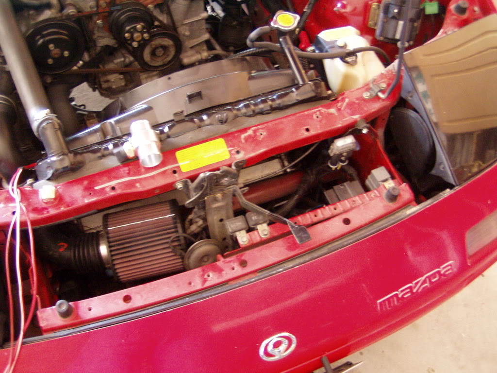
Here's a wider angle shot which better shows the area in relation to the engine bay...
If you're looking for a convenient source of +12v switched power, here it is...
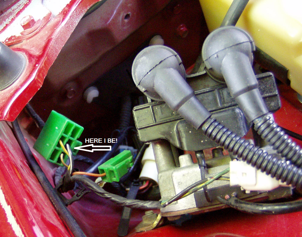
The B/W wire in the green diagnostic plug works fine and is right where I needed it.
And finally,the completed installation...
So, Does It Work?
So far, yes.
I tested the wiring for the whole setup by grounding the triggers and the fan does work on both speeds.
Started the car and low speed kicks in at 190�F, just as advertised.
Naturally, the temp immediately started to drop and the fan turned off, right @ 185�F or so.
It cycled this way till I shut her down.
At this point I can't say for certain that the high speed trigger works but I have every reason to believe that it does.
I also don't know yet how often or how long the fan will be on during my normal daily driving but I'll be keeping track as much as possible and will report any anomalies.
So there you have it.
Gotta go...I see Sally gazing speculatively at my tires.
There are a variety of reasons- some good, some not so much- for performing the swap but this writeup will assume that the decision has already been made and you're about to proceed.
There are a number of ways the fan can be wired- from the dead simple "always on" method to more sophisticated (and IMO, more acceptable) relay/thermoswitch setup.
I've been running the latter for nearly a year and have been very happy with the results but it's always bothered me that the "high speed" wasn't functional and the thermoswitch I used kicked in too early (@180�F).
Off and on I've been researching the issue, and between the internet and scouring the junkyard, I believe I've come up with a good solution.
By my definition, "good solution" means both fan speeds functional without driver intervention (i.e., manual switches), an OEM appearance and minimal wiring.
Fortunately, all this is possible using the components I've found and the cost was very reasonable- although this will depend on your luck in the junkyard.
I've tried to include as much info as possible about sourcing the parts, which should save you some time.
With but one exception (the thermoswitch) all my parts were used.
As for the install of the wiring components, this will depend greatly on the state of your engine bay.
I've relocated my battery to the passenger bin and deleted the AC and power steering, so there is a lot of open space and quite a few mounting points available.
You may need to be more creative if your bay is more original but the schematic will be the same in any case.
Since I've used OEM automotive parts, shock and water resistence should be fairly good and no special measures were taken to guard against them.
You'll need common hand tools to mount the components (again, the thermoswitch is the exception but I'll cover that later) and basic soldering skills/materials to complete the wiring.
There has been some discussion here lately regarding the suitability of soldering vs. crimping, and I've followed it with interest.
I've always been a "solder/heatshrink" adherent but may try the crimp method in the future.
You can teach old dogs new tricks, I guess.
At any rate, we're only extending a few wires so whichever method you prefer, have at it.
Finally, no matter how you source the components, I highly recommend visiting the junkyard to obtain the appropriate connectors.
Although there is nothing exotic about any of them, having the correct modular connector (and as much of the original wiring as possible) will make the install much cleaner and easier.This also makes future work nicer as all the parts are "plug-n-play" and you needn't refigure all the wiring every time it's disconnected.
WHAT YOU NEED
-A two speed Taurus efan.
Common as dirt, the two speed fan can be identified by the three wire connector.
-A SPST relay.
Your basic 4 (sometimes 5) pin automotive relay. Most modern cars have LOTS of these.
The one I used is a 40A unit from a Nissan (sorry, forgot the model) and was chosen because it had a convenient mounting tab, a connector and a fair amount of accessible wiring in good condition.
-A fuse and holder.
I'm using the 30A breaker assembly that was on the Taurus which donated it's fan.
I figured that if it was good enough for the original engineers, it'd work for me as well.
So far, over the past year, it has.
-Volvo 2-speed fan relay.
This unit, along with the dual-temp thermoswitch, is the heart of the project.
It integrates two relays and internal switchgear to toggle from low to high speed fan output.
Here's what it looks like...
Some specs and model info...
-Dual stage Audi/VW thermoswitch. NAPA part#- FS151, found on many 90's era "side rad" cars in the radiator's lower RH corner.It has three terminals marked "+", "1" and "2".
This switch poses the biggest obstacle to overcome during installation.
It's big- 22mm/1.5 thread- and simply won't fit in many of the preferred places (like the waterpump housing).
I'm using a rad hose adapter from AutoMeter which is intended to house a gauge sender but this required boring out and retapping the hole to accept the new switch. Since I didn't know anyone with such a large metric tap, I had to buy one. Fortunately, it was cheaper than I'd feared- only $18- and I figured it was worth the money.
I'll probably never use it again...
VW and Audi mount this switch on a bung in the rad endtank which would be a great location if you can have one fabbed in.
I have a replacement (all metal) stock rad and didn't feel it was worth the effort to mod it as I hope to replace the rad soon anyway.
Either way will work, so do as you will.
About the thermoswitch connector...
I was able to find 5 correct connectors in the junkyard in no time at all.
However...Audi apparently uses the switch as a ground point while VW must use it as a power point because the wire gauge is much different.
Audi uses very light gauge wire and they were all damaged to some extent (most had been spliced) while the VW part had heavier wire that was in good shape.
I'm using the VW connector just to have better wire to work with even though it's only carrying a ground signal.
Again, do as you will...the Audi connector- and wire gauge- will be fine if you can find one in good condition.
-A dog to oversee your work.
Sally deigned to pose for this pic but soon wandered off and was unavailble for further consultation.
Like many (most?) women, she does not consider working on cars to be fun or interesting.
Unlike most women though, she will pee on my tires which is either ironic canine commentary or a sign of poor bladder control (albeit suspiciously precise).
THE SCHEMATIC
I drew this diagram showing how all these parts interact...
Basically, the single relay is used to feed power to the Volvo relay unit.
This relay is fed with a fused source direct from the battery and triggered by a switched 12v supply.
Alternatively, you could delete this relay and run a fused line from a battery source directly to the Volvo relay. This will leave the fan running- even when the car is turned off- until the thermoswitch cools below it's trigger point.
Many newer vehicles do have the run-on feature but I suspect they also incorporate timers to limit them, and I didn't need the extra complexity.
If someone wanted to research this further, please chime in.
Anyway...
The output from the SPST relay feeds the main power of the Volvo part.
From here, power is routed to either the low or high speed output and on to the fan itself.
The Volvo LOW/HIGH relays are triggered by a ground signal provided by the Audi/VW thermoswitch.
And that's it.
At 190�F the fan low speed kicks in and should the temp reach 204�F (which has never happened in my car) the Volvo relay will switch the fan from low to high speed.
All done automatically, with no driver input necessary- just the way Dearborn intended.
Installation
OK, we'll make this simple...the fan goes on the radiator.
How you achieve this is completely up to you- your skills, tooling and imagination are the only limits.
Ideally you want the fan mounted tightly to the rad core so all it's pulling power is directed through the core instead of sucking air from the engine bay (which, given it's druthers, it would much prefer to do).
Garage door sealing foam (from any big box store) is useful for sealing any gaps between the fan and the radiator and the rad and the frame.
In a perfect world, you would fabricate a custom shroud that completely- and tightly- fits the core and mount the Taurus fan (suitably modified) to this shroud.
Realistically, the Taurus assembly is a damn close fit to our stock rad and can be used as is.
I used the holes on the driver side of the Taurus fan flange to mount to the stock rad mounts and then the "push-pin" type fittings (common to many aftermarket efans) to fasten the other side.
Not ideal but as I said before, I plan on replacing the rad soon and will get more creative at that point.
At any rate, this setup has been on for nearly a year and works fine.
The rad hose adaptor/thermoswitch goes in the upper radiator hose.
(If you need more detailed instructions for this step, please walk away from the car and hire a mechanic)
The remaining three electrical components can go anywhere you want them.
I'll show how I did it but your car may/will offer different opportunities/options.
My two guiding criteria were to keep the wiring as short as possible and to use stock mounting points (i.e., I didn't want to be drilling holes anywhere).
After a few contemplative hours of positioning/repositioning the components, here is the location I finally decided on...
Mazda thoughtfully provided a multitude of threaded mount points and when the rad panel is installed, it's all completely stealthed.
This location also minimizes the amount of wiring visible in the bay.
Here's a wider angle shot which better shows the area in relation to the engine bay...
If you're looking for a convenient source of +12v switched power, here it is...
The B/W wire in the green diagnostic plug works fine and is right where I needed it.
And finally,the completed installation...
So, Does It Work?
So far, yes.
I tested the wiring for the whole setup by grounding the triggers and the fan does work on both speeds.
Started the car and low speed kicks in at 190�F, just as advertised.
Naturally, the temp immediately started to drop and the fan turned off, right @ 185�F or so.
It cycled this way till I shut her down.
At this point I can't say for certain that the high speed trigger works but I have every reason to believe that it does.
I also don't know yet how often or how long the fan will be on during my normal daily driving but I'll be keeping track as much as possible and will report any anomalies.
So there you have it.
Gotta go...I see Sally gazing speculatively at my tires.


Trending Topics

 05-12-09, 05:05 PM
#11
Sally would like to "visit" your tires.
At least I think that's what "Woof" meant.
A note about the (my) install of the thermoswitch...
The VW/Audi switch has standard parallel thread, not tapered pipe thread.
It comes with and is intended to seal by means of an aluminum crush washer, basically just like the oil drain plug.
You'll note that my rad hose adapter is round and there is no flat surface for the switch to seal against.
I used thread sealant (automotive grade "GOOP") to try and get around this.
I thought it was fine but noticed a fine mist on the MAF that sits right next to the switch, so it obviously wasn't.
This morning I defied convention* and removed the switch and wrapped it with five layers of PTFE ("teflon tape") AND smeared GOOP on top of the tape.
60 miles later, it appears to be holding up but this is clearly a stopgap measure.
I need to find a hose fitting that has a large enough flat surface that I can use the washer.
I thought I'd hit the jackpot when I espied a SAAB in the junkyard with what looked like the very thing...the sensor hole was absolutely correct (what are the chances of that?) but the hose diameter was wrong- 1 3/8" instead of 1 1/2".
I don't think I'll find what I need in the junkyard, so it's off to search some catalogues.
Shall update if I get lucky or, if anyone knows of a suitable adapter, please let me know.
The part does not have to be threaded to 22mm (after all, I bought the bloody tap and I'm not afraid to use it!) but it does need a flat surface big enough to accept a washer of @1" OD.
*Experts say the tape won't work on anything but tapered threads and they are probably right, but don't tell my car yet.
05-13-09, 06:11 AM
#12
There have been a multitude of detail changes since this was written but the basics are still the same.
It's been nearly two years since this was first installed and I've had no problems at all with water or debris on the filter (and this is my daily driver, so she's seen a bit of everything, including some hellacious rainstorms on I-80).
05-13-09, 01:37 PM
#15
The VW/Audi switch attracted me because it integrated both temp points into one part and, much like the Volvo relay, that simplicity was part of the goal.
Obviously, the problem with the switch sealing didn't occur to me beforehand.
That said, my temp fix is holding up fine so far (another 75 miles today) and if I had to, I'll bet something like JB Weld would permanently solve the issue.
I have found a Greddy adapter unit that looks promising and am awaiting a response back from the seller about the size.
If that doesn't pan out, there are two other options I can explore but I don't feel any real pressure yet as I believe it'll be fine as is.
05-13-09, 01:47 PM
#16
Yes and yes, but...
The VW/Audi switch attracted me because it integrated both temp points into one part and, much like the Volvo relay, that simplicity was part of the goal.
Obviously, the problem with the switch sealing didn't occur to me beforehand.
That said, my temp fix is holding up fine so far (another 75 miles today) and if I had to, I'll bet something like JB Weld would permanently solve the issue.
I have found a Greddy adapter unit that looks promising and am awaiting a response back from the seller about the size.
If that doesn't pan out, there are two other options I can explore but I don't feel any real pressure yet as I believe it'll be fine as is.
-Simplify.
05-13-09, 02:06 PM
#17
I thought of something like that but really don't want to mess with the rad.
It's a fairly new, all metal replacement that's going to be sold off when I do the motor swap and I think it'll be easier if it's unmolested.
Since I've already cut the rad hose, I may as well keep going in that direction since neither the hose(s) or the adapter will carry over during the swap. I can have a bung installed on the new aluminum rad when I order it.
At this point, I have two other options...
-Turn an adapter out of billet, or
-Turn a bung and have it welded into the existing piece.
Clearly, I have a lathe, so neither of these are terribly difficult for me but I was trying to make this write up applicable to as many people as possible and I suspect most folks don't have machine tools.
05-13-09, 06:36 PM
#18
Opinions are like........
There are hose adapters that you can mount temp senders on. Look at the Saab 900's at the salvage yards. Should look something like attached picture spliced into the radiator hose. They can be drilled/tapped and adapted to almost any sender that'll fit.
05-13-09, 07:48 PM
#19
@deadRX7Conv...
The unit in your first thumbnail is the very one I'm using.
Available from Summit, and no doubt many other suppliers.
The second pic is a special adapter made for Honda engine swaps.
The third is the SAAB part.
Both of these last two are the wrong size for our rad hoses.
Here is the Greddy part I'm hoping will work...
I'm waiting to hear back about how big the flat area is.

 06-30-09, 03:20 PM
#21
No, not really.
My ghetto sealed thermoswitch/hose adaptor has been fine for the past 7 weeks and the system as a whole works perfectly.
Recently upgraded to a Godspeed radiator and briefly considered redrilling and tapping it's bleed screw orifice for the 22mm thermoswitch but decided to leave well enough alone.
Looked like it would work though.
Currently involved in my next junkyard fabulous mod, just scored the last major piece today.
The fun never ends.
07-07-09, 09:09 PM
#22
Additional info....
Turns out it's possible to trick the ECU into using the BAC valve to increase idle when the fan kicks on.
See this thread- post #18 for addition wiring instructions.
Turns out it's possible to trick the ECU into using the BAC valve to increase idle when the fan kicks on.
See this thread- post #18 for addition wiring instructions.
07-07-09, 11:40 PM
#24
They would be easier to mount but your wiring would be slightly more spread out (depending of course, on where you located them).
07-07-09, 11:47 PM
#25
As Jackchild noted, you could use two thermoswitches (probably standard 1/8 NPT) with different switchpoints to do the same thing as the large Audi part.
They would be easier to mount but your wiring would be slightly more spread out (depending of course, on where you located them).
They would be easier to mount but your wiring would be slightly more spread out (depending of course, on where you located them).
 mishimoto, so he bought a spal 1700cfm i put it in today