Aquamist HFS-5 system: Official Q&A...
 03-15-09, 10:40 AM
#126
Senior Member
Thread Starter

Join Date: Sep 2006
Location: uk
Posts: 402
Likes: 0
Received 0 Likes
on
0 Posts
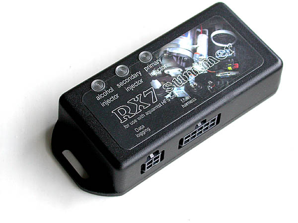
IDC summer update...
I have had many questions rescently regarding the "IDC-summer" module we designed for the RX7 communiity.
Will it work with other systems on the market? Many have asked.
The simple answer is "No" because I don't know of any system other than aquamist reads the IDC signal and use it as a prime source to meter WAI flow.
Some systems can take in a 0-5V signal to control the speed of a water pump. PPS (progressive) pump speed system. Unfortunately, due to lack of dymanic range (<2:1) and linearilty, it won't do justice to the wide dynamic range of the "IDC-summer", in excessive of 500:1 (from idle to peak power).
So I rework the original "IDC Summer" wiring configuration so that it can be used effectively with absolute precision and wide dynamic range - in stand-alone mode. Before jumping in, please note the system performance is greatly dependentable on the choice of pump and inline PWM valve.
So if anyone is interested in going further with this idea, do post questions here... I know a few has already started on this. Please do chime in and hoping we can make this "Forum-made" system to suit all, at a minimum of cost.
 03-15-09, 11:55 AM
#127
Like a lot of people I have read a bit about the summer but I don't know all the gory details about it.
The relay you have in the diagram: are you using a pressure switch to enable both the summer and the pump, and then the summer will control the actual flow? Could this proposed system be installed cleanly with zero boxes visible in the interior? I have enough crap in my interior and engine bay. I am going to install my AI system using the stock FC washer tank and mostly hide the wires and lines.
The relay you have in the diagram: are you using a pressure switch to enable both the summer and the pump, and then the summer will control the actual flow? Could this proposed system be installed cleanly with zero boxes visible in the interior? I have enough crap in my interior and engine bay. I am going to install my AI system using the stock FC washer tank and mostly hide the wires and lines.
03-15-09, 12:13 PM
#128
Bosozoomku
iTrader: (10)
Join Date: Oct 2008
Location: Seattle, WA
Posts: 632
Likes: 0
Received 0 Likes
on
0 Posts
Richard, this is precisely what I was hitting on in our PM discussion... Thanks for posting a clear visual reference!
This system is perfect for a "set it and forget it" type of set up used solely for keeping CCPs down and cleaning the CC. Come on at boost and match water delivery to fuel at 10-15% or however you prefer...
This system is perfect for a "set it and forget it" type of set up used solely for keeping CCPs down and cleaning the CC. Come on at boost and match water delivery to fuel at 10-15% or however you prefer...
03-15-09, 01:18 PM
#129
Senior Member
Thread Starter
Join Date: Sep 2006
Location: uk
Posts: 402
Likes: 0
Received 0 Likes
on
0 Posts
Like a lot of people I have read a bit about the summer but I don't know all the gory details about it.
The relay you have in the diagram: are you using a pressure switch to enable both the summer and the pump, and then the summer will control the actual flow? Could this proposed system be installed cleanly with zero boxes visible in the interior? I have enough crap in my interior and engine bay. I am going to install my AI system using the stock FC washer tank and mostly hide the wires and lines.
The relay you have in the diagram: are you using a pressure switch to enable both the summer and the pump, and then the summer will control the actual flow? Could this proposed system be installed cleanly with zero boxes visible in the interior? I have enough crap in my interior and engine bay. I am going to install my AI system using the stock FC washer tank and mostly hide the wires and lines.
The pressure switch will trigger the relay, inturn tuning on the "pump" and enabling the "summer" above a certain boost pressure.
The IDC-summer is doing the IDC conversion continuosly. When the blue wire is "ungrounded" by the relay, the inline valve starts to pulse and modulate the water flow - according to the summed value of the fuel injectors.
This makes a very simple WAI system with minimum of parts. The Summer box is not moisture-proof so you need to keep the "summer" in the grove compartment.
03-15-09, 01:24 PM
#130
Senior Member
Thread Starter
Join Date: Sep 2006
Location: uk
Posts: 402
Likes: 0
Received 0 Likes
on
0 Posts
Richard, this is precisely what I was hitting on in our PM discussion... Thanks for posting a clear visual reference!
This system is perfect for a "set it and forget it" type of set up used solely for keeping CCPs down and cleaning the CC. Come on at boost and match water delivery to fuel at 10-15% or however you prefer...
This system is perfect for a "set it and forget it" type of set up used solely for keeping CCPs down and cleaning the CC. Come on at boost and match water delivery to fuel at 10-15% or however you prefer...
There are a few minor details to improve the linearity of the system. Such as matching the flow with the inline's characteristics. I can help you on achieving your aim.
This system is capable of either altering the fuel/water ratio electronically or altering the nozzle size (mechanically).
03-15-09, 08:39 PM
#133
Racing Rotary Since 1983
iTrader: (6)

kudos to Richard and AQ for making a specific product for our turbo'd rotaries. i really like the concept of paralleling the IDC.
'probably one of the most accurate and certainly the most simple system i have seen.
a 21st century product in a market of too many 20th century systems.
howard
'probably one of the most accurate and certainly the most simple system i have seen.
a 21st century product in a market of too many 20th century systems.
howard
03-15-09, 09:07 PM
#134
Coolingmist S-HSV as they call it.
Their controller can run the valve from your summer's 0-5V signal triggered by boost but I figure its redundant so I will sell the controller to make up for the cost of the valve and instead I'm adding a boost switch as trigger. I'm going to miss their nice PC interface though.
The valve will be installed at the pump exit with a CV right before the tee to the dual nozzles. I don't like the idea of having the water line pressurized to 250psi all the time so I figure this way it only has 20 or so psi when not injecting.
Here is relevant info on the valve, I figure your summer can run it:
PWM Frequency 25 HZ to 15,000 HZ
Amp draw .49 AMPS
Voltage : 0 to 12 V DC
03-15-09, 09:41 PM
#135
Senior Member
Thread Starter
Join Date: Sep 2006
Location: uk
Posts: 402
Likes: 0
Received 0 Likes
on
0 Posts
Thank you for the information.
Just to confirm your proposed set up:
1. Coolingmist S-HSV 25Hz to 15,000Hz, 0 to 0.49AMPS or 0 to 12V
2. 250psi pump
3. PUMP ---> S-HSV ---> 20psi CV ---> Tee ---> dual nozzle.
We can supply the summer with the following PWM frequenies: 8000Hz, 400Hz, 50Hz and 20Hz. Default is 50Hz.
I want your system to work as well as it can be, please check the following for me:
4. What is the preferred PWM frequency for the S-HSV?
5. What is the ideal line pressure for the S-HSV to allow a linear flow response from the "Summer's" PWM output drive.
6. What is the opening duration of the S-HSV - I heard it is 1.5 mS - please confirm.
I have an idea, can you test run the S-HSV on your current controller on the 250psi pump. This way, I can confidently work with you to get the best out of the summer. You can do this by applying a 0 to 5V (wirh a variable trimmer potentiometer) input to the controller. Assemble the S-HSV and the pump. Let me know if you observe a linear response from the nozzle as you apply more voltage to the controller input.
That is all. Please do this as it is very important for the future of yoursetup.
03-16-09, 08:19 AM
#136
Just to confirm your proposed set up:
1. Coolingmist S-HSV 25Hz to 15,000Hz, 0 to 0.49AMPS or 0 to 12V
2. 250psi pump
3. PUMP ---> S-HSV ---> 20psi CV ---> Tee ---> dual nozzle.
1. Coolingmist S-HSV 25Hz to 15,000Hz, 0 to 0.49AMPS or 0 to 12V
2. 250psi pump
3. PUMP ---> S-HSV ---> 20psi CV ---> Tee ---> dual nozzle.
We can supply the summer with the following PWM frequenies: 8000Hz, 400Hz, 50Hz and 20Hz. Default is 50Hz.
I want your system to work as well as it can be, please check the following for me:
4. What is the preferred PWM frequency for the S-HSV?
5. What is the ideal line pressure for the S-HSV to allow a linear flow response from the "Summer's" PWM output drive.
6. What is the opening duration of the S-HSV - I heard it is 1.5 mS - please confirm.
4. What is the preferred PWM frequency for the S-HSV?
5. What is the ideal line pressure for the S-HSV to allow a linear flow response from the "Summer's" PWM output drive.
6. What is the opening duration of the S-HSV - I heard it is 1.5 mS - please confirm.
4. 400Hz with their controller, some users have run it with a Haltech standalone at 25Hz with good results. They also explained that it can be run non-pwm with a 0-5V driver requiring 5W at 5V to fully open.
5. 125-160psi, the pump I have is adjustable so I'll probably set it to 180psi or so since I'll have the 22psi cv in there. Or I can try how high it can go before it starts to leak.
6. 1.5ms response confirmed
I have an idea, can you test run the S-HSV on your current controller on the 250psi pump. This way, I can confidently work with you to get the best out of the summer. You can do this by applying a 0 to 5V (wirh a variable trimmer potentiometer) input to the controller. Assemble the S-HSV and the pump. Let me know if you observe a linear response from the nozzle as you apply more voltage to the controller input.
03-16-09, 06:03 PM
#137
Senior Member
Thread Starter
Join Date: Sep 2006
Location: uk
Posts: 402
Likes: 0
Received 0 Likes
on
0 Posts
Based on the valve specuifucation you have given above and confirmed. I should be able to work out a predicted dynamic range fairly accurately. The S-HSV appeared to be a perfect for this application.
I will do the calculation based on 50Hz, which is what your Summer is set to. In order to change frequency, you need to do some circuit board modifications. Are you reasonable at soldering?
Anyway, lets try 50Hz first. I will do it as soon as I can a moment.
I will do the calculation based on 50Hz, which is what your Summer is set to. In order to change frequency, you need to do some circuit board modifications. Are you reasonable at soldering?
Anyway, lets try 50Hz first. I will do it as soon as I can a moment.
03-22-09, 07:03 PM
#139
Senior Member
Thread Starter
Join Date: Sep 2006
Location: uk
Posts: 402
Likes: 0
Received 0 Likes
on
0 Posts
At 50Hz, each PWM cycle takes 20mS. The valve will response well from 1.5mS to 18.5mS. This translates to a dynamic range of 7.5% to 92.5%. The results is extremely impressive. You will get a linear flow between the red dotted line.
Here is the chart to verify the linear operating range. shaded area is the alcohol injected per PWM cycle.
03-25-09, 05:10 AM
#140
Senior Member
Thread Starter
Join Date: Sep 2006
Location: uk
Posts: 402
Likes: 0
Received 0 Likes
on
0 Posts
0-5V PWM converter
 03-25-09, 11:46 AM
#141
Ok trying to understand here... I thought these valves were full-on full-off and varied duty by varying frequency but I've learned that they work at a constant frequency so the question is, how do they vary duty? By varying orifice opening size?
Won't this in turn lower the pressure at the nozzle at low duty thus affecting atomization? Isn't this the same as varying the pressure at the pump (PPS)?
Keeping this in mind, what would be the optimal lowest duty recommended to keep the nozzle pressure at or above 40 or 50psi so that atomization is good?
03-25-09, 04:22 PM
#142
Senior Member
Thread Starter
Join Date: Sep 2006
Location: uk
Posts: 402
Likes: 0
Received 0 Likes
on
0 Posts
Ok trying to understand here... I thought these valves were full-on full-off and varied duty by varying frequency but I've learned that they work at a constant frequency so the question is, how do they vary duty? By varying orifice opening size?
Won't this in turn lower the pressure at the nozzle at low duty thus affecting atomization? Isn't this the same as varying the pressure at the pump (PPS)?
Keeping this in mind, what would be the optimal lowest duty recommended to keep the nozzle pressure at or above 40 or 50psi so that atomization is good?
Won't this in turn lower the pressure at the nozzle at low duty thus affecting atomization? Isn't this the same as varying the pressure at the pump (PPS)?
Keeping this in mind, what would be the optimal lowest duty recommended to keep the nozzle pressure at or above 40 or 50psi so that atomization is good?
A proportional valve will act as a PPS system, where low flow = low pressure, atomisation will be bad at low flow.
Lets assume it is a "proportional" valve, see if we can get it to work as a "PWM" valve.
Reading between the lines. Coolingmist claims the valve will open after 1.5mS after a 12V pulse is applied. This response time is better than any PWM valve I have ever seen. Let say the claim is true, your valve should behave exactly as I described on the last post.
My post above is based on a 50Hz fixed frequency or 20mS to cover each cycle. Every 20mS, you can have a new IDC% update, which is excellent. With this valve, you can control you flow linearly between an IDC of 7.5% to 92.5%. The dynamic range is 12.3x. Compared to a PPS system, at best you can only get 2x. So based on your specification you have given me, you will have an excellent dynamic range. Provided the valve meets the claimed specifications.
If it is difficult for you to test it without the correct equipment, I offered you this little 0-5V PWM to perform a quick test, all you need to do is apply 12V, wiring up the valve and water pump, you can instantly see the results as you twiddle the dial provided. (I will supply you with a dial potentiometer). I urge to take up this offer before the full installation, it will only a take a minute or two to wire up.
I do not want to get into the situation after a month of twos time, telling me the IDC Summer is not working as I claimed.
I will post a wiring diagram of this module if you like.
.
 03-28-09, 11:57 AM
#144
Senior Member
Thread Starter
Join Date: Sep 2006
Location: uk
Posts: 402
Likes: 0
Received 0 Likes
on
0 Posts
Ok trying to understand here... I thought these valves were full-on full-off and varied duty by varying frequency but I've learned that they work at a constant frequency so the question is, how do they vary duty? By varying orifice opening size?
Won't this in turn lower the pressure at the nozzle at low duty thus affecting atomization? Isn't this the same as varying the pressure at the pump (PPS)?
Keeping this in mind, what would be the optimal lowest duty recommended to keep the nozzle pressure at or above 40 or 50psi so that atomization is good?
Won't this in turn lower the pressure at the nozzle at low duty thus affecting atomization? Isn't this the same as varying the pressure at the pump (PPS)?
Keeping this in mind, what would be the optimal lowest duty recommended to keep the nozzle pressure at or above 40 or 50psi so that atomization is good?
 07-01-09, 05:15 PM
#145
DRIVE THE ROTARY SPORTS
iTrader: (5)
Join Date: May 2003
Location: CA (Bay Area)
Posts: 4,150
Likes: 0
Received 0 Likes
on
0 Posts
Can this be used with my haltech E11v2? I was under the impression that my Haltech could control the aquamist system, but I wasnt clear what was required to do this. This has probably been asked already, so sorry if I'm re-asking a previous question.
Thanks, Heath
Thanks, Heath
09-19-09, 12:41 PM
#146
Senior Member
Thread Starter
Join Date: Sep 2006
Location: uk
Posts: 402
Likes: 0
Received 0 Likes
on
0 Posts
The Haltech can control the aquamist HFS-5/6 system from a separate user channel.
The HFS-5 (1:1 idc tracking) has been replaced by the HFS-6, water/fuel flow can scaled by the user.
You just need to decide "Haltech controlled" (your own AI map) or follow the FIDC. The HFS-5/6 can be used for both.
 05-21-10, 11:33 PM
#149
Speed Mach Go Go Go
iTrader: (2)
Join Date: Oct 2001
Location: My 350Z Roadster kicks my RX7's butt
Posts: 4,772
Likes: 0
Received 2 Likes
on
2 Posts
I have had many questions rescently regarding the "IDC-summer" module we designed for the RX7 communiity.
Will it work with other systems on the market? Many have asked.
The simple answer is "No" because I don't know of any system other than aquamist reads the IDC signal and use it as a prime source to meter WAI flow.
Some systems can take in a 0-5V signal to control the speed of a water pump. PPS (progressive) pump speed system. Unfortunately, due to lack of dymanic range (<2:1) and linearilty, it won't do justice to the wide dynamic range of the "IDC-summer", in excessive of 500:1 (from idle to peak power).
So I rework the original "IDC Summer" wiring configuration so that it can be used effectively with absolute precision and wide dynamic range - in stand-alone mode. Before jumping in, please note the system performance is greatly dependentable on the choice of pump and inline PWM valve.
So if anyone is interested in going further with this idea, do post questions here... I know a few has already started on this. Please do chime in and hoping we can make this "Forum-made" system to suit all, at a minimum of cost.
 05-22-10, 03:30 AM
#150
Senior Member
Thread Starter
Join Date: Sep 2006
Location: uk
Posts: 402
Likes: 0
Received 0 Likes
on
0 Posts
This diagram is for a rotary specific application, stand-alone. It shows how a system can be put together using the Aquamist Rx7 summer module.
User has to go for a DIY route on this based on the summer module.
Richard
User has to go for a DIY route on this based on the summer module.
Richard

