2GCDFIS w/ TT (Transistor Trick) Write-Up (Simplified Design)
 11-20-05, 01:53 PM
#1
2GCDFIS w/ TT (Transistor Trick) Write-Up (Simplified Design)
2GCDFIS w/ TT (Transistor Trick) Write-Up
by Kent Abel and Tom Dowell
(gsl-se addict and teejs)
This is going to post a step-by-step write-up of the assembly of the basic TT circuit. This design works well, simple to build, and all parts are available locally. There is also a more advance auto-switching design. There are some people currently running auto-switching units that I have constructed in the past. We will then have circuit boards built for the more advance auto-switching units (works better in the high end than the basic unit) in the near future. Keep an eye on the transistor trick thread on the 1st gen section of www.rx7club.com for more details.
There have been a lot of requests from people who want to build the transistor trick for themselves. Well, here is how.
The parts listed are followed by RadioShack part numbers and price. Also look in local electronics shops or check with friends who are into electronics as RadioShack�s prices tend to be high. However, shipping a small order for a mail order electronics place just doesn�t make sense.
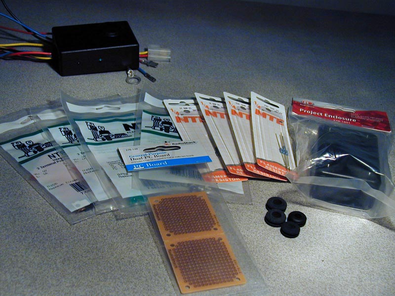
Parts List
(1) 7805 5 volt voltage regulator (276-1770 $1.59)
(4) 1k Ohm �-W resistors (271-1321 $0.99 for 5)
(1) 22k Ohm �-W resistors (271-1339 $0.99 for 5)
(1) 330 Ohm �-W resistors (271-1315 $0.99 for 5)
(2) 2N2222A NPN Transistor (276-2058 $0.69 each or 276-2009 $0.69 each or 276-1617 $2.59 for 15)
(1) T-1 or T-1� LED (green, red, or amber) (276-026 $1.29 for 2)
(1) 3�x2�x1� Project box (270-1801 $2.29)
(1) Perforated circuit board (276-148 $1.79 can be used for 2 circuits)
(1) Rubber grommet (64-3025 $1.99 for an assorted pack)
Selection of 18ga. Wire (for power, ground, signal, output, etc.)
Selection of connectors (male/female spade and bullet connectors)
Double sided foam tape to mount circuit in engine bay
Tools
Soldering iron (15W or 20W is a good size)
Solder (smallest diameter works well)
Drill
Xacto knife
Wire cutters, needle nose pliers, etc.
Total price for components is about $15 plus additional tools, wire, and misc connectors.
First take the perf board and snap it into its two components if you bought the RadioShack one listed. You will only need one portion. First off, you may notice that the board will not fit into the box. This is because the box has ridges on the inside to hold circuit boards vertically. You will need to either trim the ridges in the box or cut the board to fit. It is probably easiest to cut the board. Trim a bit at a time off the top and bottom using a hack saw, dremel tool, sander, Xacto knife, etc. I believe you will need to remove about 1/8� or so from each side. Just trim until the board fits.

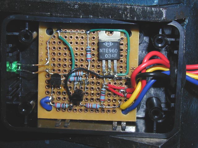
Next insert the two transistors near the center of the circuit board and the voltage regulator (7805) in the upper right-hand corner. For the voltage regulator (7805), you will need to bend the leads 90* downward (away from the side that has the numbering on it). I find that a pair of needle-nose pliers works well for this. Bend near where the lead transitions from being wide to being thin. Insert the voltage regulator into the perf board in the upper right-hand corner. The regulator should be laying flat with its marking facing up.
Next insert the resistor as shown in the following figure. Note the colored stripes on the body of the resistors. These indicate the value of resistance each one has. Insert the resistors so that their lead will be next to the part that they are connecting to. This will reduce or even eliminate the amount of additional wire connections that you will have to make.
Now for the LED. Bend the leads of the LED 90* and insert near the edge of the board. The LED does have a positive and negative orientation. If you put it in backwards, it will not work. The longer lead of the LED should be connected to 5v (green connection in above diagram).
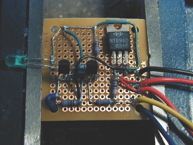
The layout now should look something like:


Use the long leads of the components to connect to reduce the number of wire connections as shown in the above pictures. The remaining connections are easiest made with 20 or 22 AWG solid strand wire. This is available at Radio Shack as well. You will only need a small amount. You may be able to find some place else that sells small wire like that for a cheaper price.
Once the components are in place, it is time to solder. Heat each connecting point for a few seconds and touch the solder to the joint. The solder will pull itself into the connection. I find that a small iron in the 15 to 20 watt range works well for this. Once all the connections are soldered, trim off the excess lead length using wire cutters.
For the LED, just temporally solder one lead and do not trim. You will need to adjust its position once the board is placed in the box.
The soldered board will look something like this:
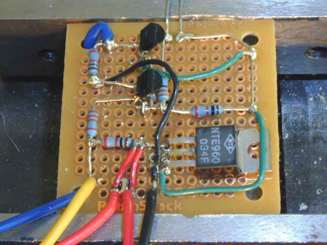
The colors shown on the output pads on the diagram below correspond to the wire colors used in the previous circuit builds. They are as follows:
- black (ground)
- red (12v, B terminal on J-109 ignitor)
- blue (output to 2nd gen coil)
- yellow (C terminal from J-109 {input signal})
The wires used to connect the circuit will be larger than the holes in the board. You will need to enlarge the 5 holes by using the tip of an Xacto knife or a small drill bit.
Insert wire next to the point that the wire will connect to and solder connections. Leave the wires 3 to 4 feet in length. You can trim them later once the circuit is installed.
Drill 1/8� hole in end of box for LED. Place the hole in the center. You can either measure it or just eye-balling it is fine.
Drill ~3/8� hole in the bottom of box (end opposite to the LED) and insert grommet. This is where the wires will exit/enter into the box. You may have to drill this hole in several steps as the plastic may crack. Maybe �, 5/16, than 3/8 will do the job. You can also drill a smaller hole (like �� and enlarge the hole with an Xacto knife.
Put the circuit board into the box and push the LED through the hole that you made. Run the wires through the grommet in the bottom of the box. Now that the LED is in position, you can now solder it and trim the excess lead length.
The final product should look something like:
Now it is time to install and test. Place one of the covers that came with the box. There is a black plastic one as well as an aluminum one. Choose the one you like best.
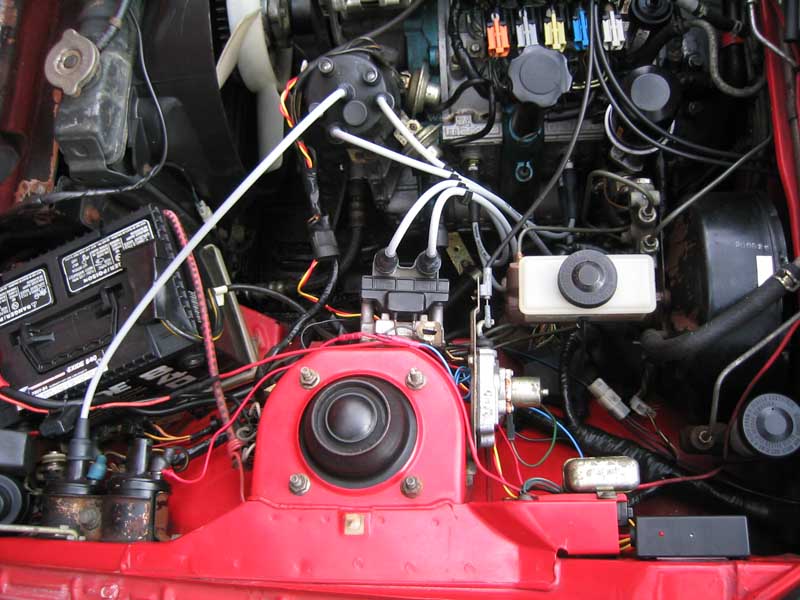
Installation:
Determine where you would like to mount the box. Either the front or back side of the driver�s side strut tower is a good choice.
Now try to find a place to mount the second generation coil. It is fairly large, so finding a good spot can be difficult. This is especially true on cars with A/C and P/S. If you don�t have A/C, the driver strut tower is a good spot. With A/C, you will need to move the A/C compressor all the way in (can�t use A/C) or remove the A/C completely if you want to mount on the strut tower. The other options are to either separate the coil from the ignitor to make the assembly thinner, or make a bracket to mount the coil to. Some good possible points to attach the bracket include the A/C bracket, near the relays on the inner fender, or maybe the engine itself.
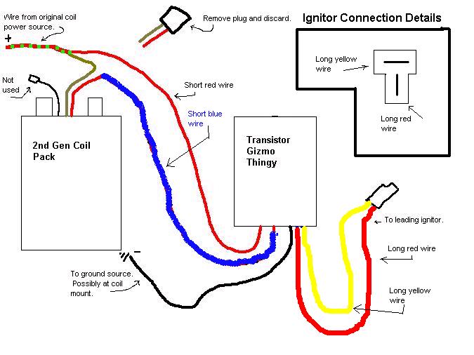
One red wire goes to a switched power source. The coil + of one of the stock coil is a convenient place. Trim wire to length and add a small ring terminal to connect to the coil +.
The black wire is ground. Connect to a convenient nearby grounding point. I used one of the mounting bolts that the 2nd gen coil uses. A 5/16� ring terminal works well for that case.
The other red and yellow wires connect to the first gen ignitor (J-109). The red goes to the B terminal and the yellow goes to the C terminal. It is best shown in the following diagram. You can use female spade connectors for this, but a better choice would be the stock plug. Try to get a plug off of a parts car or a wrecking yard so that you don�t have to cut your harness. Splice the wires from the connector to the red and yellow wires of the TT circuit. Solder and heat shrink tube the connections. This will give you a stock looking installation. It also gives the ability to easily switch back to stock if you ever need to. This is nice in the event of an ignition component failure. You can switch back to stock in a matter of minutes and be on your way.
These connections are very important to get right. If you connect the wires backwards to the first generation ignitor and try to start the car, you will kill your ignitor
Finally, the blue wire connects to the red wire on the second gen coil. This wire is the output of the circuit and the input to the coil/ignitor pack. I choose to cut off the stock white plug on the 2nd gen coil and use male/female bullet connectors instead. These give a secure connection, but are easy to remove and easy to replace in the future if ever needed.
Thanks, Kentetsu
Now that everything is connected. It is time to test. First, double check all your connections and make sure they are correct. Once that is checked, turn the key to the ON position. The LED of the circuit should light. Now try to start the car. When cranking or at idle, you will see the LED blinking. Above idle, it will look solid as it flashes so fast, the human eye can�t detect the flashing.
If the car starts, you will need to reset timing. This circuit has shown to retard timing 8* to 10*. Reset to factory or your desired timing. Now take the car for a spin and see what you think.
I noticed a definite increase in power and response as well as a smoother idle. Others have also noted an increase in gas mileage with this mod.
Install (TheLatinHeat)
Other tips:
- replace leading plugs with 2nd gen leading plugs. These are the surface discharge type. They are available from Shucks/Checker/Kragen for like $4.99 each.
- Move trailing connection on the distributor over to leading (T --> L, T1 --> L1, T2 --> L2)
- The 1st gen wires don�t reach well in the 2nd gen coil posts. Try to find wires where you can slide the boot up or use 2nd gen wires (they are pretty long, though)
Building tips from Tom:
- After snapping the board the next step would be to fit it before attaching any components, which is what I did and I'm glad I did. Next would be to FIT THE LAMP, which is one I did not do. I eyeballed it... I recommend giving it a pre-bend and temporarily soldering it ....just enough to hold it and using either calipers or even just a 'story stick' (a piece of cardboard or even a popsicle sized stick) and mark where it touches, transfer that to the outside and mark and drill to fit.
- #55 bit for component leads (for running two leads in one hole)
- 1/16 bit for the 18 gauge wire
- A cheap chrome jewelers screwdriver worked great to compress a wire already in the hole to help get more room for another item (I filed the tip to narrow it a bit).
- If an 18 gauge wire is to share a hole with a component....take the component out and insert the 18 g wire first.
- When trying to attach a stranded wire to a component: rather than wrap the wire around the leg drill out a convenient hole NEXT to the lead and strip enough wire to have the wire in the hole and wire exposed going over the lead.
- When I hook up the single-red wire I put a male-spade at the coil pack and then extend to the 1st gen coil power. At the 1st male-spade I just insert 2 wires, one from the box and the 2nd goes to the 1st gen coil supply. I also put a short wire on the 1st gen coil supply that has a medium round terminal end on the end that goes onto the 1st gen coil supply terminal and a insulated female on the other end (the insulated female in case it has to be retroed in an emergency it is still hot but shielded) This way it is really easy to retro fit. The other side of the 1st gen coil has a plastic female that I unplug (for some reason that must exist).The coil wire can be either left 'hanging' and tucked or glove-boxed.
Hope this explains it all. If you have any questions, be sure to ask.
Special thanks to Tom (teejs) for building the circuit and taking pics as well as some excellent suggestions.
Kent
by Kent Abel and Tom Dowell
(gsl-se addict and teejs)
This is going to post a step-by-step write-up of the assembly of the basic TT circuit. This design works well, simple to build, and all parts are available locally. There is also a more advance auto-switching design. There are some people currently running auto-switching units that I have constructed in the past. We will then have circuit boards built for the more advance auto-switching units (works better in the high end than the basic unit) in the near future. Keep an eye on the transistor trick thread on the 1st gen section of www.rx7club.com for more details.
There have been a lot of requests from people who want to build the transistor trick for themselves. Well, here is how.
The parts listed are followed by RadioShack part numbers and price. Also look in local electronics shops or check with friends who are into electronics as RadioShack�s prices tend to be high. However, shipping a small order for a mail order electronics place just doesn�t make sense.
Parts List
(1) 7805 5 volt voltage regulator (276-1770 $1.59)
(4) 1k Ohm �-W resistors (271-1321 $0.99 for 5)
(1) 22k Ohm �-W resistors (271-1339 $0.99 for 5)
(1) 330 Ohm �-W resistors (271-1315 $0.99 for 5)
(2) 2N2222A NPN Transistor (276-2058 $0.69 each or 276-2009 $0.69 each or 276-1617 $2.59 for 15)
(1) T-1 or T-1� LED (green, red, or amber) (276-026 $1.29 for 2)
(1) 3�x2�x1� Project box (270-1801 $2.29)
(1) Perforated circuit board (276-148 $1.79 can be used for 2 circuits)
(1) Rubber grommet (64-3025 $1.99 for an assorted pack)
Selection of 18ga. Wire (for power, ground, signal, output, etc.)
Selection of connectors (male/female spade and bullet connectors)
Double sided foam tape to mount circuit in engine bay
Tools
Soldering iron (15W or 20W is a good size)
Solder (smallest diameter works well)
Drill
Xacto knife
Wire cutters, needle nose pliers, etc.
Total price for components is about $15 plus additional tools, wire, and misc connectors.
First take the perf board and snap it into its two components if you bought the RadioShack one listed. You will only need one portion. First off, you may notice that the board will not fit into the box. This is because the box has ridges on the inside to hold circuit boards vertically. You will need to either trim the ridges in the box or cut the board to fit. It is probably easiest to cut the board. Trim a bit at a time off the top and bottom using a hack saw, dremel tool, sander, Xacto knife, etc. I believe you will need to remove about 1/8� or so from each side. Just trim until the board fits.
Next insert the two transistors near the center of the circuit board and the voltage regulator (7805) in the upper right-hand corner. For the voltage regulator (7805), you will need to bend the leads 90* downward (away from the side that has the numbering on it). I find that a pair of needle-nose pliers works well for this. Bend near where the lead transitions from being wide to being thin. Insert the voltage regulator into the perf board in the upper right-hand corner. The regulator should be laying flat with its marking facing up.
Next insert the resistor as shown in the following figure. Note the colored stripes on the body of the resistors. These indicate the value of resistance each one has. Insert the resistors so that their lead will be next to the part that they are connecting to. This will reduce or even eliminate the amount of additional wire connections that you will have to make.
Now for the LED. Bend the leads of the LED 90* and insert near the edge of the board. The LED does have a positive and negative orientation. If you put it in backwards, it will not work. The longer lead of the LED should be connected to 5v (green connection in above diagram).
The layout now should look something like:
Use the long leads of the components to connect to reduce the number of wire connections as shown in the above pictures. The remaining connections are easiest made with 20 or 22 AWG solid strand wire. This is available at Radio Shack as well. You will only need a small amount. You may be able to find some place else that sells small wire like that for a cheaper price.
Once the components are in place, it is time to solder. Heat each connecting point for a few seconds and touch the solder to the joint. The solder will pull itself into the connection. I find that a small iron in the 15 to 20 watt range works well for this. Once all the connections are soldered, trim off the excess lead length using wire cutters.
For the LED, just temporally solder one lead and do not trim. You will need to adjust its position once the board is placed in the box.
The soldered board will look something like this:
The colors shown on the output pads on the diagram below correspond to the wire colors used in the previous circuit builds. They are as follows:
- black (ground)
- red (12v, B terminal on J-109 ignitor)
- blue (output to 2nd gen coil)
- yellow (C terminal from J-109 {input signal})
The wires used to connect the circuit will be larger than the holes in the board. You will need to enlarge the 5 holes by using the tip of an Xacto knife or a small drill bit.
Insert wire next to the point that the wire will connect to and solder connections. Leave the wires 3 to 4 feet in length. You can trim them later once the circuit is installed.
Drill 1/8� hole in end of box for LED. Place the hole in the center. You can either measure it or just eye-balling it is fine.
Drill ~3/8� hole in the bottom of box (end opposite to the LED) and insert grommet. This is where the wires will exit/enter into the box. You may have to drill this hole in several steps as the plastic may crack. Maybe �, 5/16, than 3/8 will do the job. You can also drill a smaller hole (like �� and enlarge the hole with an Xacto knife.
Put the circuit board into the box and push the LED through the hole that you made. Run the wires through the grommet in the bottom of the box. Now that the LED is in position, you can now solder it and trim the excess lead length.
The final product should look something like:
Now it is time to install and test. Place one of the covers that came with the box. There is a black plastic one as well as an aluminum one. Choose the one you like best.
Installation:
Determine where you would like to mount the box. Either the front or back side of the driver�s side strut tower is a good choice.
Now try to find a place to mount the second generation coil. It is fairly large, so finding a good spot can be difficult. This is especially true on cars with A/C and P/S. If you don�t have A/C, the driver strut tower is a good spot. With A/C, you will need to move the A/C compressor all the way in (can�t use A/C) or remove the A/C completely if you want to mount on the strut tower. The other options are to either separate the coil from the ignitor to make the assembly thinner, or make a bracket to mount the coil to. Some good possible points to attach the bracket include the A/C bracket, near the relays on the inner fender, or maybe the engine itself.
One red wire goes to a switched power source. The coil + of one of the stock coil is a convenient place. Trim wire to length and add a small ring terminal to connect to the coil +.
The black wire is ground. Connect to a convenient nearby grounding point. I used one of the mounting bolts that the 2nd gen coil uses. A 5/16� ring terminal works well for that case.
The other red and yellow wires connect to the first gen ignitor (J-109). The red goes to the B terminal and the yellow goes to the C terminal. It is best shown in the following diagram. You can use female spade connectors for this, but a better choice would be the stock plug. Try to get a plug off of a parts car or a wrecking yard so that you don�t have to cut your harness. Splice the wires from the connector to the red and yellow wires of the TT circuit. Solder and heat shrink tube the connections. This will give you a stock looking installation. It also gives the ability to easily switch back to stock if you ever need to. This is nice in the event of an ignition component failure. You can switch back to stock in a matter of minutes and be on your way.
These connections are very important to get right. If you connect the wires backwards to the first generation ignitor and try to start the car, you will kill your ignitor
Finally, the blue wire connects to the red wire on the second gen coil. This wire is the output of the circuit and the input to the coil/ignitor pack. I choose to cut off the stock white plug on the 2nd gen coil and use male/female bullet connectors instead. These give a secure connection, but are easy to remove and easy to replace in the future if ever needed.
Thanks, Kentetsu
Now that everything is connected. It is time to test. First, double check all your connections and make sure they are correct. Once that is checked, turn the key to the ON position. The LED of the circuit should light. Now try to start the car. When cranking or at idle, you will see the LED blinking. Above idle, it will look solid as it flashes so fast, the human eye can�t detect the flashing.
If the car starts, you will need to reset timing. This circuit has shown to retard timing 8* to 10*. Reset to factory or your desired timing. Now take the car for a spin and see what you think.
I noticed a definite increase in power and response as well as a smoother idle. Others have also noted an increase in gas mileage with this mod.
Install (TheLatinHeat)
Other tips:
- replace leading plugs with 2nd gen leading plugs. These are the surface discharge type. They are available from Shucks/Checker/Kragen for like $4.99 each.
- Move trailing connection on the distributor over to leading (T --> L, T1 --> L1, T2 --> L2)
- The 1st gen wires don�t reach well in the 2nd gen coil posts. Try to find wires where you can slide the boot up or use 2nd gen wires (they are pretty long, though)
Building tips from Tom:
- After snapping the board the next step would be to fit it before attaching any components, which is what I did and I'm glad I did. Next would be to FIT THE LAMP, which is one I did not do. I eyeballed it... I recommend giving it a pre-bend and temporarily soldering it ....just enough to hold it and using either calipers or even just a 'story stick' (a piece of cardboard or even a popsicle sized stick) and mark where it touches, transfer that to the outside and mark and drill to fit.
- #55 bit for component leads (for running two leads in one hole)
- 1/16 bit for the 18 gauge wire
- A cheap chrome jewelers screwdriver worked great to compress a wire already in the hole to help get more room for another item (I filed the tip to narrow it a bit).
- If an 18 gauge wire is to share a hole with a component....take the component out and insert the 18 g wire first.
- When trying to attach a stranded wire to a component: rather than wrap the wire around the leg drill out a convenient hole NEXT to the lead and strip enough wire to have the wire in the hole and wire exposed going over the lead.
- When I hook up the single-red wire I put a male-spade at the coil pack and then extend to the 1st gen coil power. At the 1st male-spade I just insert 2 wires, one from the box and the 2nd goes to the 1st gen coil supply. I also put a short wire on the 1st gen coil supply that has a medium round terminal end on the end that goes onto the 1st gen coil supply terminal and a insulated female on the other end (the insulated female in case it has to be retroed in an emergency it is still hot but shielded) This way it is really easy to retro fit. The other side of the 1st gen coil has a plastic female that I unplug (for some reason that must exist).The coil wire can be either left 'hanging' and tucked or glove-boxed.
Hope this explains it all. If you have any questions, be sure to ask.
Special thanks to Tom (teejs) for building the circuit and taking pics as well as some excellent suggestions.
Kent
 11-21-05, 07:52 AM
#2
Waffles - hmmm good
iTrader: (1)
Kent,
Great writeup, its exactly what I've been needing as I start up this project. I think this post should go in the faq or the archive so we can all find it. This is a great winter project for anyone living where the weather keeps your rx7 idled. Thanks again.
Tim
Great writeup, its exactly what I've been needing as I start up this project. I think this post should go in the faq or the archive so we can all find it. This is a great winter project for anyone living where the weather keeps your rx7 idled. Thanks again.
Tim
The following users liked this post:
charliebars (01-14-24)
 11-21-05, 09:08 AM
#5
The Rotorheaded Geek
iTrader: (1)
Join Date: Mar 2002
Location: exit 8 in Manchester, NH
Posts: 920
Likes: 0
Received 0 Likes
on
0 Posts
How much is lost in the top end with this one for a car that will be on the street mostly? and What else is required to auto switch? Can I take the old design w/ a manual switch and put in an RPM switch instead? For what RPM?
11-21-05, 01:00 PM
#6
buzzzzz!-ook!-buzzzzz!

Join Date: Apr 2005
Location: Toronto/Can.
Posts: 354
Likes: 0
Received 0 Likes
on
0 Posts
just use the auto switching system.. its just an "or" gate, combining the output pulses of the FW and VW (stock output) systems.. effectivly both systems are on, and the or gate chooses the longer of the two (thats the simplified explanation).
i finally read the whole damn TT thread. w00t!
i finally read the whole damn TT thread. w00t!
Trending Topics
 11-22-05, 12:30 AM
#11
Lives on the Forum
aws140- The J-109 will tell the 2nd gen ignitor when to fire. The 2nd gen will now carry the load and fire the plugs, giving a hotter spark. The 1st gen ignitor is now retired to the point of simply supervising the system.
11-22-05, 12:45 AM
#12
Lives on the Forum
A lot of people are wondering what the differences are between the four systems (standard 2nd gen, TT fixed pulse, TT variable pulse, TT autoswitching), so I'll do my best to describe my experiences with them.
1. Standard: very nice upgrade giving smoother idle and cleaner exhaust. Good all around throttle response and performance.
2. TT fixed pulse: even better than standard, giving similar idle response and greatly improved top end power. Off idle response tends to feel a little "soft" with it, but not enough to stall out or cause any issues.
3. TT variable pulse: very strong off idle response, feels extremely crisp. Idle is very smooth but top end is about on par with standard mod (noticeably weaker than fixed pulsewidth).
4. Autoswitching TT: Simply put, the best of both worlds. However, the only real advantage that this has over running fixed pulse width is the crisper idle response. It's a nice upgrade, but if I couldn't have it and had to live with the fixed pulse I wouldn't shed any tears over it.
I hope this helps clarify some of the options for you guys.
Last edited by vipernicus42; 11-22-05 at 10:57 PM.
11-22-05, 03:49 PM
#14
Originally Posted by Kentetsu
aws140- The J-109 will tell the 2nd gen ignitor when to fire. The 2nd gen will now carry the load and fire the plugs, giving a hotter spark. The 1st gen ignitor is now retired to the point of simply supervising the system.
thanks so much. i figured that what it would be used for, but i just wanted to clarify.
11-25-05, 04:52 PM
#16
Glad you guys like. Thanks for the compliments. I think Kentetsu described the different setups well.
Jedon: This should work fine with a 3rd gen coil. I don't think anyone has tried it yet. It would be interesting to see if it was better than the 2nd gen coil or not.
Jedon: This should work fine with a 3rd gen coil. I don't think anyone has tried it yet. It would be interesting to see if it was better than the 2nd gen coil or not.
11-28-05, 02:42 PM
#18
Slave2TheFD
Join Date: Mar 2001
Location: Nevada City, CA
Posts: 658
Likes: 0
Received 0 Likes
on
0 Posts
gsl-se addict: Thanks! We'll give it a try.
Jeff20BL: Yes I have read that, but considering I have one sitting around, free is better than better on a pretty much stock 12a....
Jeff20BL: Yes I have read that, but considering I have one sitting around, free is better than better on a pretty much stock 12a....
11-29-05, 04:01 AM
#19
Jedon: Sounds good. Let us know how it works.
For those of you interested in the auto-switching version, in either a kit or assembled unit, with a professionally made Printed Circuit Board (PCB), we are compiling a list of intersested people to start a Group Buy here:
https://www.rx7club.com/group-buy-center-69/sa-fb-ignition-upgrade-transistor-trick-486305/
Thanks,
Kent
11-29-05, 06:59 PM
#20
Airflow is my life
OMG, you guys are awsome. I havent followed the development of Jeff20b's original idea of this. Now you've developed a DIY circuit? Man you guys rock! Ok can I lay out a couple of challenges since your wayyyyy smarter than me when it comes to this stuff?
1- Make a setup that would allow us to eliminate the trailing thru the cap? Direct fire with some kind of flip flop to switch coils?
2- Adapt this setup to work with a CAS?
No pressure.
Again, great work, thanks.
1- Make a setup that would allow us to eliminate the trailing thru the cap? Direct fire with some kind of flip flop to switch coils?
2- Adapt this setup to work with a CAS?
No pressure.
Again, great work, thanks.
11-30-05, 01:57 AM
#21
Oh come on, Carl. That thread is only like 28715567 pages long. Get reading!  j/k
j/k
Yes, we are going to have professional boards built, so that will make it easy to have either a DIY kit or a pre-built assembled unit. I built some of these before that people are now testing.
This write-up is for the simplified original circuit. This circuit works well, but isn't as advanced as the auto-switching version. This write-up was done to let others try out the "trick" to see how they like it and to hold them over until we get some boards built. I have to say the whole TT thing works quite well. I wouldn't have thought a stronger spark would make that much difference until I tried it. You should try it out too, Carl. I bet you'll like it.
The professional boards will give people a higher quality part, save me time etching/drilling, and that the fact it is the only way I can see really doing these with me being in Europe for 1 year.
Now for your challenges :
1. This was discussed a bit in the original thread. It hasn't been fully pursued, though. I think you could do it by adding a 2nd TT circuit with a few modifications. The trick is it has to know engine position since we need to switch between T1 and T2. This could be done adding a Hall effect sensor to either the main pulley or maybe the dizzy. The sensor would be say 30* before TDC. So, when the sensor passes, T1 is selected. After T1 fires, then T2 would get selected to fire next. The trick is what if the sensor misses the pick-up. You would need to setup something so that the trailing doesn't start firing 180* out of phase. Maybe circuitry to determine if a signal is missing or a false trigger and have the trailing shut off by default until the problem is corrected.
2. This would be hard to do without an ECU. You need to condition the signal from the VR sensors, but you then need to figure out advance. To do the advance you need to atleat know engine RPM and some way to determine load (MAP sensor, TPS). You would then need a circuit with a microcontroller to handle it. The best bet is to just use a MegaSquirt. They are pretty cheap, software is developed, and you can run just spark only if you still want to use a carb. They got the trailing figured out fairly recently, so you could use a CAS with 2nd gen leading and trailng coils with this setup.
Kent
j/kYes, we are going to have professional boards built, so that will make it easy to have either a DIY kit or a pre-built assembled unit. I built some of these before that people are now testing.
This write-up is for the simplified original circuit. This circuit works well, but isn't as advanced as the auto-switching version. This write-up was done to let others try out the "trick" to see how they like it and to hold them over until we get some boards built. I have to say the whole TT thing works quite well. I wouldn't have thought a stronger spark would make that much difference until I tried it. You should try it out too, Carl. I bet you'll like it.
The professional boards will give people a higher quality part, save me time etching/drilling, and that the fact it is the only way I can see really doing these with me being in Europe for 1 year.
Now for your challenges
:1. This was discussed a bit in the original thread. It hasn't been fully pursued, though. I think you could do it by adding a 2nd TT circuit with a few modifications. The trick is it has to know engine position since we need to switch between T1 and T2. This could be done adding a Hall effect sensor to either the main pulley or maybe the dizzy. The sensor would be say 30* before TDC. So, when the sensor passes, T1 is selected. After T1 fires, then T2 would get selected to fire next. The trick is what if the sensor misses the pick-up. You would need to setup something so that the trailing doesn't start firing 180* out of phase. Maybe circuitry to determine if a signal is missing or a false trigger and have the trailing shut off by default until the problem is corrected.
2. This would be hard to do without an ECU. You need to condition the signal from the VR sensors, but you then need to figure out advance. To do the advance you need to atleat know engine RPM and some way to determine load (MAP sensor, TPS). You would then need a circuit with a microcontroller to handle it. The best bet is to just use a MegaSquirt. They are pretty cheap, software is developed, and you can run just spark only if you still want to use a carb. They got the trailing figured out fairly recently, so you could use a CAS with 2nd gen leading and trailng coils with this setup.
Kent
12-01-05, 10:47 PM
#22
Full Member

Join Date: Oct 2005
Location: San Diego
Posts: 226
Likes: 0
Received 0 Likes
on
0 Posts
Originally Posted by Kentetsu
A lot of people are wondering what the differences are between the four systems (standard 2nd gen, TT fixed pulse, TT variable pulse, TT autoswitching), so I'll do my best to describe my experiences with them.
1. Standard: very nice upgrade giving smoother idle and cleaner exhaust. Good all around throttle response and performance.
2. TT fixed pulse: even better than standard, giving similar idle response and greatly improved top end power. Off idle response tends to feel a little "soft" with it, but not enough to stall out or cause any issues.
3. TT variable pulse: very strong off idle response, feels extremely crisp. Idle is very smooth but top end is about on par with standard mod (noticeably weaker than fixed pulsewidth).
4. Autoswitching TT: Simply put, the best of both worlds. However, the only real advantage that this has over running fixed pulse width is the crisper idle response. It's a nice upgrade, but if I couldn't have it and had to live with the fixed pulse I wouldn't shed any tears over it.
I hope this helps clarify some of the options for you guys.
1. Standard: very nice upgrade giving smoother idle and cleaner exhaust. Good all around throttle response and performance.
2. TT fixed pulse: even better than standard, giving similar idle response and greatly improved top end power. Off idle response tends to feel a little "soft" with it, but not enough to stall out or cause any issues.
3. TT variable pulse: very strong off idle response, feels extremely crisp. Idle is very smooth but top end is about on par with standard mod (noticeably weaker than fixed pulsewidth).
4. Autoswitching TT: Simply put, the best of both worlds. However, the only real advantage that this has over running fixed pulse width is the crisper idle response. It's a nice upgrade, but if I couldn't have it and had to live with the fixed pulse I wouldn't shed any tears over it.
I hope this helps clarify some of the options for you guys.
NOOB question:
Which of the 4 is discribed here?
Also the trailing ignitor is out on my '83, will I need to replace that before doing this add on?
I also need to by the coils, which ones do I need http://mazdatrix.com/ign-1.htm
Note: I will by them used off here of ebay
thanks
Last edited by mbaha; 12-01-05 at 10:55 PM.
12-02-05, 02:20 AM
#23
This write-up is for number 3 on that list. The group buy will be for number 4. The trailing doesn't matter much. You won't need the trailing fixed before doing this mod.
For the coil, you will need a 2nd gen leading coil w/ ignitor (The one shown as P on Mazdatrix). Usually they come this way (ignitor w/ coil). It can be off of any year 2nd gen ('86-'91) and can be off of either a TII car or an NA. It doesn't matter. E-bay or the 2nd gen for sale section on here are probably the best place to pick one up. You can also check with your local wrecking yards.
For the coil, you will need a 2nd gen leading coil w/ ignitor (The one shown as P on Mazdatrix). Usually they come this way (ignitor w/ coil). It can be off of any year 2nd gen ('86-'91) and can be off of either a TII car or an NA. It doesn't matter. E-bay or the 2nd gen for sale section on here are probably the best place to pick one up. You can also check with your local wrecking yards.