When you click on links to various merchants on this site and make a purchase, this can result in this site earning a commission. Affiliate programs and affiliations include, but are not limited to, the eBay Partner Network.
Attended the Haltech dealer training class this past Thursday and Friday and going in one of the key things I wanted to learn was closed loop boost control. Crispeed has been generous enough to put up his tutorial on a couple different boards and hopefully this info will help supplement that as well.
First thing we were told to do is run the car on the wastegate alone. Make a couple pulls and ensure that you have adequate control just on the gate. If there's something funky with the gate or whatever and boost oscillates wildly without a controller the Haltech is going to have a hard time giving good results.
Next you need to figure out what Start Duty Cycle you need. To do this you need to run the car in Open Loop mode. In open loop mode you simply program the duty cycle to create the desired boost level. The closer you can nail this duty cycle to your desired boost level the better off you'll be. If you're only doing one boost level you concentrate on that level. If you're doing boost by gear and have varying targets you need to find the duty cycle for each boost level you want to use. Once you have that info you can program the Start Duty Map with the proper values at the boost levels you're going to use and connect those points and linearize. Once you have the right duty cycle for that boost level you can go to the closed loop mode and go to work.
On the closed loop setup page enter the value from the open loop mode in the Start Duty Cycle box. If you're using boost by gear and have varying target just pick one of the targets and go with that info. The Start Duty Cycle will need to correspond to the value you have in the Closed Loop Target Map. Control Point Before Target should be set to about 3 psi. If you're only using one boost target leave the two check boxes below unchecked.
Now for the PID settings...
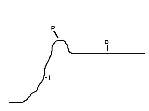
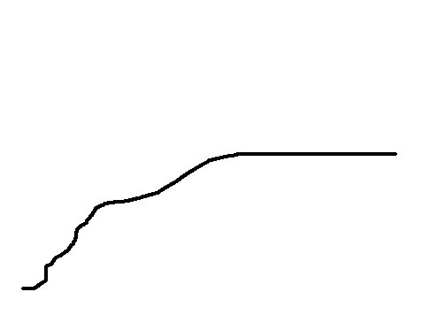
See the crude paint drawings below.
Each area of the boost response curve is labeled with the part of the PID structure that controls it. The thing to remember is that that all three are related and adjusting one usually effects the other. The easy one is the D - derivative. It is basically a sensitivity once the desired boost target it achieved. The default value of 0% should work. We were told you may move it to 1% for slightly tighter control
The I - integral is the rise rate of the boost. Too high and it's easy to overshoot the target. Too low and the boost is slow to reach the target like the 2nd picture above. We were told a good baseline setting for this value was 15%, or half of what the P value is.
The P - proportional controls the overshoot area of the boost curve and how it returns to steady boost. We were told a base value of 30% was a good place to start. Why Haltech says on the page to set them to 50-50-0 for default is a mystery. Basically think of the integral as boost rise and proportional as boost fall. Too much of one or the other and you get oscillations in boost around the target. Shoot for an integral value of 50% of the proportional value.
Looking at the first pic above you'll see that we've overshot the target before boost has settled to normal. In this case we can actually reduce the integral factor a few points to slow the rise time. That does slow boost response slightly. At this point adjusting the derivative is possible but can also lead to boost that oscillates and never settles at the desired level. Basically, you're trying to balance the integral and the derivative.
Looking at the second pic above the boost curve is very lazy in reaching our target. In this case the integral is too low and needs to come up a few points.
The key is getting the start duty cycle as close as possible. Once that is correct then the ECU has a much easier job of controlling boost around the target. Hope the above helps. This part of the class was certainly an eye opener.
The 'I' & 'P' from my experience have always ended up being much lower than what Haltech had suggest in the past.
It always depends on the application.
On one application 40, 40, 0 worked. On another 1, 1, 0 did the trick.
It boils down to trial and error.
What do you guys use for control point before target? I have found this makes a HUGE deal on how things work. If you control to soon on a slow rising boost (such as a 4th gear low rpm pull) your closed loop will spike because the closed loop is still trying to get to target boost (the duty cycle will raise up to try and get you to target boost because your cpbt was so far in front of when you actually reach target boost). If you set it to late like .5 or 0 psi before target it will not react fast enough for the 1st and 2nd gears. Any thoughts? I have tried 3 psi, but that seemed way to soon, and I had the problem above in higher gears. When you set it lower, it seems like it is more important and harder to "catch" the boost, and your start duty cycles need to be perfect.
Great write up, I have been trying to research the PID online for a while, but that seemed to not help me much. Like crispeed said it seems to be more of a trial and error.
I don't have a Haltech but I want to learn more about this. I am about to start tuning boost control on a factory Subaru ECU and they use a lot of the same principles. Does anyone have more info on control point before target or delay till boost control settings and how they relate to the PID coefficients?
It seems like a larger CPBD value and then a smaller integral number would allow the wastegate to stay shut as long as possible while still not spiking much. On external wastegates the poppet valve will open several psi before the rated spring pressure unless pressure is applied to the top port via the duty solenoid.
Also, does the solenoid run at 0% duty until control point before target is reached, and then duty rises to the start duty value?
I am posting on this one cause Chris is awesome plus his crude paint drawing identifies each PID and because it sort of looks like my closed loop boost log.
Some background on my setup. I have been using haltec's open loop boost control for a couple of years now. Attached is a snapshot of a open loop boost control and a closed loop boost control log. Running open loop, if I set the duty cyles to 29% (across the board on the open loop base duty map), I get a fairly consistent 12.5 psi on a WOT 2nd and 3rd gear pull.
On a closed loop boost control map, I set the start duty to 27%, PID to 0, Control Point Offset to 4, Delay till control .5, Target boost Map to 12.3 (all across), and Closed Loop Base Duty to 27 (all across). With this settings, I get an initial boost spike when going WOT in 2nd gear, and when shifting WOT to 3rd gear; however the boost droops right after the spike, and by drop I mean way below 12.XX psi.
Why is the boost dropping below 12.XX psi? Do I need to increase the D so that the boost drop does not falls below 12.XX psi?
Got a log showing actual duty and error? What are your PID settings currently?
I believe I have the DC on the same log, will verify when I get home (I do know that the open loop boost DC log shows a linear 29% DC). What do you mean by log showing error?
The easy one is the D - derivative. It is basically a sensitivity once the desired boost target it achieved. The default value of 0% should work. We were told you may move it to 1% for slightly tighter control
The I - integral is the rise rate of the boost. Too high and it's easy to overshoot the target. Too low and the boost is slow to reach the target like the 2nd picture above. We were told a good baseline setting for this value was 15%, or half of what the P value is.
The P - proportional controls the overshoot area of the boost curve and how it returns to steady boost. We were told a base value of 30% was a good place to start. Why Haltech says on the page to set them to 50-50-0 for default is a mystery. Basically think of the integral as boost rise and proportional as boost fall. Too much of one or the other and you get oscillations in boost around the target. Shoot for an integral value of 50% of the proportional value.
This right here. Finally a decent, thorough description of how a PID controller works in relation to closed loop boost control. Not that it is rocket science, or terribly hard to figure out I had a hard time when I first started learning how to use the PID controller for these things and never was fully sure of how the setting were intended to affect the result. Thanks. 100% rock solid clarification. Thank you.
First problem I see is that you are trying to run such a low duty cycle. Any valve will have a range where it effectively controls flow. Just like injectors don't have linear flow at low and high duty, the wastegate solenoid should be run between 30 and 80% duty. You're on the low end. I'd run a smaller gate spring so that you can use some more duty to hit your desired target.
Next, you'll never have good results with 0-0 for the P and I settings. Follow the procedure of increasing P until the boost oscillates and then bring in I to dampen the oscillations. It's a trail and error procedure. Just like fuel and ignition tuning, you need to creep up on the results.
Thanks for the info Chris, I disappeared from this thread because it seems that the boost drooping problem is not the specific to open/closed loop settings.
I have not been able to confirm, but it seems that my turbo is not able to hold boost after one or two boost runs. While working with the closed loop settings after posting on this thread, I was able to maintain boost while on closed loop during my first pass, attempted a second pass a minute or two after the first run and the data logs show the boost dropping.
I will be attempting to replicate the problem as time permits, and then work on resolving the issue. As of now, I am leaning towards not an open/closed loop setting problem; perhaps a solenoid, or dying turbo?
Hey I m posting here , didnt want to open a new thread with the same issue.
Im having trouble setting up the closed loop boost control, in the videos it all sounds understandable, but when Im on the track I cant figure out what is happening.
So this is a 4th gear pull with setting target boost to 40kpa or less:
So boost settles at around 50 kpa which is just the EFR soft wastegate spring
But when Im setting target boost to 80kpa Im only having 70kpa in 3rd gear, and having 100kpa in 4th and 5th:
PID settings I tried: 25-25-0 ;50-25-0 ; 50-25-20 it always looks the same, like its not even reacting to what Im doing.
I made the target boost being adjusted with the throttle, so when Im graduately accelerating from a corner in 3rd he is still stuck in the low base duty.
And when Im shifting up and hit the throttle fast, he picks the duty from 80kpa ( which I set too high so it overshoots I admitt)
Thats explanable, but then it doesnt get the boost controled within 4seconds...thats just ridiculous
How can I make it control boost faster?
Anyone have a clue ?
Otherwise Im going open loop, or external BC
-Patrick
Shoot me a PM or email (RGHTBrainDesign@Gmail.com) and I can get back to you in a week. Just need a log and the current ECU file and I'll do some changes for you to see if it's on the right track.
Ok thanks, you�ve got mail.
No need to hurry, the cars is not running rn, Im about to upgrade my intercooler system.
But hopefully I can hit the track again soon
 11-15-08, 08:25 AM


 plus his crude paint drawing identifies each PID and because it sort of looks like my closed loop boost log.