How to wire Line Lock / 2-Step
 12-10-13, 01:49 PM
#76
4th string e-armchair QB
Thread Starter
iTrader: (11)
Join Date: May 2005
Location: North Bay, Ontario
Posts: 2,745
Likes: 0
Received 0 Likes
on
0 Posts
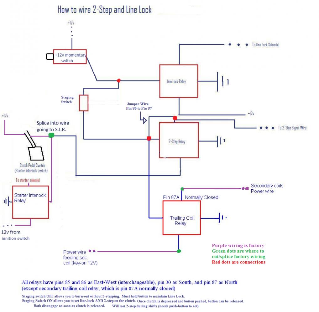
K just got another PM for some help with this. I made one last diagram without using the horn button and simplifying the clutch switch. For this to work make sure your clutch uses a +12V signal, otherwise you'll need to use a relay to make +12V on clutch depression. Hope this makes more sense, it's been a while since I've worked on my FC so let me know if this jives.
Also re-did the original using the horn button to activate the circuit:
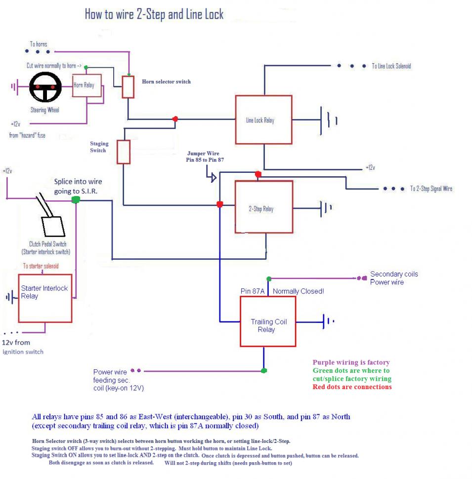
Also re-did the original using the horn button to activate the circuit:
 12-11-13, 08:26 PM
#77
What's the point??
iTrader: (6)
Join Date: Oct 2005
Location: Omaha, NE
Posts: 995
Likes: 0
Received 0 Likes
on
0 Posts
I use my cruise control clutch switch for launch control. Mainly because it is used for flatshifting too. gotta have a bit of time for the engine to lose revs when shifting.
12-23-13, 04:21 PM
#78
Full Member
iTrader: (6)
Join Date: Dec 2008
Location: Houston, Texas
Posts: 97
Likes: 0
Received 0 Likes
on
0 Posts
HELP!
I'm working on the wiring using the push button diagram and I have a couple of questions regarding the clutch switch (starter interlock switch).
The factory wires feeding the S.I.S. are, one blue/white which has 12v when key is turned.
the second wire is black/red, this wire receives the 12v once the S.I.S. pin closes the connection, then that allows the 12v to continue to feed the starter solenoid which starts car.
So I have every thing wired like the diagram and when I try to start the car I get nothing, but if I activate the 2 step switch and press button the car starts!!!
can someone help verify if the drawing is correct?
I cut the S.I.S. on the black/red wire side. I took the wire coming from the S.I.S. and ran wire to #86 pin on the relay, there is also the clutch signal wire on this pin that comes from the 2 step relay.
Pin #85 I have a ground
Pin #30 is to 12v ign. source
Pin #87 is the opposite end of the cut wire from S.I.S., this feeds the black/red
do I need to rearrange the order for one of these??
if I am looking at this correctly it seems that I could use a jumper wire from pin#86 to pin#87 ??
someone please help???
03-25-14, 01:00 AM
#80
4th string e-armchair QB
Thread Starter
iTrader: (11)
Join Date: May 2005
Location: North Bay, Ontario
Posts: 2,745
Likes: 0
Received 0 Likes
on
0 Posts
I PM'ed a mod a while back about changing the first post to reflect the last diagrams, they make a lot more sense...
Sorry I'm a little late. I don't follow what you're saying exactly, but all you need is to route +12V when the clutch is depressed (sounds like the black/red wire you mentioned?) as per diagram to pin 30 on the "2-step relay". Make sure to splice only though, so you don't disrupt the normal flow to the relay for your starter circuit.
Now as for the car starting when the push-button is engaged. YES. If you turn the key while you have the momentary switch pushed down (and the "staging switch" allowing flow through), the jumper wire that is keeping the "2-step relay" circuit open will allow the 12v push-switch to power the starter relay without the clutch. If the clutch is not powering the same relay to allow it to start, then you did something wrong, because that connection in green should be simply a splice/tee in the wiring. Nothing else in the Starter interlock circuits should be touched except for teeing into that +12V after pushing the clutch.
HELP!
I'm working on the wiring using the push button diagram and I have a couple of questions regarding the clutch switch (starter interlock switch).
The factory wires feeding the S.I.S. are, one blue/white which has 12v when key is turned.
the second wire is black/red, this wire receives the 12v once the S.I.S. pin closes the connection, then that allows the 12v to continue to feed the starter solenoid which starts car.
So I have every thing wired like the diagram and when I try to start the car I get nothing, but if I activate the 2 step switch and press button the car starts!!!
can someone help verify if the drawing is correct?
I cut the S.I.S. on the black/red wire side. I took the wire coming from the S.I.S. and ran wire to #86 pin on the relay, there is also the clutch signal wire on this pin that comes from the 2 step relay.
Pin #85 I have a ground
Pin #30 is to 12v ign. source
Pin #87 is the opposite end of the cut wire from S.I.S., this feeds the black/red
do I need to rearrange the order for one of these??
if I am looking at this correctly it seems that I could use a jumper wire from pin#86 to pin#87 ??
someone please help???
I'm working on the wiring using the push button diagram and I have a couple of questions regarding the clutch switch (starter interlock switch).
The factory wires feeding the S.I.S. are, one blue/white which has 12v when key is turned.
the second wire is black/red, this wire receives the 12v once the S.I.S. pin closes the connection, then that allows the 12v to continue to feed the starter solenoid which starts car.
So I have every thing wired like the diagram and when I try to start the car I get nothing, but if I activate the 2 step switch and press button the car starts!!!
can someone help verify if the drawing is correct?
I cut the S.I.S. on the black/red wire side. I took the wire coming from the S.I.S. and ran wire to #86 pin on the relay, there is also the clutch signal wire on this pin that comes from the 2 step relay.
Pin #85 I have a ground
Pin #30 is to 12v ign. source
Pin #87 is the opposite end of the cut wire from S.I.S., this feeds the black/red
do I need to rearrange the order for one of these??
if I am looking at this correctly it seems that I could use a jumper wire from pin#86 to pin#87 ??
someone please help???
Now as for the car starting when the push-button is engaged. YES. If you turn the key while you have the momentary switch pushed down (and the "staging switch" allowing flow through), the jumper wire that is keeping the "2-step relay" circuit open will allow the 12v push-switch to power the starter relay without the clutch. If the clutch is not powering the same relay to allow it to start, then you did something wrong, because that connection in green should be simply a splice/tee in the wiring. Nothing else in the Starter interlock circuits should be touched except for teeing into that +12V after pushing the clutch.
03-27-14, 09:02 PM
#82
Full Member
iTrader: (6)
Join Date: Dec 2008
Location: Houston, Texas
Posts: 97
Likes: 0
Received 0 Likes
on
0 Posts
I PM'ed a mod a while back about changing the first post to reflect the last diagrams, they make a lot more sense...
Sorry I'm a little late. I don't follow what you're saying exactly, but all you need is to route +12V when the clutch is depressed (sounds like the black/red wire you mentioned?) as per diagram to pin 30 on the "2-step relay". Make sure to splice only though, so you don't disrupt the normal flow to the relay for your starter circuit.
Now as for the car starting when the push-button is engaged. YES. If you turn the key while you have the momentary switch pushed down (and the "staging switch" allowing flow through), the jumper wire that is keeping the "2-step relay" circuit open will allow the 12v push-switch to power the starter relay without the clutch. If the clutch is not powering the same relay to allow it to start, then you did something wrong, because that connection in green should be simply a splice/tee in the wiring. Nothing else in the Starter interlock circuits should be touched except for teeing into that +12V after pushing the clutch.
the two step and line lock work great!
03-28-14, 02:33 PM
#87
Rotary Enthusiast
Join Date: Aug 2006
Location: Melbourne FL/San Antonio TX/Okinawa Japan
Posts: 1,216
Likes: 0
Received 10 Likes
on
10 Posts
My line look is on the rear brakes. So when I do a burn out no brake pressure goes to the rear brakes. This allows me to modulate the front brakes as the car goes through the water area. Makes doing a burn out smooth IMO. left foot brake.
03-28-14, 07:14 PM
#88
4th string e-armchair QB
Thread Starter
iTrader: (11)
Join Date: May 2005
Location: North Bay, Ontario
Posts: 2,745
Likes: 0
Received 0 Likes
on
0 Posts
With the linelock on the front brakes you can apply the lock and pre-load your driveline though. Kinda hard to do that without 3 feet when it's on the rears 
That was one of the points for me drawing these up anyways, to have the fronts release with the clutch so you can pre-load without creeping, and not have to time it or anything, just focus on the lights...
That was one of the points for me drawing these up anyways, to have the fronts release with the clutch so you can pre-load without creeping, and not have to time it or anything, just focus on the lights...

Thread
Thread Starter
Forum
Replies
Last Post
diabolical1
2nd Generation Specific (1986-1992)
30
01-30-16 05:50 AM