When you click on links to various merchants on this site and make a purchase, this can result in this site earning a commission. Affiliate programs and affiliations include, but are not limited to, the eBay Partner Network.
I'm figuring something out for my fuel system, but it's a been a bit confusing with all of these ORB ends on fuel rails and what not. The gist of it is that due to component placement, I'm trying to use a 90 degree adapter piece for clearance, but it's male, non-swivel ended on either side. How do you clock these things the right way around while it being sufficiently tight? Wait till o-ring contact and then clock to your desired orientation or does it need to be finger tight first?
Well, that's a bit problematic. Excuse my inexperience working with -AN fittings; this has been way over my head since I decided to switch fuel rails and then rework everything. I had no idea an ORB banjo even existed.
It's for a parallel rail setup on a REW-swapped FC. The feed runs along the firewall to a tee that splits the primary and secondary feeds. Off the end of the secondary side is an inline fuel pulsation damper and working the right angle between the FPD and tee is the issue. I'm making assumptions just from my eye-balling since I don't have some of the parts yet, but it looks tight. This is a general idea of what the arrangement will hopefully look like based on what you said:
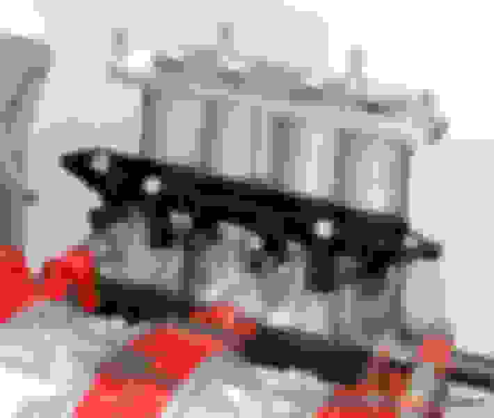
I'm hoping that once the parts arrive, it'll prove otherwise. The LIM is being switched out as well for an ERS one so I'm guessing the secondary rail gets scootched away from the firewall enough for the FPD. I'm going to borrow one of the pictures off MotoIQ since it's got an Xcessive LIM and an FFE rail, which should be very similar to what I'm doing:
I wouldn't use dead headed rails, but flow through instead.
Sorry, but could you explain to me some of these? I'm mostly modeling things off builds on here so I'm not well versed with the reasoning behind design choices when putting together a fuel system.
1. For the FPR, is the idea behind mounting it off the engine for its protection? Do engine vibrations affect its operation? I was under the impression that the closer the FPR was to the rails, the better... for... accuracy purposes or something. I've seen many builds with the FPR hung off the intake manifold so I didn't think it'd be an issue. So it should be off on the firewall or something? I'd have to orientate the whole feed-return the other way then.
2. Is the idea of not hanging the FPR or tee to protect the joints of the fittings? I can understand the FPR since it's fairly heavy. It's an Aeromotive A1000-6, but could that be remedied by a bracket supporting it from the rail mount? And as for the tee? They don't seem as heavy.
3. For the tee fitting, is it going to be an issue when splitting the fuel lines? It doesn't seem that much worse than a normal 90� bend for the primary rail. It seems no worse from a fluid dynamics perspective than the banjo you suggested. And for the secondary rail, it's a straight shot. Is there some some sort of water hammer effect of unnecessary turbulence I'm not considering? If so, I don't think it'd be too complicated to add a Y block...
4. Oh, and I think you mistook the fuel pulsation damper for the fuel pressure regulator. It's a flow through design with the fuel pressure regulator at the back. I'm away from my desk and thus anything to scribble with, but the gist of it is:
Feed hose -> splits (tee, y block, something) -> fuel pulsation damper on secondary rail side -> fuel rails -> fuel pressure regulator -> return hose
That being said, what's the issue with a dead head design? In effect, isn't that a return-less system?
Last edited by pzr2; 01-25-17 at 08:46 PM.
Reason: Typo
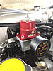
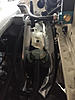
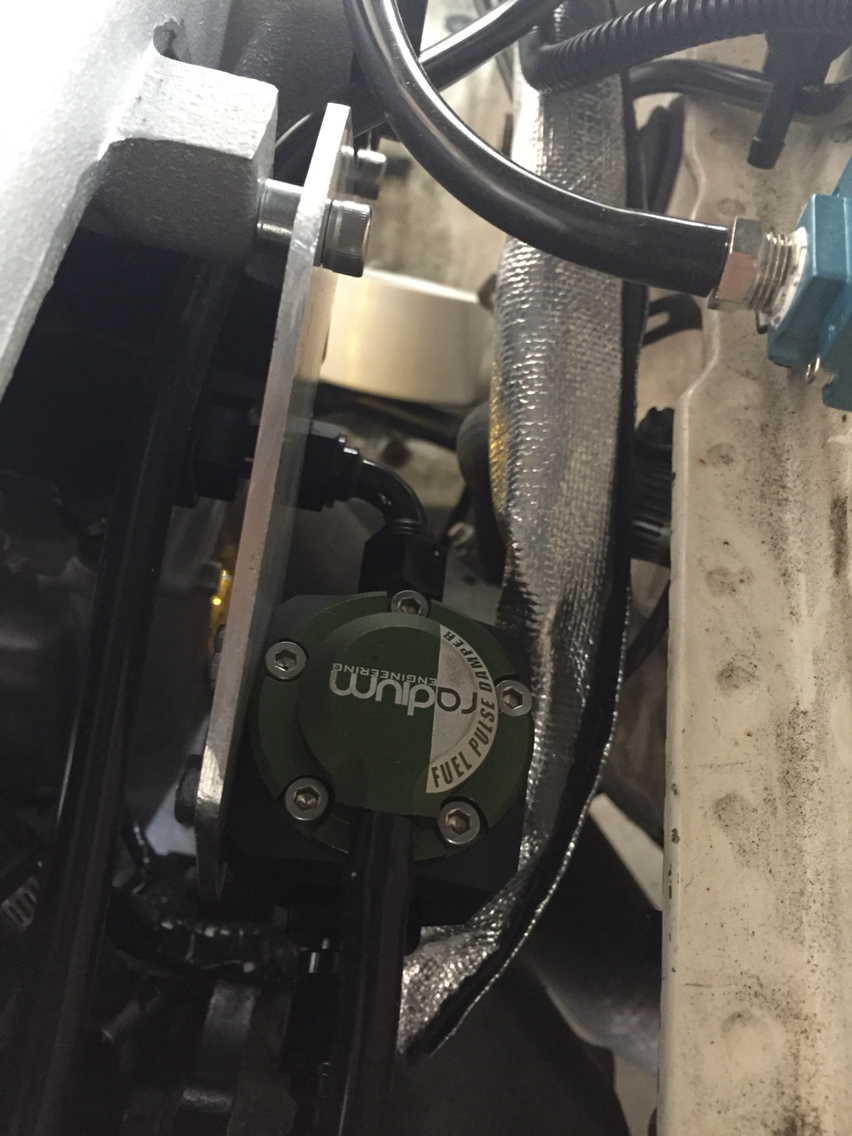
He's my location and support bracketing with a FPR and the Radium FPD.
FPR mounted to the front of the UIM, nothing new here.
Aluminum bracket bolted to the UIM to support the FPD. The FPD connects to the FFE rail with a 90* swivel. I don't like bolting anything to the chassis itself because of engine movement, unless there's sufficient slack in the lines.
@DC5Daniel, I take you're running a stock set of REW manifolds with the FFE rails? Is it possible to show a picture of the FPD's height relative the the firewall pinch seam? These pictures are immensely helpful by the way. How heavy is the FPD you have relative to your FPR, just as a rough guess?
@BLUE TII, have you ever had any issues with abrasion given the stainless braid and the extra service loops? Would you consider a bit of slack in a straight line sufficient, or are the loops necessary? My engine will be solidly mounted, but I'm aware there's still movement around the block from thermal expansion.
I never had a problem with abrasion where the loops are down on the engine.
I did have a problem with the SS hose on the driver's side of the fuel pressure regulator (on the firewall) where it rubbed an aluminum TPS bracket (on the engine) and wore a nice round notch into the aluminum.
I made a "figure 8" loop (which you can barely see if you look hard) to hold that SS hose close to the rubber heater core hose.
Ran like that for 15 years, but only ~50,000miles and no further problems.
@DC5Daniel, I take you're running a stock set of REW manifolds with the FFE rails? Is it possible to show a picture of the FPD's height relative the the firewall pinch seam? These pictures are immensely helpful by the way. How heavy is the FPD you have relative to your FPR, just as a rough guess?
@BLUE TII, have you ever had any issues with abrasion given the stainless braid and the extra service loops? Would you consider a bit of slack in a straight line sufficient, or are the loops necessary? My engine will be solidly mounted, but I'm aware there's still movement around the block from thermal expansion.
I'm actually one of those goobers with a hodgepodge of S4/5/6 parts, and a vented hood, so height and clearances will be different for me than you.
I would roughly say the FPD weighs about the same as the FPR, it's a heavy little guy. You don't need a huge bracket made of aluminum like I did, a bit overkill.
@ BLUE TII:
I see, that's kind of what I'm worried about. For the fuel system, I'm planning on running Earl's UltraPro 390 hose, which is sheathed in nylon braid instead of the typical stainless steel braid, so I'd actually be more worried about the hose being worn through instead of other engine components. If I'm interpreting the picture correctly, the loops are added in sections where the lines connect to something on the engine on one end and the chassis on the other?
@ DC5Daniel:
Oh, I see. I'm guessing an S4 block, S5 LIM, and S6 UIM? If it's an FC block, I'll take it as good data since my engine is mounted in the original FC location because I'm sticking to the original transmission. I'll probably err on the side of overkill since I've ordered the bigger XR model. It's shipping in on Thursday, so we'll see how it fits after the manifolds do as well.
Yes, the loops are where the hoses connect from engine component to chassis mounted component.
Loops do not necessarily need to be as large as I have them if your hose is more flexible than the SS hose I used.
If there is a point where you are worried about your hose being abraded you can cover the hose in expanding wire loom mesh or put ceramic/fiberglass tube with silicone sheath (fire-hose) over that section before you put the hose end on.
But not if it is going to be up against a sharp edge. Just re-route or hold the hose out of the way of any sharp edge.
If you want to be fancy you can make aluminum "L" brackets to hold the hose up off of the engine and use bulkhead fittings though the brackets, though this is one more fluid connection point that can fail.
Alternately, you can use a hard plastic material "L" to hold the hose up off the engine and clamp the hose to that.
It is possible to keep the hose from rubbing against anything if you want to be that careful.
 01-25-17, 02:11 PM