My 1991 RX7 Build...Ford 2.3T swap, with a little twist.
 09-25-15, 04:02 PM
#26
How do you plan on controlling the VGT?
I ran one of those turbos on a 13BT FC last year. It had some really strong points and really weak points, most of which were associated with the rotary engine.
The biggest obstacle was that a ported rotary likes a free flowing exhaust and a 70/60mm turbine wheel with, potentially, a teeny tiny A/R is bad.
All that rotary exhaust pressure also made it hard to control the VGT. I tried 4 different setups before I ditched that turbo.
I welded a nut to the lever arm for the VGT action and made a bracket that mounted to the original electronic actuator’s holes.
I tried several different air cylinders, all of which I bought at McMaster-Carr. Used a bushing and bolt to mount the top of the air cylinder to the bracket and a female rod end to bolt to the welded nut. It was a pretty crude design, but worked well, and the air cylinder end could be threaded in/out of the rod end to set just how small the static setting for the VGT.
Version 1 was a 1-1/16” bore. 1” stroke 2-port air cylinder. I connected both ports to a 2-way MAC solenoid and the common port to the intake manifold.
When I switched the solenoid, it’d allow either the top or bottom portion to see manifold pressure. This was great because at idle and high vaccum, the VGT would close and the car would be really quiet. The issue was that at WOT before positive pressure, there was no force to hold it shut and exhaust pressure would open the vanes.
Version 2 involved a 1-1/16” single port spring-return air cylinder. The spring didn’t do ****.
Version 3 was a 1.5” single port spring-return air cylinder. More effective, but exhaust would still push it open.
Version 4 was the 1.5” single port spring-return air cylinder with a check valve facing AWAY from the valve, so that it would hold a vacuum. This effectively just increased the spring pressure and helped a bit. I put a solenoid valve between the check and the air cylinder and used the ECU to turn it on/off. This allowed the vacuum to be bled off to help open the cylinder once under boost.
Honestly, I could never get it to hold shut. It always felt like a huge exhaust restriction. I actually blew off the 1/8” EGR block off plate because the back pressures were so high! Again, I know pinto motors don’t run large turbo hotsides, so YMMV.
PM me if you have questions and good luck.
 09-25-15, 05:57 PM
#27
Full Member
Thread Starter

Join Date: Aug 2015
Location: Columbia TN
Posts: 86
Likes: 0
Received 0 Likes
on
0 Posts
Well, obviously I have no room for the controller box(which would be the easy way since they make standalone controllers for the thing now). With my space constraints my options include a pneumatic actuator(though it sounds like you had bad results...I am surprised you didnt ditch the air cylinder idea earlier), or an electric linear actuator. I plan on trying a linear electric stepper motor first...coming forward and mounted to the compressor housing. Stepper motors are easy to control with megasquirt, the main problem will be tuning...megasquirt is setup for speed density...but thats worthless when the pressure remains the same bu the volume changes...very hard or impossible to tune with speed density and a VGT turbo. I will have to convert to a MAF sensor setup. It seems to me the best way to control this thing is a linear stepper motor of some type...that way while not moving it holds itself in position...whether thats open or closed. Worst case scenario I will simply use a threaded rod and set it up as different sized turbos with different positions and make a tune for each one...at least that way I can have a daily driver setting of say 8cm and a race setting of 14cm...and switch between them in 5 minutes. How did the the spool on a 1.3l btw? It seems like it would take forever even at 8cm
09-25-15, 07:39 PM
#28
I made 12psi at 3krpm in 4th. It spooled a good bit faster than my GT40R with dbb. If I set it really tight, I could get surge at really low RPMS. The drivability at the very small settings was huge. I would have to retune all my low load maps if I adjusted the VGT tighter. Megasquirt can run MAF no probem. You just need to know the 0-5V of the sensor you're using. You can also run a hybrid MAF/MAP tuning I believe. The ultimate reason I ditched the VGT, as fun of an experiment as it was, was because it cracked my manifold...in half.
Be careful with the electronics. The factory stuff was watercooled for good reason. Everything that touches the CHRA gets uncomfortably hot.
Be careful with the electronics. The factory stuff was watercooled for good reason. Everything that touches the CHRA gets uncomfortably hot.
09-25-15, 10:28 PM
#29
Full Member
Thread Starter
Join Date: Aug 2015
Location: Columbia TN
Posts: 86
Likes: 0
Received 0 Likes
on
0 Posts
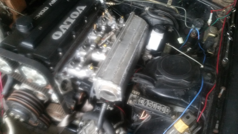
well, the only part that will touch the CHRA will be the adjusting rod, and the center section will still be water cooled, so with luck it wont be too bad...I expect temps to get to about 200 degrees or so on the rod...maybe I can find some type of phenolic hardware to attach it to the stepper motor, anyway, another reason I want MAF is the intake side of the equation...I am running BMW ITBs, and they seem to work better under MAF than they do Alpha-N or speed density. Speaking of which...I finally got the ITBs correctly mounted tonight
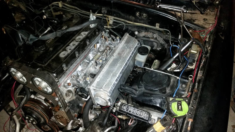
I consider this a huge victory....it will all fit under the hood. I did have to swap to a Miata brake booster though...I will see how the brakes feel and if I dont like them, I will change to a smaller master cylinder.

I consider this a huge victory....it will all fit under the hood. I did have to swap to a Miata brake booster though...I will see how the brakes feel and if I dont like them, I will change to a smaller master cylinder.
09-27-15, 06:25 PM
#30
Full Member
Thread Starter
Join Date: Aug 2015
Location: Columbia TN
Posts: 86
Likes: 0
Received 0 Likes
on
0 Posts


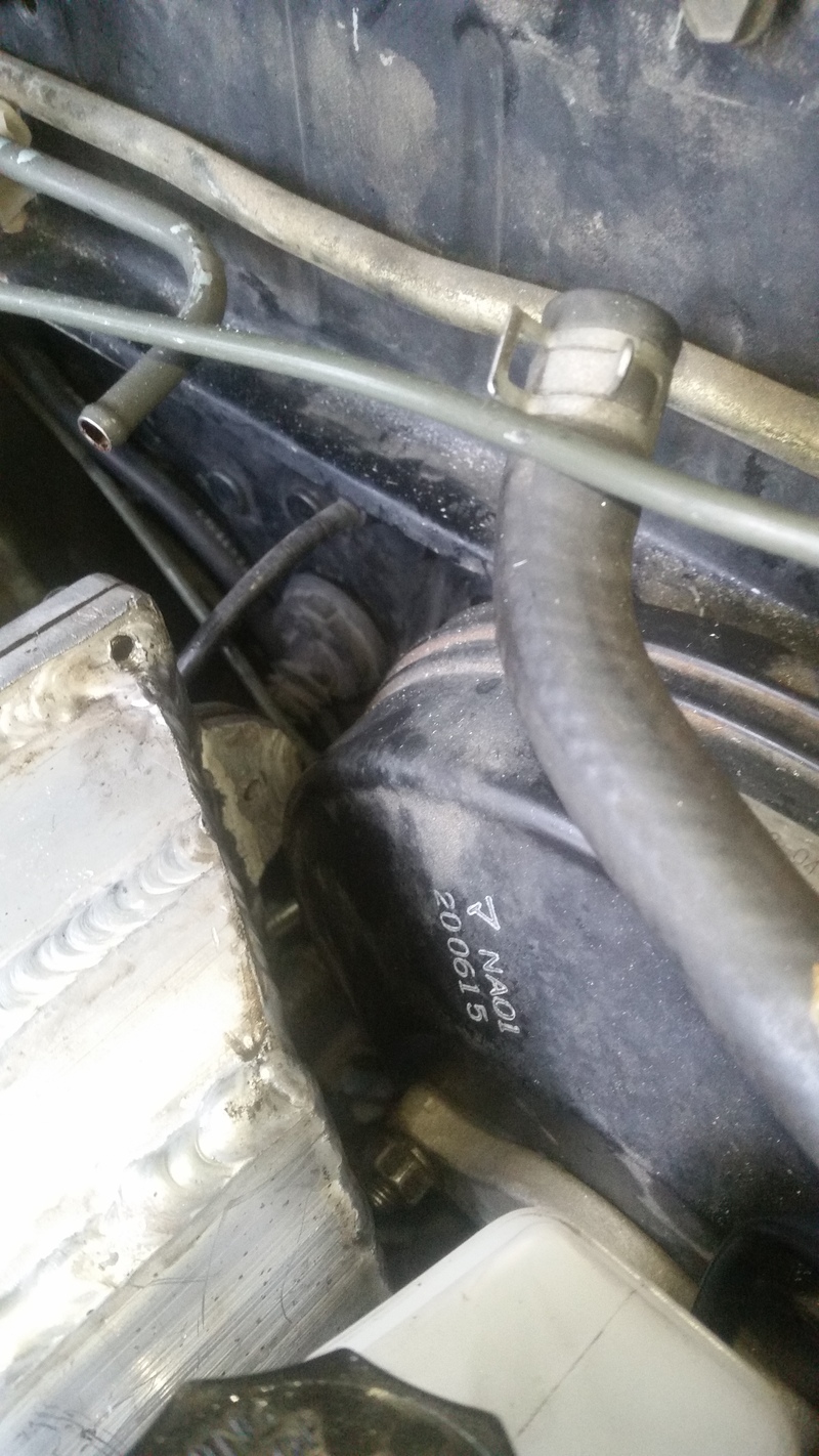
Another victory! While this 4 cylinder takes up every available inch of space under the FC hood, it does indeed fit. The turbo II hood closes over the engine with inches to spare(after trimming). Inches which I will put to good use by using them to mount the LS coils on the valve cover.
10-04-15, 05:05 PM
#31
Full Member
Thread Starter
Join Date: Aug 2015
Location: Columbia TN
Posts: 86
Likes: 0
Received 0 Likes
on
0 Posts
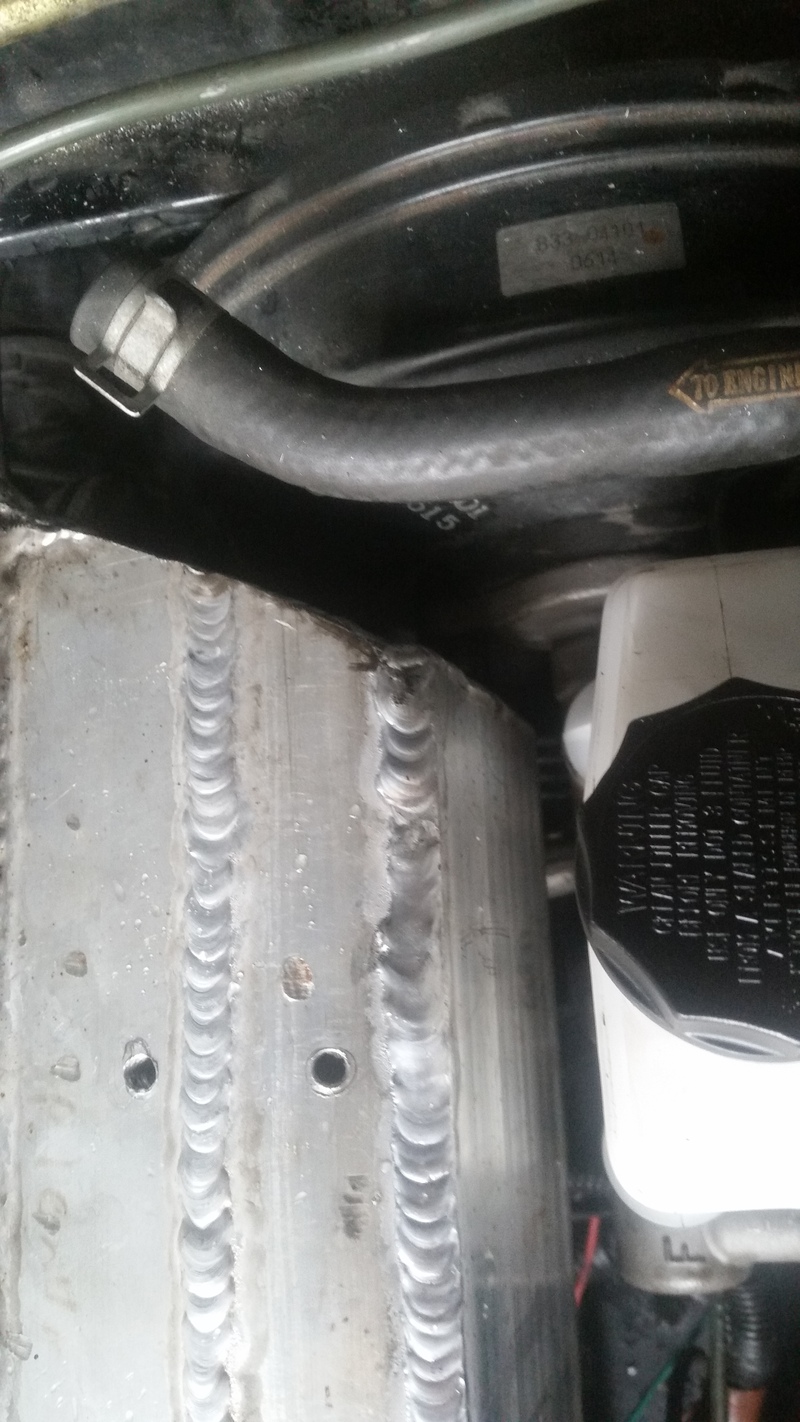
Well, today I spent working on porting the ITB to flange area...didnt take any pics...looks like any other porting you see, I just had to smooth the transition areas, etc. I also took a few minutes to mount my new Mazda B2200 Master cylinder...virtually identical to stock...its 7/8 as well, but its made of aluminum and the ports are on the driver side so it clears my plenum much better...it also helps I was able to flip the resevoir and gain more room there too...still not much room, but enough.


 10-18-15, 04:48 PM
#35
Full Member
Thread Starter
Join Date: Aug 2015
Location: Columbia TN
Posts: 86
Likes: 0
Received 0 Likes
on
0 Posts
Well, today I decided it was time to fabricate a trans crossmember, since for whatever reason the one I got from Granny's didn't even come close to fitting.
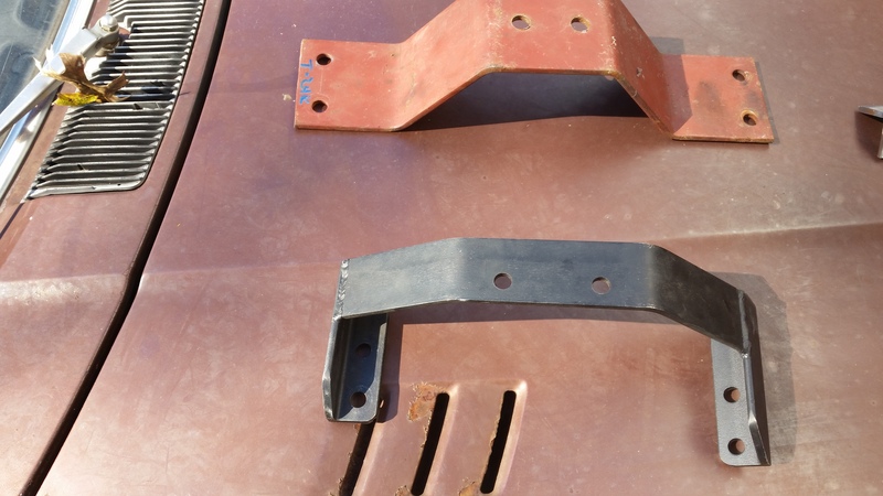
On the top is a t5 crossmember I had laying around for my XR4Ti, on the bottom is Granny's RX7 t5 swap crossmember, neither of these came close to working, so I had to fab my own.
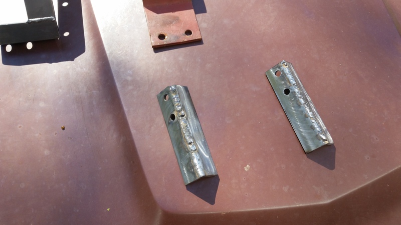
I hate it when I cant seem to find any of the angle Iron I know I have laying around...so I fabbed these out of flat bar stock, they form the base of the crossmember
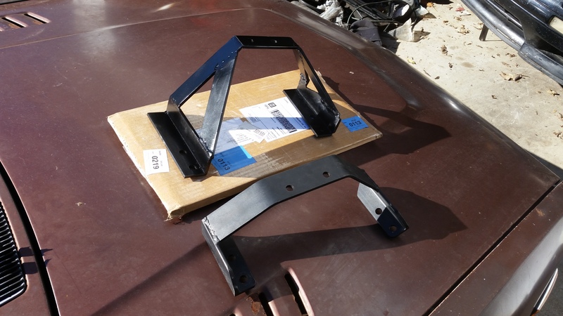
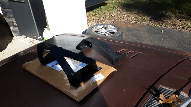
Here is the completed crossmember. I redesigned it a bit. I added gussets for strength. I flipped the angle around on the passenger side for more exhaust clearance(not that it was a problem before...but why not?) and the triangular area in the gusset on the driver side I opened up a bit since it lines up right where the speedo cable comes out of the trans.
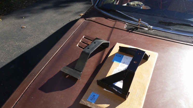
As you can see, for whatever reason the Granny's crossmember didnt come close to fitting. on my chasis for whatever reason both body mounting points are flat, even though they are different heights, not so on the Granny's crossmember. I dont think this is a problem with the Granny's piece since other people have used it without issue. I think the S5 chassis is different, or that I just got a freak car with weird mounting points, its hard to tell since I dont have the original trans crossmember that came out of it.

On the top is a t5 crossmember I had laying around for my XR4Ti, on the bottom is Granny's RX7 t5 swap crossmember, neither of these came close to working, so I had to fab my own.

I hate it when I cant seem to find any of the angle Iron I know I have laying around...so I fabbed these out of flat bar stock, they form the base of the crossmember


Here is the completed crossmember. I redesigned it a bit. I added gussets for strength. I flipped the angle around on the passenger side for more exhaust clearance(not that it was a problem before...but why not?) and the triangular area in the gusset on the driver side I opened up a bit since it lines up right where the speedo cable comes out of the trans.
As you can see, for whatever reason the Granny's crossmember didnt come close to fitting. on my chasis for whatever reason both body mounting points are flat, even though they are different heights, not so on the Granny's crossmember. I dont think this is a problem with the Granny's piece since other people have used it without issue. I think the S5 chassis is different, or that I just got a freak car with weird mounting points, its hard to tell since I dont have the original trans crossmember that came out of it.

 10-19-15, 12:52 PM
#37
Full Member
Thread Starter
Join Date: Aug 2015
Location: Columbia TN
Posts: 86
Likes: 0
Received 0 Likes
on
0 Posts
Yours looks completely different...I saw that pedestal on the bottom of the car and considered using it...it just didnt look sturdy enough...so I went off the original mount holes. Was yours originally an ATX?
10-20-15, 02:38 PM
#38
Full Member

Join Date: Nov 2011
Location: IL
Posts: 45
Likes: 0
Received 0 Likes
on
0 Posts
The original mounts where cut off by the previous owner who had done an LS swap. My setup up is pretty beefy, no issues in over 2 years. I did make some AL spacers to bolt between the mount and the floor where the pedestals end. If that makes sense.
In the top picture you can see the 2 holes where the original guy bolted his LS/Auto swap trans mount to.
In the top picture you can see the 2 holes where the original guy bolted his LS/Auto swap trans mount to.
10-20-15, 05:43 PM
#39
Full Member
Thread Starter
Join Date: Aug 2015
Location: Columbia TN
Posts: 86
Likes: 0
Received 0 Likes
on
0 Posts
More stuff came in today.
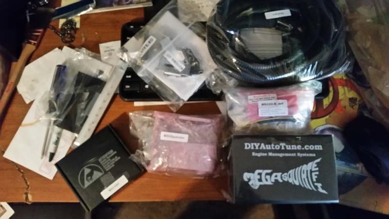
This is Megasquirt 3, with the ms3x expander card. Or at least it will be once I assemble all the components. I went ahead and got the MAPDaddy upgrade with the 4 bar map sensor since 21psi wont be enough for this build, its the main reason I went for a fresh MS build as opposed to using the MS3X I built for my Celica...since that one also has the lower MAP sensor that runs out at 21psi(which is fine for that car...at least for the moment) but will never work once you start using Holsets. This one will be good up to 42psi...more than I will ever use. I opted for the MS3X card because I plan on running full sequential fuel and spark this time around. It looks like I will have a fun 8 hours or so of assembly(judging by the last time I assembled one).

This is Megasquirt 3, with the ms3x expander card. Or at least it will be once I assemble all the components. I went ahead and got the MAPDaddy upgrade with the 4 bar map sensor since 21psi wont be enough for this build, its the main reason I went for a fresh MS build as opposed to using the MS3X I built for my Celica...since that one also has the lower MAP sensor that runs out at 21psi(which is fine for that car...at least for the moment) but will never work once you start using Holsets. This one will be good up to 42psi...more than I will ever use. I opted for the MS3X card because I plan on running full sequential fuel and spark this time around. It looks like I will have a fun 8 hours or so of assembly(judging by the last time I assembled one).
11-14-15, 08:30 PM
#40
Full Member
Thread Starter
Join Date: Aug 2015
Location: Columbia TN
Posts: 86
Likes: 0
Received 0 Likes
on
0 Posts

Finally got a day off to start assembling my MS3. This is the v3.0 blank board...same board used for either MS2 or MS3

And here we have the first circuit mostly completed..its the power supply circuit(and of course the connectors). MS assembly pictures arent a whole lot of fun to look at, but I thought I would document it anyway since its not often seen. I stopped there for the day since I ran out of daylight and didnt feel like pulling out a magnifying glass to read components by incandescent lighting.
05-11-19, 08:09 PM
#41
Full Member
Thread Starter
Join Date: Aug 2015
Location: Columbia TN
Posts: 86
Likes: 0
Received 0 Likes
on
0 Posts
Lord knows how long its been since I worked on this project car...I figured it was time to finish this thing up(or at least get it running).
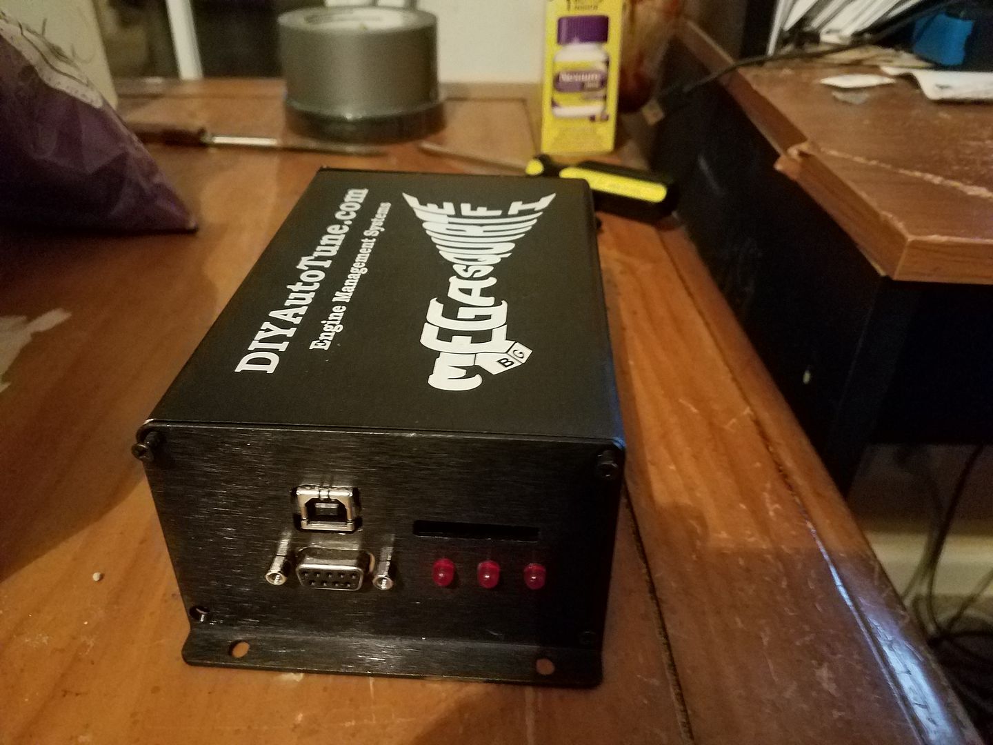
So I finally finished building this MS3 unit...all up and running on the stim...have a few things to do before I can try it on the real engine.
1. Need to do a little bit of work on the ITB transition to smooth out a few areas(would kill for a die grinder for this task).
2. Since a PWM stepper motor is on my list(but need to find the exact one I need to purchase) for the HE351VE, I need to rig up a bracket to lock the vanes in some reasonable range? maybe make the exhaust housing around 9cm for now for basic get-it-running tuning purposes?
3. Need to build the engine wiring harness...this should be a fun little project since I bought a 25 connector mil-spec firewall connector for the purpose:
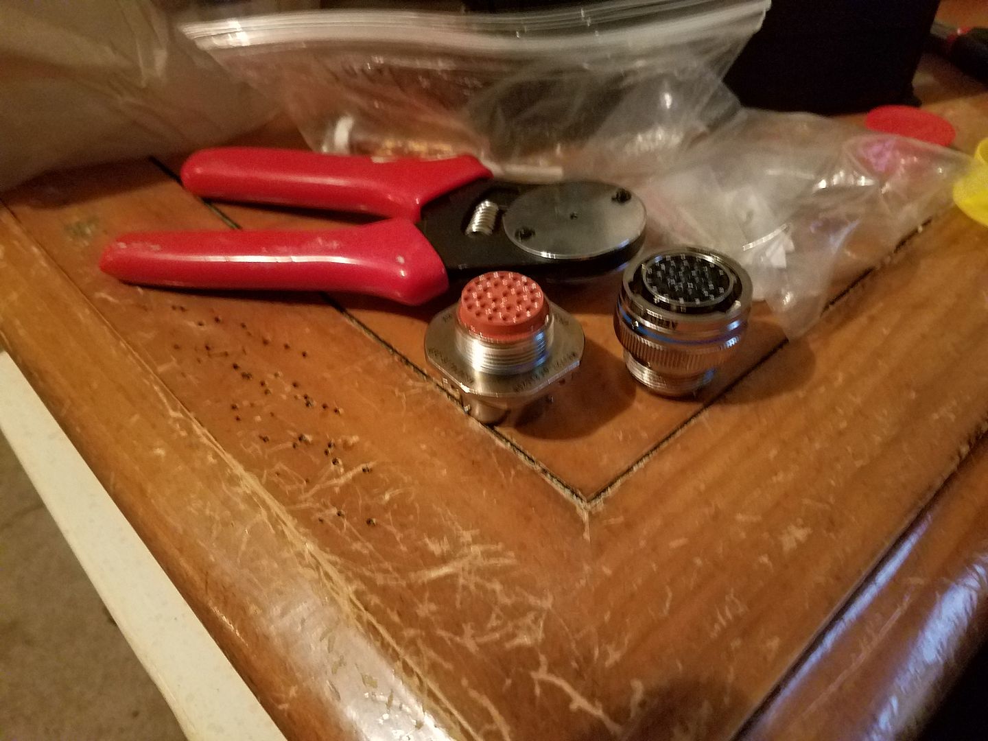
I guess I need to figure out something for the fuses and relays too...I really like DIYAutotune's fusebox....except for the fact that it doesn't allow an engine quick disconnect(and doesn't have a cover)
P.S. Evidently these days photobucket is so slow as to be almost worthless for hosting


Thread
Thread Starter
Forum
Replies
Last Post
Azevedo
Other Engine Conversions - non V-8
26
03-01-19 09:19 PM