Intake Manifold Casting
 03-07-15, 10:05 PM
#26
Moderator
iTrader: (3)
Join Date: Mar 2001
Location: https://www2.mazda.com/en/100th/
Posts: 30,778
Received 2,563 Likes
on
1,823 Posts
 03-07-15, 10:16 PM
#27
What was said about ambitious goals?
I want to buy a $400-600 ebay assemble yourself 3d printer and from there... build my own starting with a 2x2x2 foot build area... using a mig gun for metal printing... and then on to spening around $6000-8000 building a 10 by 15 by 10 metal printer( or multi material)... what's the point of un ambitious goals? I'm just concerned with getting it done before I'm too old.
as far as the home forge goes... the one i saw online that used a hairdryer to blow the air in one port, and an old fire extinguisher used for the crucible.. i plan to use 4 ports that come into base at an angle to get a swirl effect and provide lots of even heat so i that i can go beyond melting alum... how ever im not sure what to use as crucible if i am melting iron/steel. i feel like i should go find some books on metallurgy...
03-08-15, 08:52 AM
#29
spoon!
Thread Starter
lastphaseofthis, I'm 32 - all my stuff is self funded but I have a lot of stuff sitting around at my parent's place to cannabalize. The foundry was pretty much an example of that.
I attached a pic of the foundry at one point in its evolution... wife has better pics but she's busy and I just wanted to get something up before I start the day. It's a hot water heater shell filled with homemade castable refractory - recipe from the backyard metal casting site, basically a mix of cement, fireclay (well, oildry), perlite and sand. Inside opening is about 12" diameter and 18" tall, so plenty of room for a big crucible. Heat source is an oil burner from when my folks upgraded to a gas furnace. It's a great little thing - self contained igniter, blower and high pressure pump. Just feed it diesel and it goes. Since added an insulated lid for it on a hinge made out of a VW rabbit clutch pedal... because it was laying around. I think we have all of about $100 into it.
I have designs for a better, less... cobbled together version in mind if need be; this was essentially all to see if doing it at all was practical. So far so good.
edit: And the picture is rotated. Sorry, no time to sort that out right now.
03-29-15, 10:51 AM
#30
RotorHead
iTrader: (2)
Join Date: Mar 2005
Location: Beaverton, OR
Posts: 294
Likes: 0
Received 0 Likes
on
0 Posts
This is a great thread!!! Very interesting and encouraging for DIYer. At this rate with increasing interest we can finally make those hard to find parts or aftermarket ones. Found another trick.
http://gizmodo.com/turning-styrofoam...asy-1694298734
http://gizmodo.com/turning-styrofoam...asy-1694298734
03-29-15, 11:59 AM
#31
Moderator
iTrader: (3)
Join Date: Mar 2001
Location: https://www2.mazda.com/en/100th/
Posts: 30,778
Received 2,563 Likes
on
1,823 Posts
This is a great thread!!! Very interesting and encouraging for DIYer. At this rate with increasing interest we can finally make those hard to find parts or aftermarket ones. Found another trick.
Turning Styrofoam Into Aluminum is Surprisingly Easy
Turning Styrofoam Into Aluminum is Surprisingly Easy
03-29-15, 12:57 PM
#32
Red Pill Dealer
iTrader: (10)

This is a great thread!!! Very interesting and encouraging for DIYer. At this rate with increasing interest we can finally make those hard to find parts or aftermarket ones. Found another trick.
Turning Styrofoam Into Aluminum is Surprisingly Easy
Turning Styrofoam Into Aluminum is Surprisingly Easy
One more note on Pettersen's video for people interested in this. In the vid he puts a pre-made solid sand core in the sand impression made by the pattern. Where did that come from? It comes from a core box. One uses a different mold to make the sand core. A different sand, using a different binder, is packed into the core box and then baked to solidify the core. The core box has to have provisions for supporting the core in the cavity and so does the pattern. It shows this in the video.
Even with this it is still not all that complicated. Patterns can be like the ones in the video or split and placed on each side of a flat piece of wood big enough to cover the surface of the cope and the drag. This allows preparing of both halves before closing the mold and insures that the cavity is in the proper position between both halves.
03-29-15, 09:21 PM
#33
spoon!
Thread Starter
Actually worked on this today; had some issues with the print. No big deal, just that wide flat items (ala flanges) tend to warp. Trying something different; we'll see.
One nice thing that can be done too is making core boxes with the printer too; investment casting from the plastic directly is nice for one-offs but sand casting is probably going to be necessary for any sort of production. In theory it should all work just as well with cast iron, if I could melt cast iron, which I can't yet, heh. Maybe someday.
One nice thing that can be done too is making core boxes with the printer too; investment casting from the plastic directly is nice for one-offs but sand casting is probably going to be necessary for any sort of production. In theory it should all work just as well with cast iron, if I could melt cast iron, which I can't yet, heh. Maybe someday.

 03-31-15, 02:03 AM
#37
You will get warping and cracks due to stress in the materials when they are cooling down, but there are some methods to fix this.
You could try to bake them in an oven while you put pressure on them, wich should get them close where they need to be.
A better alternative, would be to build a box around the 3d printer and heat it up, so the newly laid plastic cools slower, wich should help. Just find out maximum enviroment temperature for your 3D printer, and heat it a little under that, just make shure the heat from the printer itself doesn't push it above the limit.
In my experience pls is a better choice than abs(not shure what you are using?), cause it requires less heat, so there is less stress created in the material.
Printing several smaller parts and gluing them together could also work.
03-31-15, 05:46 AM
#39
spoon!
Thread Starter
It's a shared machine that's not at my apartment so I don't get as much of a chance to finetune the settings as I might like. Looking to fix that. Right now it's PLA onto unheated Kapton tape. The intent was already to do it in two halves (printer won't fit the whole thing) but the flange where it bolts to the engine is a certain size and really has to be a certain thickness.
Next try is going to be turning it the part 90 degrees - instead of the big flange sitting flat on the bed, it'll be sitting edge-on. That should make it easier to do as a thinner shell too instead of trying to make a 6mmish thick PLA plate. Been a little while since I messed with this stuff.
Next try is going to be turning it the part 90 degrees - instead of the big flange sitting flat on the bed, it'll be sitting edge-on. That should make it easier to do as a thinner shell too instead of trying to make a 6mmish thick PLA plate. Been a little while since I messed with this stuff.
03-31-15, 06:54 AM
#40
I'm aware it has to be a certain thickness, but if you design it hollow, and use honeycomb support structure, it will be much faster to print and less likely to warp. You can still have it 10mm thick, but only 2mm solid shell filled with support structure.
03-31-15, 05:08 PM
#41
spoon!
Thread Starter
I think we're on the same page... it was hollow, but when it was more than a few layers in, it pulled off the bed. I could probably fine tune settings to get it to work at the same orientation, but like I said, I think printing from a different angle will fix it in one shot.
04-24-15, 05:14 PM
#42
spoon!
Thread Starter
Okay, new printer of my own... much more rigid, heated PEI build surface, etc etc etc. Half scale test more or less worked! It's literally my second print on this machine and I need to fine tune extrusion so it's thin in spots, but it's there. Pictures tomorrow when I can actually get decent lighting on it.
04-29-15, 07:27 PM
#43
spoon!
Thread Starter
Okay, now I have to remember how to get pictures into the body of the post... ugh. This will probably get edited a few times as I screw with it. 
Well, anyway, a couple days late, but here's a half scale printed version to check it for ability to be printed. Next step is to do a bit of known dimensions and cast it, then measure it afterwards to be able to quantify shrinkage and so forth. Yes, I know that all of this is theoretically known, but there's no substitute for testing. After that, full scale!
Edit: Hey hey, got it!
Last edited by Kenku; 04-29-15 at 07:29 PM.
04-29-15, 07:33 PM
#44
spoon!
Thread Starter
Oh yeah, while I'm thinking of it. The printer I built can actually do pretty much anything including nylon. In theory. There's still issues with FDM stuff being kinda porous but I could maybe do a nylon intake manifold. Except the lower intake on the RX-8 is still aluminum and I can't help but think there's a reason for that.
Second off, this manifold is intended for Arctic Cat snowmobile throttle bodies, but I was thinking of doing an IPRA style manifold for GSXR throttle bodies too. And for that matter, curved manifolds that will actually fit into normal cars rather than just the specific Lotus 7 clone I'm building.
Second off, this manifold is intended for Arctic Cat snowmobile throttle bodies, but I was thinking of doing an IPRA style manifold for GSXR throttle bodies too. And for that matter, curved manifolds that will actually fit into normal cars rather than just the specific Lotus 7 clone I'm building.
04-29-15, 08:58 PM
#45
Moderator
iTrader: (3)
Join Date: Mar 2001
Location: https://www2.mazda.com/en/100th/
Posts: 30,778
Received 2,563 Likes
on
1,823 Posts
i've discovered with the 3d print, there is actually a big tolerance, so you wanna do some careful measuring to make sure it came out like you intended
04-29-15, 09:32 PM
#46
spoon!
Thread Starter
Yeah, working on that too. Last calibration piece I measured out what about a a percent under CAD size, but at least it was nice and square. Fine tuning a bunch of little things - what would be the fun if there weren't still things to learn how to do?
05-03-15, 09:56 PM
#47
spoon!
Thread Starter
Okay, cast a calibration cube today. Theoretical size was 40mm cubed - actual printed size was about 39.6x39.6x41mm or so... I have it written down. Size after casting... will be TBD. I want to use the same equipment to measure it that I did beforehand which means the sutff at work.

Here's the foundry. Yes, it's very very hacked together. Shell is a hot water heater tank, and it's lined with homemade castable refractory. Lid has the same plus some rebar. Heat source is the burner on the lower right side; it's a fuel oil burner we had leftover from converting to gas heat. Hinge is a VW Rabbit clutch pedal with some stuff welded to it - hey, it was handy. Inside size is something like 12" ID by 18" tall. I haven't taken a precise measurement, but burning diesel, getting from room temperature to pouring temperature for a couple pounds of scrap aluminum takes all of about half an hour.
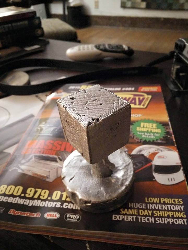
This is the result. A few casting defects, probably because I didn't put any vents in or possibly because the aluminum temperature may have been a bit high. Or maybe I didn't let it burn out long enough. One way or another though, they're just surface defects and it should be close enough to let me establish a scaling factor.
Here's the foundry. Yes, it's very very hacked together. Shell is a hot water heater tank, and it's lined with homemade castable refractory. Lid has the same plus some rebar. Heat source is the burner on the lower right side; it's a fuel oil burner we had leftover from converting to gas heat. Hinge is a VW Rabbit clutch pedal with some stuff welded to it - hey, it was handy. Inside size is something like 12" ID by 18" tall. I haven't taken a precise measurement, but burning diesel, getting from room temperature to pouring temperature for a couple pounds of scrap aluminum takes all of about half an hour.
This is the result. A few casting defects, probably because I didn't put any vents in or possibly because the aluminum temperature may have been a bit high. Or maybe I didn't let it burn out long enough. One way or another though, they're just surface defects and it should be close enough to let me establish a scaling factor.
05-03-15, 11:09 PM
#48
Red Pill Dealer
iTrader: (10)
Venting and thermal conductivity is where your problems are. Plus, fill. Fill at the bottom and use a stouter runner. Yeah, more waste but it's sand casting...
05-04-15, 05:58 AM
#49
spoon!
Thread Starter
Yeah, I was taking far from every precaution I could think of; the sprue was literally a heated up candle that I jammed into one side of the cube before investing it in plaster. I was thinking for the intake manifold attempt, something like a 1 1/2-2" sprue between the throttle bodies, maybe half a dozen 1/2-3/4" gates going to various parts of the manifold and a bunch of 1/4" or so risers coming up.
At this rate maybe I should do something smaller with fine details before I try to do the intake manifold. Hm.
At this rate maybe I should do something smaller with fine details before I try to do the intake manifold. Hm.
05-04-15, 09:34 AM
#50
Moderator
iTrader: (3)
Join Date: Mar 2001
Location: https://www2.mazda.com/en/100th/
Posts: 30,778
Received 2,563 Likes
on
1,823 Posts
Yeah, I was taking far from every precaution I could think of; the sprue was literally a heated up candle that I jammed into one side of the cube before investing it in plaster. I was thinking for the intake manifold attempt, something like a 1 1/2-2" sprue between the throttle bodies, maybe half a dozen 1/2-3/4" gates going to various parts of the manifold and a bunch of 1/4" or so risers coming up.
At this rate maybe I should do something smaller with fine details before I try to do the intake manifold. Hm.
At this rate maybe I should do something smaller with fine details before I try to do the intake manifold. Hm.

