FB S5 ITB Project
 04-15-14, 08:41 PM
#1
ERTW
Thread Starter
iTrader: (2)

Join Date: Nov 2004
Location: Waterloo, Ontario
Posts: 880
Likes: 0
Received 0 Likes
on
0 Posts
FB S5 ITB Project
Sorry... there are some large pictures in this thread... turns out photobucket won't re-size them automatically.
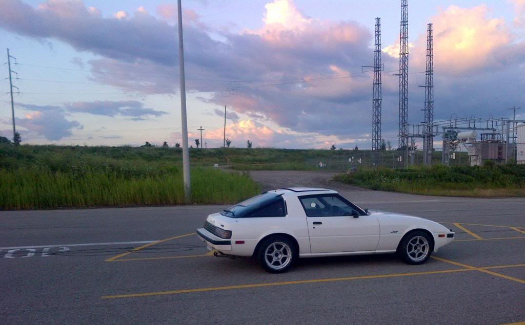
Anyhoo, I've got a nicely prepped '84 GSL-SE with full suspension, street-ported S5 engine running on Electromotive TEC 3 standalone, full exhaust, electric fan, etc. etc. blah blah blah.
Last year I made some tuning changes by switching from staged injection running 640/400cc injectors to running ID1000s as primaries only. I also added an IAC as I had previously been running without and the engine would always stall out and never idled very clean using timing advance to control idle speed. I also installed a new AEM UEGO wideband.
I completely retuned the engine but never was able to get the engine to idle stable and strong. Since I had the aux port sleeves removed, I think port velocity through the primaries wasn't substantial enough to carry the fuel through the port and into the housing without pooling in the port. That, coupled with the wide variance in engine load at idle caused by the rad fan switching on/off resulted in an engine that would still die-out under certain idling conditions.
So to summarize, I was never really able to nail the tune and idle, and I ended up attributing it to the overly complex (but suitable for some applications) S5 intake manifold; with VDI, dual stage throttle body, and aux ports. Also, according to the interwebz, it doesn't flow very well. BUT, there are no longer any off-the-shelf ITB setups or alternative intake systems available on the market anymore.
But then one day I was perusing this forum and came across the following thread:
https://www.rx7club.com/forum/1st-ge...ussion-945202/
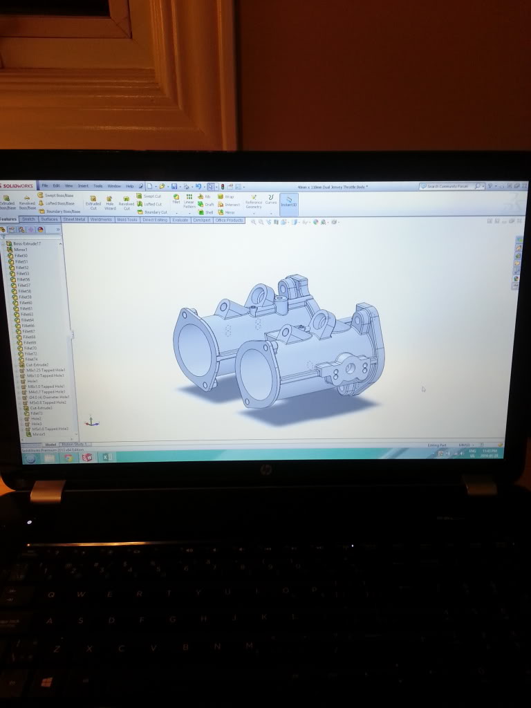
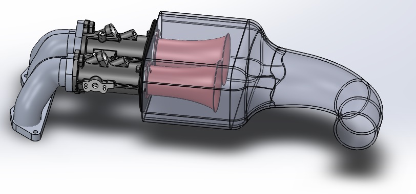
So I fired up Solidworks and started to model the ITB and manifold. My plan here was to check fit and position using the complete 13B engine model I have but never got to that point yet. I might use it for a future plenum design but who knows:
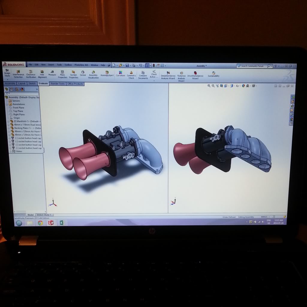
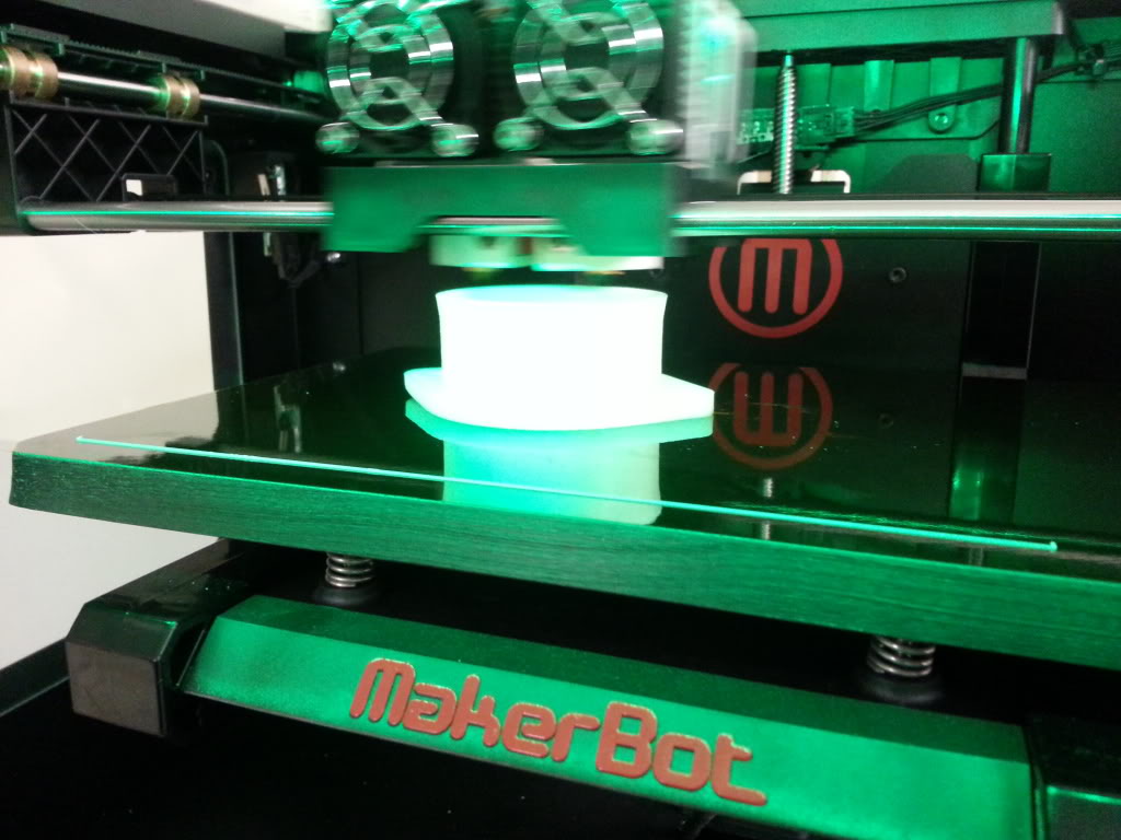
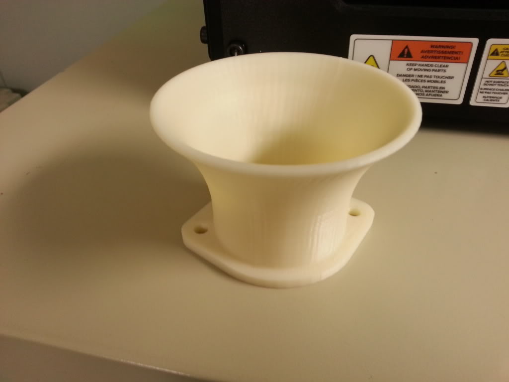
Using the model I designed some 60mm length air horns and then 3D printed them on a Makerbot Replicator 2X:
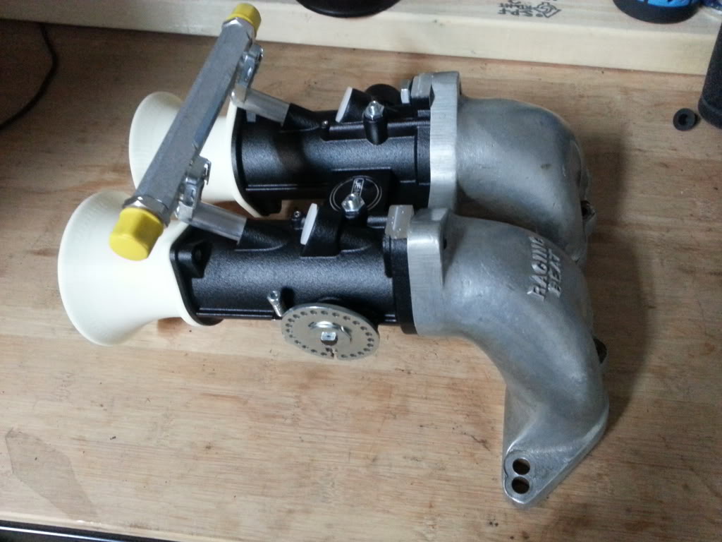
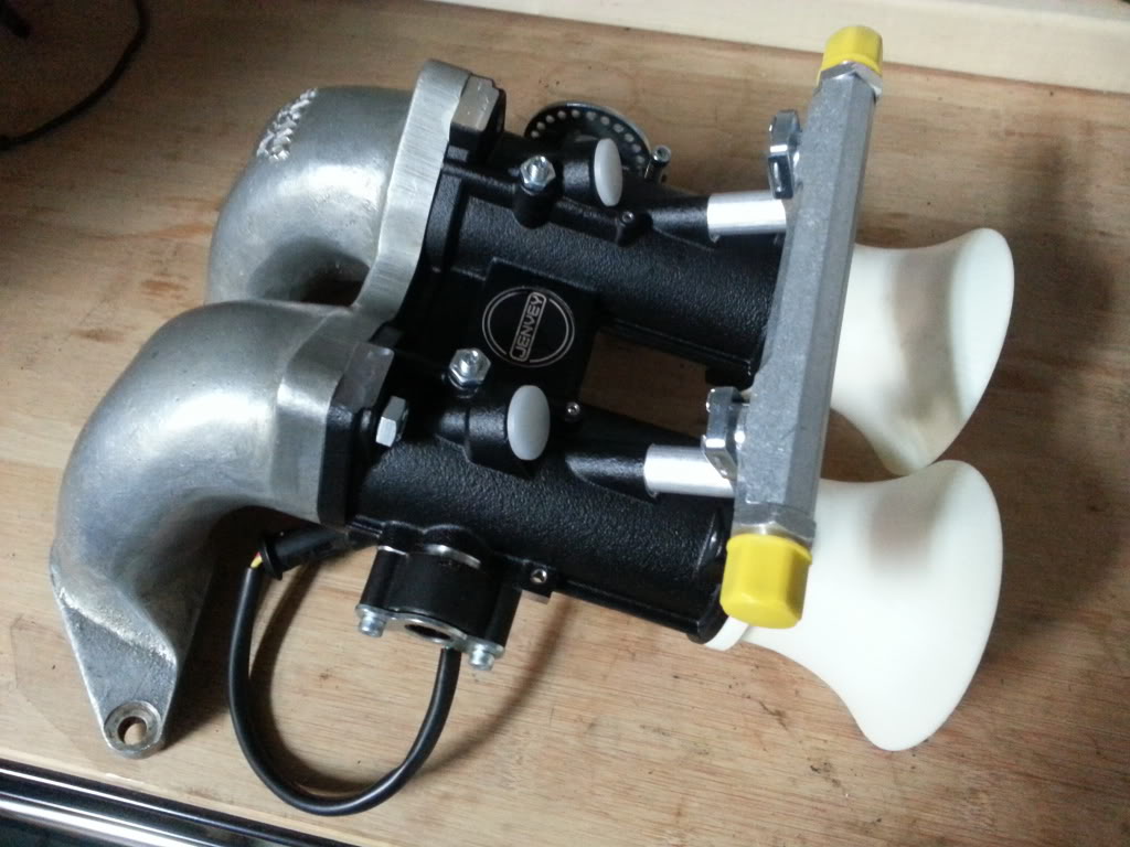
Then a box from the U.K. arrived and I assembled everything together:
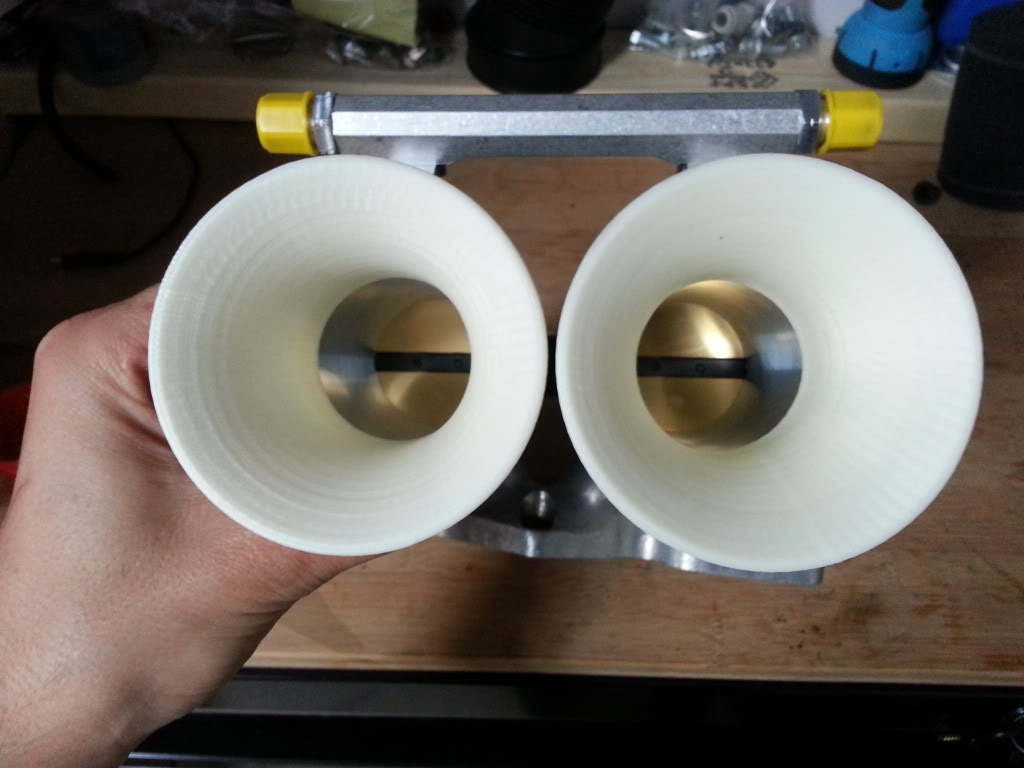
Not shown is the foam filter sock I ordered off eBay.
So this is my project so far. I plan on bringing my RX7 home from storage tomorrow if the weather holds up and then beginning the installation.
To do:
- Design and fab some sort of throttle cable mount.
- Find a mounting spot for the IAC motor and housing (Rising RPM for S5 turbo) and potentially 3D print some more parts. I'm thinking of just running two ports into the primary ports in the LIM.
- Tap and install two 3/8"NPT x 6mm push lock fittings into each runner of the intake manifold, run those into a tee, then run that into a vacuum manifold, then run a line from the manifold to the MAP, FPR, and oil injectors. The goal here is to smooth out the pulsations in the manifold so the varying vacuum and MAP signal doesn't cause the EMS to flip out... which may not even be required due to a setting in WinTEC.
- Mount intake air temperature sensor.
- Remove ID1000s and swap in 400cc primaries and ~600cc secondaries.
- Re-plumb engine fuel lines using AN fittings.
- Re-tune engine.
More pictures to follow...
Anyhoo, I've got a nicely prepped '84 GSL-SE with full suspension, street-ported S5 engine running on Electromotive TEC 3 standalone, full exhaust, electric fan, etc. etc. blah blah blah.
Last year I made some tuning changes by switching from staged injection running 640/400cc injectors to running ID1000s as primaries only. I also added an IAC as I had previously been running without and the engine would always stall out and never idled very clean using timing advance to control idle speed. I also installed a new AEM UEGO wideband.
I completely retuned the engine but never was able to get the engine to idle stable and strong. Since I had the aux port sleeves removed, I think port velocity through the primaries wasn't substantial enough to carry the fuel through the port and into the housing without pooling in the port. That, coupled with the wide variance in engine load at idle caused by the rad fan switching on/off resulted in an engine that would still die-out under certain idling conditions.
So to summarize, I was never really able to nail the tune and idle, and I ended up attributing it to the overly complex (but suitable for some applications) S5 intake manifold; with VDI, dual stage throttle body, and aux ports. Also, according to the interwebz, it doesn't flow very well. BUT, there are no longer any off-the-shelf ITB setups or alternative intake systems available on the market anymore.
But then one day I was perusing this forum and came across the following thread:
https://www.rx7club.com/forum/1st-ge...ussion-945202/
So I fired up Solidworks and started to model the ITB and manifold. My plan here was to check fit and position using the complete 13B engine model I have but never got to that point yet. I might use it for a future plenum design but who knows:
Using the model I designed some 60mm length air horns and then 3D printed them on a Makerbot Replicator 2X:
Then a box from the U.K. arrived and I assembled everything together:
Not shown is the foam filter sock I ordered off eBay.
So this is my project so far. I plan on bringing my RX7 home from storage tomorrow if the weather holds up and then beginning the installation.
To do:
- Design and fab some sort of throttle cable mount.
- Find a mounting spot for the IAC motor and housing (Rising RPM for S5 turbo) and potentially 3D print some more parts. I'm thinking of just running two ports into the primary ports in the LIM.
- Tap and install two 3/8"NPT x 6mm push lock fittings into each runner of the intake manifold, run those into a tee, then run that into a vacuum manifold, then run a line from the manifold to the MAP, FPR, and oil injectors. The goal here is to smooth out the pulsations in the manifold so the varying vacuum and MAP signal doesn't cause the EMS to flip out... which may not even be required due to a setting in WinTEC.
- Mount intake air temperature sensor.
- Remove ID1000s and swap in 400cc primaries and ~600cc secondaries.
- Re-plumb engine fuel lines using AN fittings.
- Re-tune engine.
More pictures to follow...
 04-21-14, 11:59 AM
#3
Jolly Green Giant
iTrader: (1)
Join Date: Feb 2008
Location: San Antonio, TX
Posts: 509
Likes: 0
Received 0 Likes
on
0 Posts
If you don't mind me picking your brain, here are my latest ideas/thoughts on it and I would love to hear what you think.
1. Have you though about making a thermal spacer for the intake manifold (lim/keg or lim/uim)? That makerbot (insanely jealous) would make life easier and it would help control the way that intake (especially the RB upper) soaks up heat. This was more prudent for me with a carb since it would heat soak the carb very quickly but would still be a neat piece.
2. What are your plans for ECU?
3. Any thoughts on possible building an airbox? This one is a longshot but it's something I am going to start on this week with atleast measuring space. My reasoning is using the oval stack filter like with the DCOE or DHLA, when sitting still or low speeds it's just sucking air directly off the top of the engine....also I have come to realize that K&N filters are good for keeping birds out and nothing much better. The idea is to build an aluminum box (thermal reflective tape around) with a top mounted rectangular panel paper filter (honda) so you can use a good filter and it's atleast pulling air from a somewhat cooler place but also with a first gen it's easier to "space" the hood so air flows up and out the top of the engine.
4. This might be answered with your ECU choice but, why the choice of staged injectors vs. 2 sizable injectors n/a (a'la GSL-SE).
5. For the 5+6 ports, I'm not super versed on S5 stuff but have you thought about doing an RPM trigger and using a small horn air-pump to power the actuators? I've seen it done a few times and is hopefully the plan for my S3 setup.
04-23-14, 07:45 PM
#4
ERTW
Thread Starter
iTrader: (2)
Join Date: Nov 2004
Location: Waterloo, Ontario
Posts: 880
Likes: 0
Received 0 Likes
on
0 Posts
If you don't mind me picking your brain, here are my latest ideas/thoughts on it and I would love to hear what you think.
1. Have you though about making a thermal spacer for the intake manifold (lim/keg or lim/uim)? That makerbot (insanely jealous) would make life easier and it would help control the way that intake (especially the RB upper) soaks up heat. This was more prudent for me with a carb since it would heat soak the carb very quickly but would still be a neat piece.
1. Have you though about making a thermal spacer for the intake manifold (lim/keg or lim/uim)? That makerbot (insanely jealous) would make life easier and it would help control the way that intake (especially the RB upper) soaks up heat. This was more prudent for me with a carb since it would heat soak the carb very quickly but would still be a neat piece.
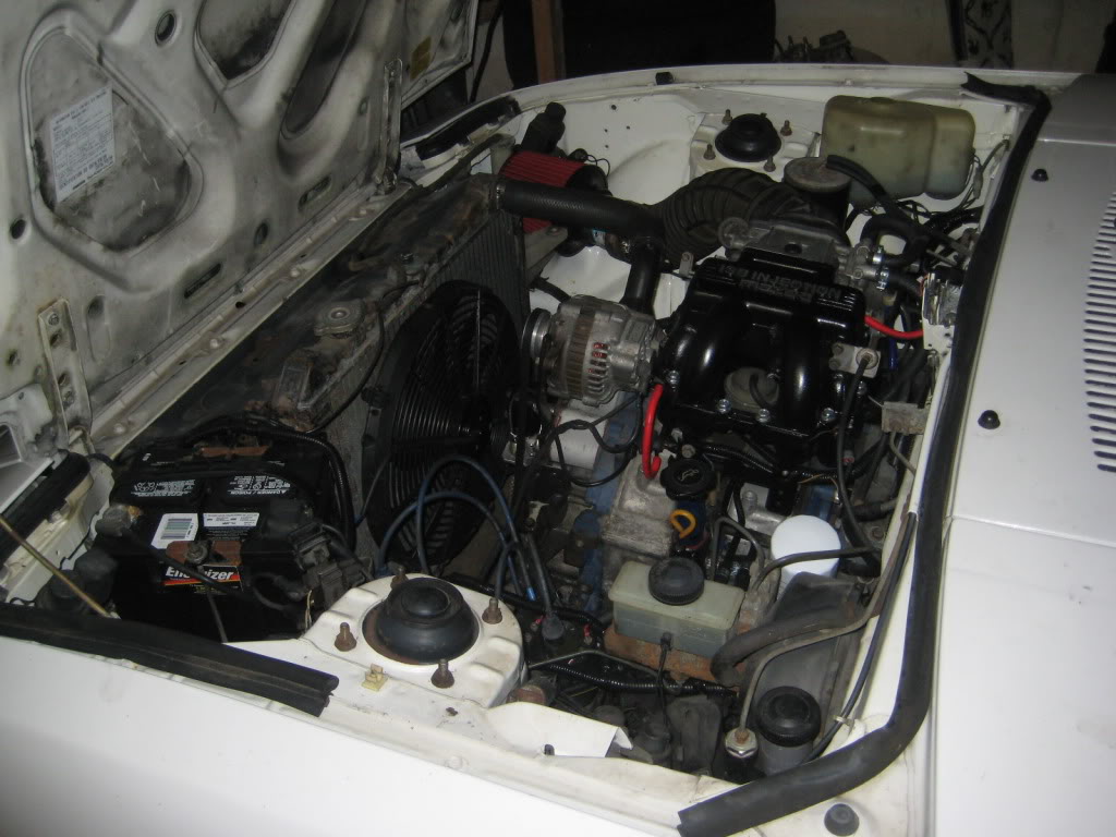
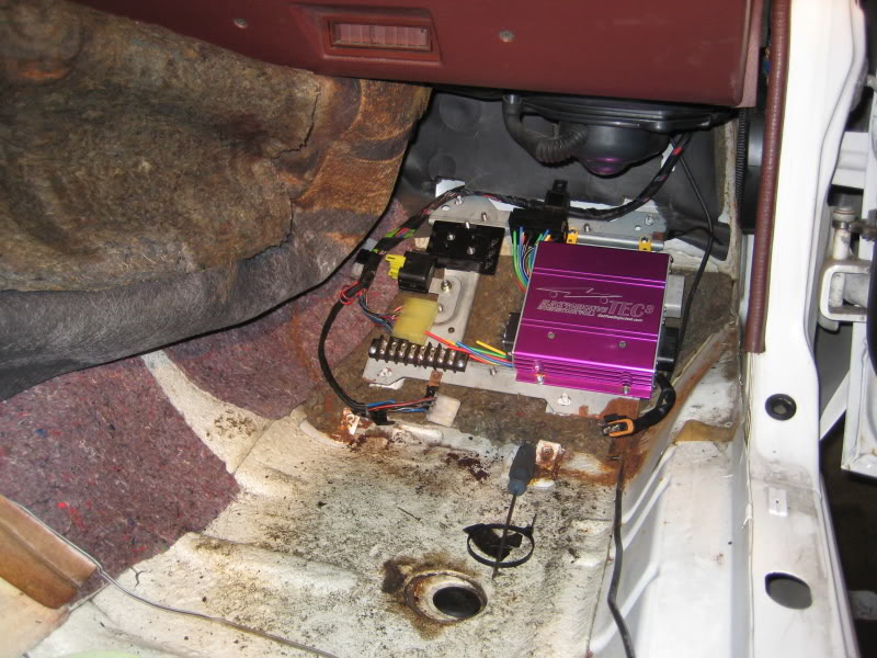
The car already has an Electromotive TEC3 standalone installed (picture taken during installation):
3. Any thoughts on possible building an airbox? This one is a longshot but it's something I am going to start on this week with atleast measuring space. My reasoning is using the oval stack filter like with the DCOE or DHLA, when sitting still or low speeds it's just sucking air directly off the top of the engine....also I have come to realize that K&N filters are good for keeping birds out and nothing much better. The idea is to build an aluminum box (thermal reflective tape around) with a top mounted rectangular panel paper filter (honda) so you can use a good filter and it's atleast pulling air from a somewhat cooler place but also with a first gen it's easier to "space" the hood so air flows up and out the top of the engine.
The normal solution to these problems is to run smaller injectors. But with our engines, the fueling requirements are such that this is impossible. I reached something like 90% duty cycle at high RPM WOT with these injectors, which is pushing the limits.
So the solution is to run two smaller injectors in place of one large. I have a set of DEKA 640cc/min injectors from an SRT4 that I'm going to try. This should get me the controllability of a smaller injectors since I'm only running a single 640cc injector at idle and low load, while being able to kick in another injector to provide the fueling requirements of the rotary at high loads where injector precision isn't an issue.

 05-01-14, 06:29 PM
#6
Exhaust Manifold Leak
for the airbox I would print a mold and make it with carbon fiber or glas fiber. some of these 3D printer can print material that disolves with acid..

Trending Topics
 03-18-18, 11:03 PM
#12
Junior Member

Whatever happened to the car shown in this thread? Did it sell? I thought the engine modifications were top flight. I am always interested in what a well cared for RX7 sold for, as I am in the market for such a car. Respectfully, John J. Garvey
