Megasquirt Forum Area is for discussing Megasquirt EMS

Megasquirt Ls2 coil noise???

Thread Tools
 
Search this Thread
 
Old 03-13-16, 02:47 PM
  #26  
Senior Member

 
elturbonitroso's Avatar
 
Join Date: Nov 2006
Location: connecticut
Posts: 461
Likes: 0
Received 13 Likes on 12 Posts
did you put the 10k resisitors on both signals.
Old 03-13-16, 04:08 PM
  #27  
Ratchet_Brap
Thread Starter
 
Scrappy_Brap's Avatar
 
Join Date: Aug 2013
Location: Kentucky
Posts: 153
Likes: 0
Received 0 Likes on 0 Posts
No when I talked to Matt at DIY and sent him the composite log he just told me to put a 10k resistor between the CMP+ and CMP- wires, that fixed the 17 code,
Old 03-13-16, 06:20 PM
  #28  
Senior Member

 
elturbonitroso's Avatar
 
Join Date: Nov 2006
Location: connecticut
Posts: 461
Likes: 0
Received 13 Likes on 12 Posts
put a 10k on both signals.
Old 03-14-16, 07:21 AM
  #29  
Ratchet_Brap
Thread Starter
 
Scrappy_Brap's Avatar
 
Join Date: Aug 2013
Location: Kentucky
Posts: 153
Likes: 0
Received 0 Likes on 0 Posts
Is there any specific way to wire them in?
Old 03-15-16, 03:41 PM
  #30  
Senior Member

 
elturbonitroso's Avatar
 
Join Date: Nov 2006
Location: connecticut
Posts: 461
Likes: 0
Received 13 Likes on 12 Posts
no just put them between the vr signals.
Old 03-22-16, 09:10 AM
  #31  
Ratchet_Brap
Thread Starter
 
Scrappy_Brap's Avatar
 
Join Date: Aug 2013
Location: Kentucky
Posts: 153
Likes: 0
Received 0 Likes on 0 Posts
Do you have a diagram of photo you could provide? I'm not quite sure I understand (im new to this lol
Old 03-23-16, 03:34 PM
  #32  
Senior Member

 
elturbonitroso's Avatar
 
Join Date: Nov 2006
Location: connecticut
Posts: 461
Likes: 0
Received 13 Likes on 12 Posts
the resistor goes between vr+ and vr- on both signals.
Old 03-24-16, 10:03 AM
  #33  
Ratchet_Brap
Thread Starter
 
Scrappy_Brap's Avatar
 
Join Date: Aug 2013
Location: Kentucky
Posts: 153
Likes: 0
Received 0 Likes on 0 Posts
I don't understand what you mean about the Vr+ and Vr-, please specify which wires I am running a resistor in between


Old 03-24-16, 05:42 PM
  #34  
Senior Member

 
elturbonitroso's Avatar
 
Join Date: Nov 2006
Location: connecticut
Posts: 461
Likes: 0
Received 13 Likes on 12 Posts
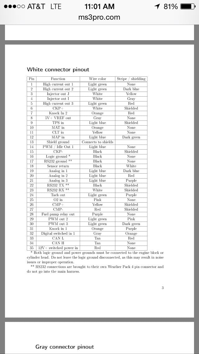
the resistor goes between ckp + and ckp - and cmp+ and cmp -
Old 03-24-16, 07:46 PM
  #35  
Ratchet_Brap
Thread Starter
 
Scrappy_Brap's Avatar
 
Join Date: Aug 2013
Location: Kentucky
Posts: 153
Likes: 0
Received 0 Likes on 0 Posts
Okay I see now, i currently have a 10k resistor between the CMP wires, I'll put one in between the CKP wires and I'll keep you guys posted! Thanks!
Old 03-25-16, 05:58 AM
  #36  
Senior Member

 
elturbonitroso's Avatar
 
Join Date: Nov 2006
Location: connecticut
Posts: 461
Likes: 0
Received 13 Likes on 12 Posts
Originally Posted by Scrappy_Brap
Okay I see now, i currently have a 10k resistor between the CMP wires, I'll put one in between the CKP wires and I'll keep you guys posted! Thanks!
if the 10k don't do the trick then put a 1k
Old 03-25-16, 08:28 AM
  #37  
Ratchet_Brap
Thread Starter
 
Scrappy_Brap's Avatar
 
Join Date: Aug 2013
Location: Kentucky
Posts: 153
Likes: 0
Received 0 Likes on 0 Posts
The current 10k fixed the 17 code, hopefully a 2nd 10k resistor will fix the 11... If not I need to go 1k?
Old 03-25-16, 10:11 AM
  #38  
Engine, Not Motor

iTrader: (1)
 
Aaron Cake's Avatar
 
Join Date: Feb 2001
Location: London, Ontario, Canada
Posts: 29,789
Likes: 0
Received 108 Likes on 91 Posts
You may have to experiment with values as you are trying to find the value which puts just enough load on the VR sensor to take up the small spikes but does not load the sensor enough that at low RPMs the signal is too weak.
Old 03-25-16, 10:55 AM
  #39  
Ratchet_Brap
Thread Starter
 
Scrappy_Brap's Avatar
 
Join Date: Aug 2013
Location: Kentucky
Posts: 153
Likes: 0
Received 0 Likes on 0 Posts
I guess I see where my saturday will be spent haha, will update as I make "progress"
Old 04-20-16, 06:59 AM
  #40  
Rotary Freak

iTrader: (7)
 
Shainiac's Avatar
 
Join Date: Jun 2006
Location: Lyme, CT
Posts: 1,575
Received 42 Likes on 31 Posts
Sorry to thread jack, but I’m trying to eliminate coil noise and 11/17 sync loss on a MS2V3.0 with a Zeal card for the second VR. Stock coils and CAS.
I put a 10K resistor on the VR2 OUT back to the main board, but are you guys recommending putting bridging a resistor between VR+/VR- ? or one resistor from VR+ to the board and another for VR- to the board?

For the MS2, VR1 comes in on pins 2 and 24 and VR2 uses the IAC spares. It’s easy enough to intercept VR2 +/- at the Zeal card, but I’m not sure its possible to add resistors to VR1 since I do not have access to the wiring harness.

Thanks
Old 04-21-16, 10:39 AM
  #41  
MegaSquirt Mod

 
muythaibxr's Avatar
 
Join Date: Sep 2004
Location: Maryland
Posts: 4,721
Likes: 0
Received 1 Like on 1 Post
Putting in resistors won't necessarily help. Which of the 2 VR inputs on the Zeal board did you use?
Old 04-21-16, 11:17 AM
  #42  
Rotary Freak

iTrader: (7)
 
Shainiac's Avatar
 
Join Date: Jun 2006
Location: Lyme, CT
Posts: 1,575
Received 42 Likes on 31 Posts
Ken,
I believe it's using VR1 for G+/G-
I'm using the mainboard VR circuit for N+/N-
Pots are adjusted correctly and was getting sync loss with multiple different CAS's and no resistor.
I just added a 10k inline with the VR2 Zeal output and the input to the CPU (JS10).

Any suggestions before I ship it back to the owner?
Old 04-25-16, 08:54 AM
  #43  
Rotary Freak

iTrader: (7)
 
Shainiac's Avatar
 
Join Date: Jun 2006
Location: Lyme, CT
Posts: 1,575
Received 42 Likes on 31 Posts
Does anyone have any advice on the above? I need to ship this ECU on 2 days and want to eliminate any sync loss.
Old 04-25-16, 01:47 PM
  #44  
Senior Member

 
elturbonitroso's Avatar
 
Join Date: Nov 2006
Location: connecticut
Posts: 461
Likes: 0
Received 13 Likes on 12 Posts
you dont need the 10k on the output of the seal board try a 1k shunt resistor on the 2nd trigger.
Old 04-25-16, 07:33 PM
  #45  
Rotary Freak

iTrader: (7)
 
Shainiac's Avatar
 
Join Date: Jun 2006
Location: Lyme, CT
Posts: 1,575
Received 42 Likes on 31 Posts
Thanks, so a 1k resistor across VR+/VR- and remove the 10k on VR2 out? I've also read about a resistor on the VR+. Good idea?
Old 04-26-16, 09:01 AM
  #46  
Senior Member

 
elturbonitroso's Avatar
 
Join Date: Nov 2006
Location: connecticut
Posts: 461
Likes: 0
Received 13 Likes on 12 Posts
Originally Posted by Shainiac
Thanks, so a 1k resistor across VR+/VR- and remove the 10k on VR2 out? I've also read about a resistor on the VR+. Good idea?
Yes
Old 04-28-16, 09:55 AM
  #47  
MegaSquirt Mod

 
muythaibxr's Avatar
 
Join Date: Sep 2004
Location: Maryland
Posts: 4,721
Likes: 0
Received 1 Like on 1 Post
For 2nd trig, you should be using VR2. It's set up correctly for the 2nd trigger.
Old 04-28-16, 12:04 PM
  #48  
Rotary Freak

iTrader: (7)
 
Shainiac's Avatar
 
Join Date: Jun 2006
Location: Lyme, CT
Posts: 1,575
Received 42 Likes on 31 Posts
VR1 and VR2 on the Zeal are physically different? I'm not 100% positive which I used. I already added the 1k shunt resistor and mailed the ECU back to the owner (my old ECU).
Old 05-02-16, 09:26 PM
  #49  
MegaSquirt Mod

 
muythaibxr's Avatar
 
Join Date: Sep 2004
Location: Maryland
Posts: 4,721
Likes: 0
Received 1 Like on 1 Post
Yes they are different. VR1 is set up for the primary (Ne) trigger. VR2 is set up for the secondary (G) trigger. This should also be documented with the board's docs.

The secondary is a lot more susceptible to noise and therefore needs more filtering at the electronic level.
Related Topics
Thread
Thread Starter
Forum
Replies
Last Post
00SPEC
3rd Generation Specific (1993-2002)
9
02-04-16 10:06 PM
Villanz415
New Member RX-7 Technical
4
02-03-16 08:22 PM
Charlie Genovese
New Member RX-7 Technical
1
02-03-16 12:32 PM


Quick Reply: Megasquirt Ls2 coil noise???


All times are GMT -5. The time now is 07:08 PM.