When you click on links to various merchants on this site and make a purchase, this can result in this site earning a commission. Affiliate programs and affiliations include, but are not limited to, the eBay Partner Network.
Sorry for the delay in getting this thread updated, work has been busy, but I finally have some progress!
As for fitting to a Re-Amemiya front end, I only have access to my own car which is running a '99 lip. If enough people are interested I could develop something, but I would need some measurements from this bumper.
I will be working on the lip side inlet fitted duct once the design is finalized for the rotor side duct.
Personally I think the extra drag induced by a smaller cross sectional area at the rotor is worth directing the flow into the center of the rotor and towards the vanes. I am considering adding a lip or soft seal to get as close to the rotor surface as possible to ensure a maximum amount of air flows into the rotor vanes. If the drag is too much for people they can always tape off the inlet ducts!
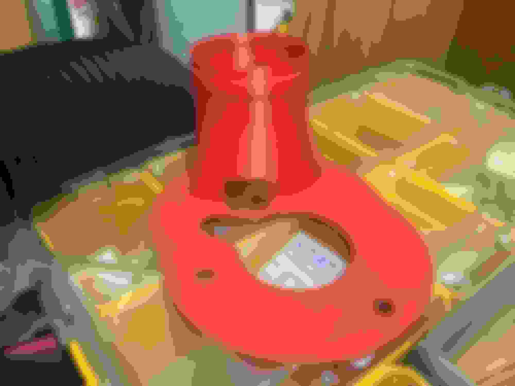
Finally found some time to get the geometry to something I felt was good enough to print out in plastic:
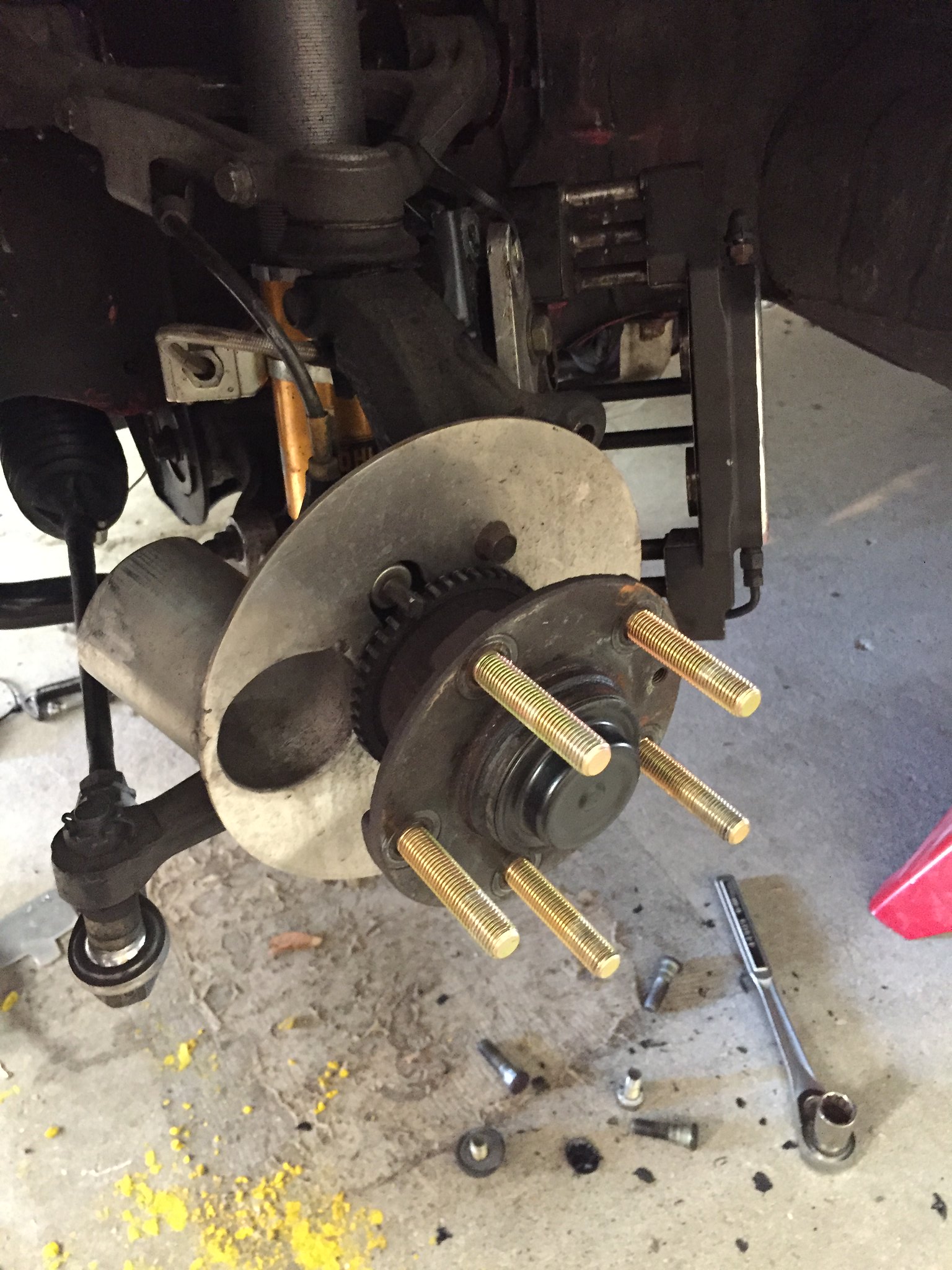
Fitted up to driver side spindle:
Closeup of gap around third bolt hole. I will be using a high temp capable RTV sealant to close this out completely. Also planning to run a few simulations to see if this bolt is needed to keep the duct in place under high loading (bump, high cornering, at elevated temp wet conditions).
Matches my centric slotted rotor ID perfectly... (view from inside)
Found a few things I want to change about the geometry while fitting it up, most notably, I am going to angle the inlet for the hose towards the front of the car to help maximize the gap to the damper at max lock, and increase the bend radius on the hose going to the lip.
View of current gap at full lock: (about 1.25")
Glad to see so many people are interested! I'll keep updating once I have more details and progress. Hoping to get started with tooling in the next few weeks. Any input is appreciated.
Many stock backing plates have a lip all the way around on the rotor side for rigidity and it will also help create a seal for better airflow going through the rotor.
For consideration: I obtained some homemade caliper backing disks off a member. They are fairly simple. A round disk with a tube welded and bended to clear one of the mounting bolts. This seems a little simpler to fabricate and the tube is positioned right at the center of the brake disk.
For consideration: I obtained some homemade caliper backing disks off a member. They are fairly simple. A round disk with a tube welded and bended to clear one of the mounting bolts. This seems a little simpler to fabricate and the tube is positioned right at the center of the brake disk.
]
Those are exactly what I have, although I see they were re-welded (the originals are spot welded and the welds break). The reduction in cross-sectional area caused by that dimple around the 3rd bolt reduces flow into the eye of the rotor.
I would only be interested in a new version if it was designed so as to increase the cross-section of the exit eye. I think this could be done by elongating the base of the "tube" (so it was more of a cone). But this would make it harder to easily fabricate from sheet metal, so it might have to be printed, or fiberglassed.
I know most people wont like this option but I have been running with only two bolts for some time without issues. I trimmed the third one off to make room for the tube. Mine are only 2.5", I would be interested in 3" style. Mine fits tightly inside my petting racing brake rotor. There is almost no gap so 98% of the air entering has to pas through the rotors. I think some larger/trim-able option would be great so you can get a perfect fit.
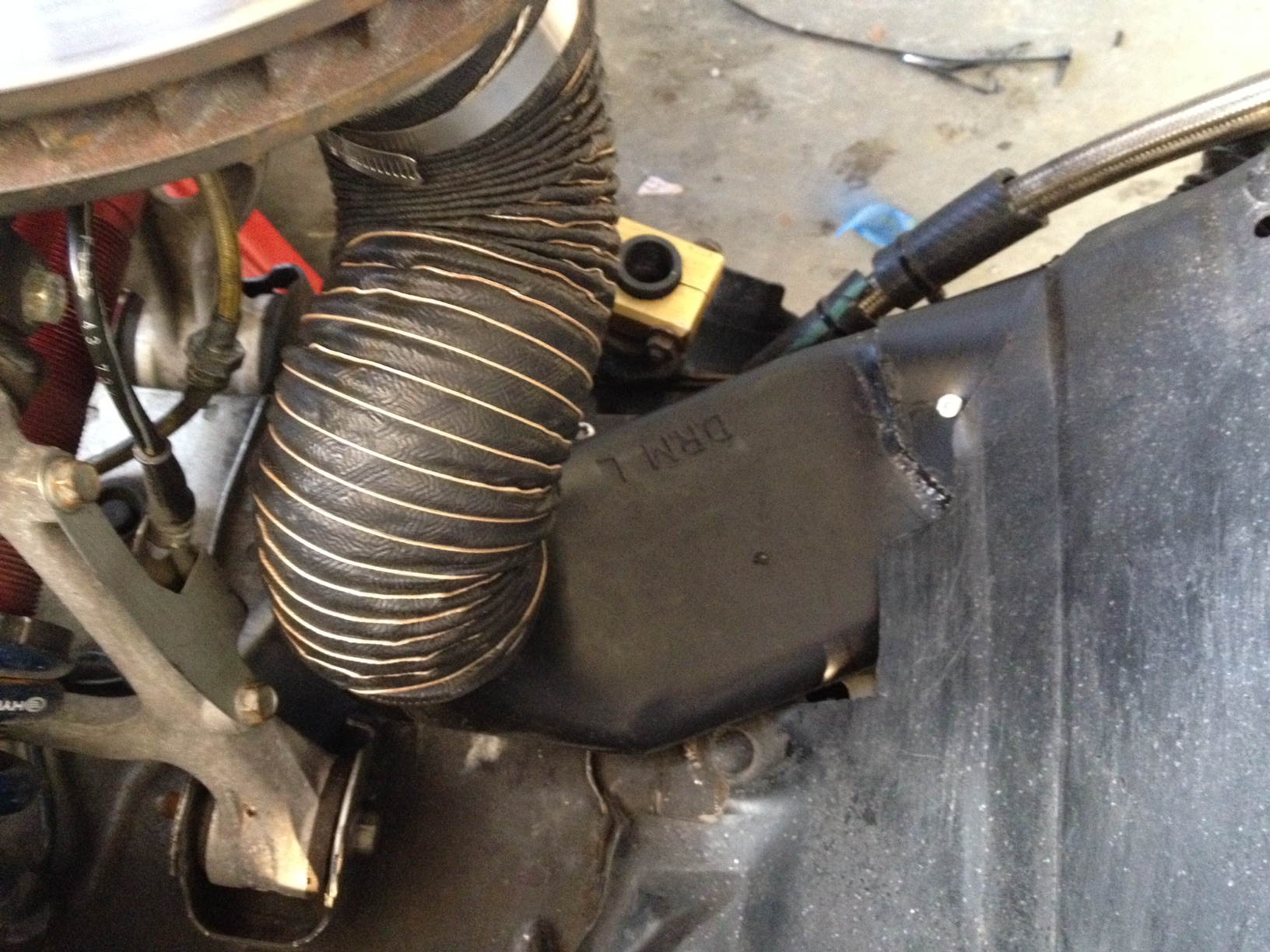
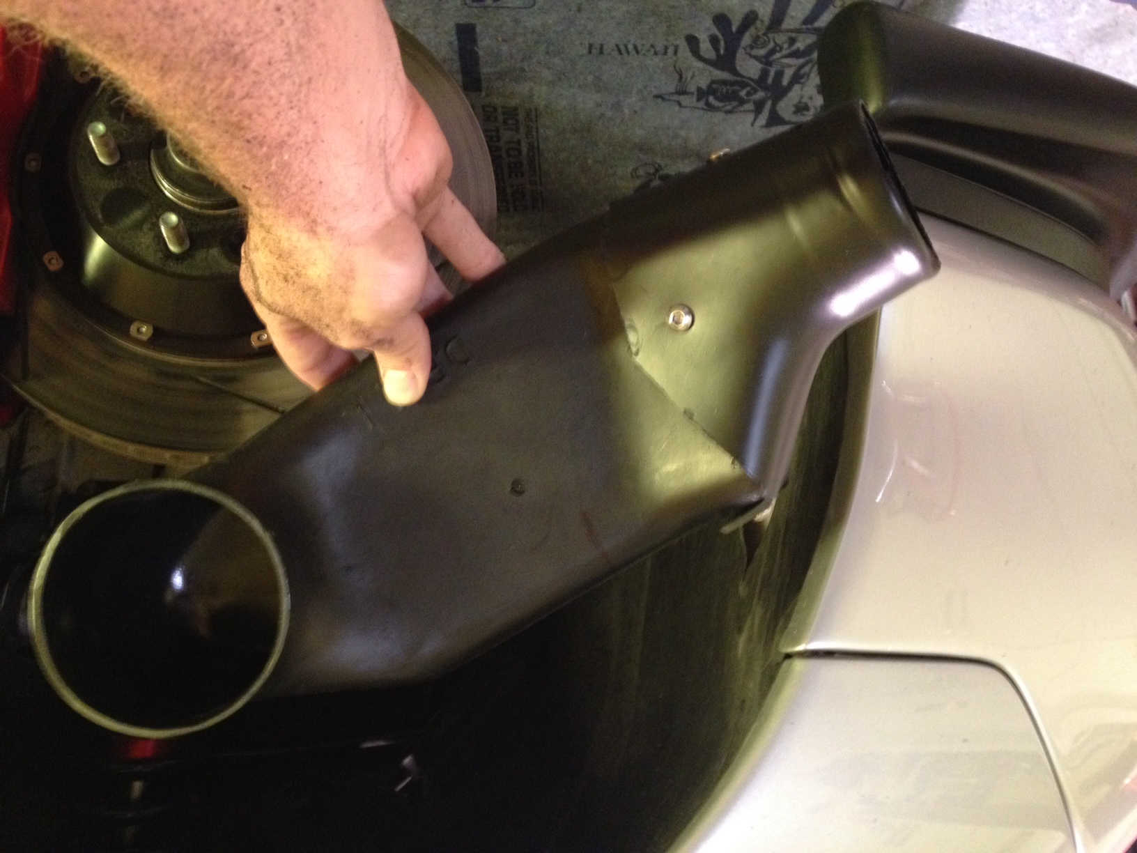
Sorry my pics come in upside down. I applaud the efforts, but as is noted, it's pretty easy to fab the spindle duct portion, I've had them made and also have a set of N-Tech's ones (not made anymore).
The trick is the house routing near where the tire would turn towards the frame... you just keep wearing through hoses. It seems corvettes have the same problem, hence the Doug Rippie Motorsports wide/flattened duct sections I used. Note, though, for our cars they really need to be like 3/4 scale... the inlets were 4.5", and the outlets are 3.5. I cut and grafted a smaller standard bumper duct to the front of them, so I could use a reasonably sized hose.
If I knew how to use CAD, and had access to 3D printing like you do, I'd buy a set of those Doug Rippie ducts, and set about miniaturizing and optimizing them for our cars. That flat section is about 6"x1".
Hey all, unfortunately life took over and this little design project fell to the back burner for quite some time... sorry for the lack of progress!
I ended up picking this back up recently, and I was able to run a version of the sheet metal/tube fabricated design on the spindle, along with a 3d printed bumper duct piece.
I used a thin wall 3" intercooler pipe with a rolled end and squashed it into an oval at the rotor side, so cross section area is maintained, and thus the flow is relatively undisturbed.
The brakes survived a 100F+ track day at Buttonwillow with greatly improved performance, but there is still some room for improvement.
My car is running a '93 front bumper with a '99 lip. Currently the 3" bumper duct is hooked up to the openings that normally serve the oil coolers, but I'm going to make a new one to mate to the lower lip opening instead.
I'm open to designing some additional bumper inlet ducts for other bumper designs, but would only be able to offer the '93 and '99 OEM bumper options first.
Are there other bumper designs people would like a duct designed for?
Also, what size wheels and tires are people running? I had no issues routing a 3" duct through next to the sway bar bracket, but if people are running huge wheels this might not work.
I'm working on updating the part geometries and getting a version made for the lower lip intake rather than the inlet for the oil coolers, as well as another novel concept that would be bumper design independent.
Right now the only 3d printed portion I am running is the adapter to the bumper fascia. The backing plate at the rotor is metallic, but I'm working with someone now to see if we can get a carbon solution completed for this. Expect some results in the next few weeks - unfortunately this isn't my day job!
Do you anticipate any binding with the hoses at full lock? If so, a possibility for quick release of a hose section for street driving?
It would depend on your wheel and tire setup, as well as ride height, however the way I routed my ducts I do not have any clearance issues to the 3" duct even at full lock. Clearance only gets better with more bump.
I run 255 width tires on an 18x8.75" wheel with a offset 33 wheel up front, for reference.

 10-20-16, 12:28 AM